1. Introduction
Wild land fires pose significant challenges to both ecosystems and human safety, necessitating innovative approaches for effective management and mitigation. Unmanned aerial vehicles (UAVs), commonly known as drones, have emerged as invaluable tools in addressing various aspects of wildfire and prescribed fire science. As highlighted in the results published in the paper by Nathalie Guimarães et al. [
1], a range of payloads attached to UAVs can be effectively utilized in forest fire and post-fire monitoring scenarios. The use of UAVs in various contexts offers substantial benefits, including cost reduction, temporal and spatial flexibility, high-precision data acquisition for tasks such as data collection and mapping, rapid damage assessment, and the inherent advantage of avoiding human risk [
2]. For instance, LiDAR sensors can be utilized to map areas with higher biomass fuel concentration and to capture small changes in micro topography [
3], as well as for characterizing and modelling power lines and for monitoring surrounding vegetation. As reported by Hernández-López et al. in their study [
4], high-voltage power lines can represent a hazard, causing or increasing the intensity of forest fires. The most recent studies have tended to use LiDAR devices onboard, as they provide a higher density of points and particularly good performance for digitizing power lines and calculating vegetation heights and volumes to estimate fuel models. Additionally, RGB and thermal infrared (TIR) cameras can assist in the monitoring of hotspots [
5,
6,
7], the recognition of persons and animals [
8], or even enhancing the management of field teams [
9]. Forest restoration and recovery in post-fire scenarios is crucial for improving/studying recovery and measuring fire severity, allowing quicker intervention [
10,
11]. In this context, TIR sensors as sensing payloads have proven useful for real-time fire monitoring, while multispectral sensors have demonstrated potential in post-fire forest rehabilitation [
12].
In wildfire management, UAV architecture is tailored for rapid deployment, versatility, and robust data acquisition. Fixed-wing UAVs excel in long endurance and broad coverage, making them ideal for initial wildfire detection and continuous monitoring [
13]. Multirotor UAVs offer maneuverability and precision, essential for navigating complex terrains and assessing fire-affected areas in detail [
14]. Integrating multi-UAV systems enables cooperative surveillance, ensuring quality of service and efficient resource allocation [
14]. These UAVs are typically part of a larger network including ground stations that manage communications, control, and critical data processing for timely and effective wildfire response.
Recognizing the diverse applications of UAVs, there arises a need for a multipurpose drone. Such a drone should be capable of hosting all these diverse payloads, regardless of weight, and possess the adaptability to change its configuration and payload swiftly. The ability to make rapid adjustments is crucial in circumstances where time is of the essence, optimizing the drone’s efficiency and effectiveness in addressing the complex challenges posed by wildfires and their aftermath.
To meet these multifaceted demands, the field of UAV development is rapidly advancing in its design approaches, with application of computer-aided techniques (CAx) leading the innovation charge. The integration of CAx techniques and innovative design approaches plays a pivotal role. Qin, Z. et al. [
15] demonstrated this through their conceptualization of a multi-rotor UAV with variable paddle pitch, leveraging CAx tools for optimization prior to prototyping. Skarka, W. et al. [
16] furthered this notion by employing generative modelling to automate design variations, enhancing efficiency and adaptability in the design process. Complementing these studies, Łukaszewicz, A., Szafran, K., and Józwik, J. [
17] underscored the significance of CAx systems in reducing development times and fostering modern engineering education, particularly emphasizing the impact of parametric and 3D hybrid modelling on UAV innovation. Collectively, these works mark the transformative potential of CAx methodologies in the UAV industry, from conceptual design to final production.
In response to the evolving demands across various domains, including those posed by wildfires, ongoing efforts have increasingly shifted towards the study and development of reconfigurable systems. The list encompasses field-programmable gate arrays [
18], reconfigurable machine tools [
19], morphing-wing UAVs [
20], and reconfigurable modular space systems [
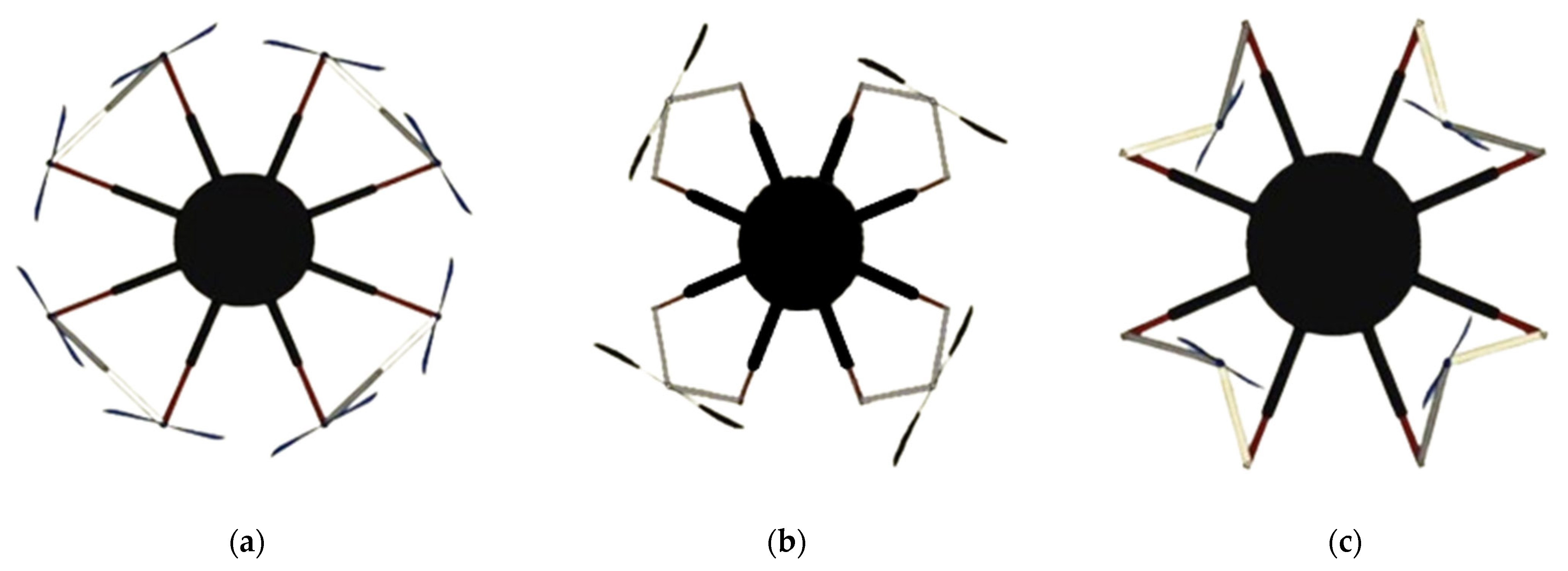
21]. With the escalating global use of UAVs, the concept of reconfigurable UAVs has caught the attention. Currently available on the market are various types of multirotor UAVs that vary in configuration, mission type, dimensions, and materials utilized. Nevertheless, a majority of UAVs in today’s market, characterized by a fixed payload capacity range and a set number of rotor arms, are highly specialized for specific task execution. As a result, the challenge of specialized tasks arises; numerous models tailored for different purposes must be developed and mass-produced to create a diverse range of UAVs. As a consequence of this, companies are actively investigating novel concepts for offline reconfiguration of UAVs, aiming to enhance their adaptability and performance in diverse operational scenarios.
One of the most explored ideas involves connecting multiple rotors to facilitate the transportation of heavy loads, such as the drones produced by the Latvian firm Aerones. An interesting patent is referenced in [
22], where the drone is composed of a central perforated circular frame without arms, with motors and propellers positioned in various holes to achieve various configurations. The proposed drone, however, is not modular and lacks arms. Patent [
23] introduces a circular plate connected to an external ring via three sticks, allowing the positioning of rotors in a variable number but only in a predetermined order. Another patent [
24] proposes a drone with three arms, each equipped with two rotors. This structure permits the inclination of the plane where the three arms are situated but exhibits limited flexibility. A comparable design is presented in patent [
25], featuring a quadrotor structure that can be positioned at different angles. However, this structure also exhibits restricted flexibility. All the aforementioned technical solutions lack modular capabilities, and, in particular, they do not enable flexible use of the drone. More specifically, the described technical solutions share the major drawback of not allowing configurations beyond those initially provided.
Aside from the previously mentioned patents, significant advancements in drone technology involve the capability to change arms. Yuying Qian et al. [
26], proposed a drone design concept capable of switching between a quadcopter and a hexacopter. While that design allows users to transform the UAV without adjusting the positions of the four rotor arms, it is restricted to configurations with only four or six motors. Additionally, the UAV’s payload capacity is limited to 600 g, limiting its potential mission capabilities. To achieve adaptability, the UAV incorporates two distinct flight controllers for each configuration, resulting in the absence of automation during the transition between configurations. Another noteworthy approach is the drone proposed by S. Brischetto et al. (2016) [
27,
28]. This modular drone features a universal platform that supports 12 different configurations. However, changing the UAV’s configuration requires disassembling all the parts, and the user must then reassemble them. This poses a prohibitive factor in cases where time is precious, such as in firefighting or fire prevention scenarios, where quick changes in both the drone’s configuration and payload may be necessary for various missions. Another limiting factor is the maximum take-off weight (MTOW), including the UAV’s construction, which is set at 2 kg. This limitation implies that the UAV may struggle to accommodate the variable payloads essential for missions in wildfires and prescribed fire sciences. In contrast to the previously mentioned drone, the UAV outlined in the paper by D. Kotarski et al. [
29] exhibits the capacity to transport payloads ranging from 5 to 50 kg, underscoring its adaptability to diverse mission requirements. Despite the UAV’s suggested reconfigurability into three distinct configurations—quadcopter, hexacopter, and octocopter—the authors provide no details on the procedural aspects involved in altering its configuration or the associated ease and time commitments. Moreover, it remains undisclosed whether the uploading of the correct firmware for each configuration into the flight controller is performed automatically or not, representing a potentially time-consuming task demanding technical proficiency. Further contributing to this field, Moral, K. et al. [
30] designed a modular multi-drone system with vertical assembly capability. The proposed design offers increased payload capacity due to modular stacking ability and operational flexibility, with the drone capable of functioning both individually and collectively. While the novel control method is beneficial, controlling a vertically assembled structure presents more complexity than a single UAV. Additionally, potential mechanical failures in the docking mechanism and regulatory challenges in densely populated areas also pose concerns. The Drone Reconfigurable Architecture (DRA) by da Silva Ferreira, M.A. et al. [
31] offers enhanced versatility and customization for a variety of UAV applications, allowing end users to attach multiple modules for the desired configuration and thrust weight. However, the authors do not specify the maximum payload weight achievable nor detail the payload attachment procedures. Moreover, the absence of landing gear compromises the drone’s ability to take off from varied terrains, which is essential for a multipurpose UAV. To conclude, these solutions do not have total modularity for all their elements (i.e., structural, avionic, and electrical parts) and they require some basic electronic and mechanical knowledge from the end users to be able to properly assemble the available elements. Moreover, none of the prior technical solutions solve the problem of providing a multifunction and multipurpose drone able to carry a generic payload that can vary in weight while also being deployable with simple and easy plug-and-play procedures.
The concept presented in this paper goes beyond previous works on modular architectures. This paper adopts an offline modular strategy to introduce a “never-seen-before” reconfigurable architecture designed for multirotor drones. This innovative approach allows rapid assembly and configuration adjustments tailored to specific mission requirements, ensuring that the UAV is mission-ready in a short timeframe. Moreover, this architecture allows for the replacement or upgrade of individual parts of the UAV. In addition to offering various configurations, the innovation presented also extends to UAV control. The drone’s specific configuration is identified automatically, and the UAV controller adapts accordingly. Delivery of the appropriate firmware to the controller is executed automatically through custom and pre-configured options and auto-install methods.
4. Electronics Design
4.1. Motors [P80 III Pin KV100]
Embarking into the realm of UAVs demands an in-depth analysis of components to ensure optimal performance, and among the critical considerations is the choice between brushless and brushed motors. The advantages of brushless motors, ranging from a remarkable power-to-weight ratio to high-speed capabilities, electronic precision, and low maintenance requirements [
36], make them particularly well suited for this application. In the complex process of motor selection, factors such as thrust, efficiency, and propeller size play pivotal roles, setting the stage for an informed decision. In many cases, tables of experimental results (
Table 1) facilitated the selection of a brushless motor. Each row of the table indicates various elements, such as the current and the efficiency, which correspond to the thrust force. For example, when the exerted force is 4114 g for the T-MOTOR G30*10.5CF propeller (T-Motor, Nanchang, China), the amperage draw is 7.99 A, while the efficiency is 10.77 G/W.
Before proceeding to the motor selection process, it is essential to conduct an initial calculation of the total weight of the UAV, including peripheral equipment. This step is crucial for computing the necessary thrust that each actuator must provide during hovering. As mentioned in the preceding section, PULSAR has three distinct configurations, each with different technical specifications. For this prototype, the maximum take-off weight (MTOW) of the drone was capped at 25 kg, accounting for all peripheral equipment, to adhere to the A3 open category regulations outlined by EASA for drones.
To select the most appropriate motor, all three configurations were considered, ensuring that the take-off weight remained at 25 kg. Each motor must provide a maximum thrust of at least twice the hovering thrust force per motor to ensure the UAV’s capability for take-off and altitude increase. Additionally, efficiency is crucial, with higher efficiency values indicating greater thrust per Watt, thereby minimizing power consumption. Considering the rapid evolution of technology, the selection process also prioritizes flexibility for end-users. This includes the ability to attach different and weightier payloads in the near future while maintaining the requirement for each motor’s maximum thrust to be at least twice the hovering thrust.
In the context of PULSAR prototype, the T-MOTOR P80 III PIN KV100 stood out as the chosen brushless motor, leveraging the robust capabilities of the P-Series motors originally designed for agricultural applications. These motors offer a blend of powerful thrust and high performance, backed by features like dustproofing, waterproofing, anti-corrosion properties, and resistance to high temperatures.
As we delve into propeller choices, the drone further demonstrated its adaptability through accommodating various propellers tailored to different configurations, allowing users to achieve diverse technical specifications. The selection required careful consideration of various factors including lift requirements, weight considerations, space constraints, and control demands. Through examining the potential advantages of using different propeller sizes for each configuration, we tailored our choices to best suit the specific needs of each drone design, ensuring optimal performance and functionality. In the propeller propulsion systems, the numerical notation adjacent to a propeller’s designation denotes crucial specifications related to its dimensions and performance characteristics. Comprising two sets of digits, these numbers represent the diameter and pitch of the propeller blades. The first set signifies the diameter of the propeller in inches, while the subsequent set, often following a letter code or ‘x’, indicates the pitch, also measured in inches.
Critically evaluating these factors, it was found that the octocopter configuration benefited from smaller T-MOTOR G30*10.5CF propellers, optimizing agility and manoeuvrability and at the same time maintaining a reduced footprint without compromising lift capacity. Conversely, the quadcopter configuration excelled with the T-MOTOR G32*11CF propellers, maximizing lift for heavy payloads and enhancing the ability to withstand wind forces. Similarly, the quadcopter co-axial configuration also benefited from the larger propellers, leveraging their enhanced control and efficiency to navigate in turbulent conditions, which is particularly advantageous for applications requiring smooth aerial footage. This strategic combination enhances overall efficiency and adaptability while also aligning seamlessly with the UAV’s objectives. The technical specifications of the motors, along with the relevant propellers, can be found in
Table 1.
4.2. Electronic Speed Controller (ESC) [Flame 80A 12S V2.0]
Most drones utilizing PX4 open-source flight control software employ brushless motors controlled via the flight controller through electronic speed controllers (ESCs). An ESC is a module that converts a signal from the flight controller into the appropriate power level for the motor, allowing for modulation of its angular velocity. PX4 supports various types of ESCs, including PWM-based ESCs as well as those utilizing the OneShot or the DShot protocols.
In this project, we have chosen the T-MOTOR FLAME 80A 12S to serve as the interface between the motors and the flight controller. When selecting ESCs for this application, their compatibility with the chosen motors was taken into account, as well as their maximum current output to ensure it met the motor’s requirements.
4.3. Flight Controller [Pixhawk 5X]
The selection of the flight controller was based on the physical constraints of the vehicle, as well as the activities that need to be performed. There are many autopilot hardware boards that can be used to run the PX4 flight stack, such as Qualcomm Snapdragon Flight, Raspberry Pi 2/3 Navio2, and BeagleBone Blue. In addition to these solutions, there is the Pixhawk, which constitutes an independent open-hardware project that aims to provide the standard for readily available, high-quality, low-cost autopilot hardware designs; most importantly, it supports PX4. The Pixhawk Series is a prevalent set of flight controller boards that is preferred by the academic, hobby, and developer communities and provides various versions targeted towards many use cases and market segments.
For the development of this UAV, from among the different boards that are included in the Pixhawk Series, the Pixhawk 5X, version 1.14, was used as a flight controller. Pixhawk 5X is a top-tier flight controller with triple redundancy, advanced sensors, and pre-installed PX4 Autopilot. Powered by an STMicroelectronics STM32F7 microcontroller, it offers exceptional flexibility and reliability for various autonomous vehicles, serving both academic and commercial purposes. The FMUv5X open standard [
38] includes high-performance IMUs for improved stabilization and seamlessly switches to redundant sensors in case of failure. Independent power control for each sensor set, noise reduction through vibration isolation, and versatile connectivity via SPI5 and ethernet ensure precise readings and enhanced overall flight performance. Compatible with PX4 Autopilot, the Pixhawk 5X is ideal for corporate research, startups, academia, and commercial applications.
4.4. Air-Frame Selection and Validation Board/Circuit
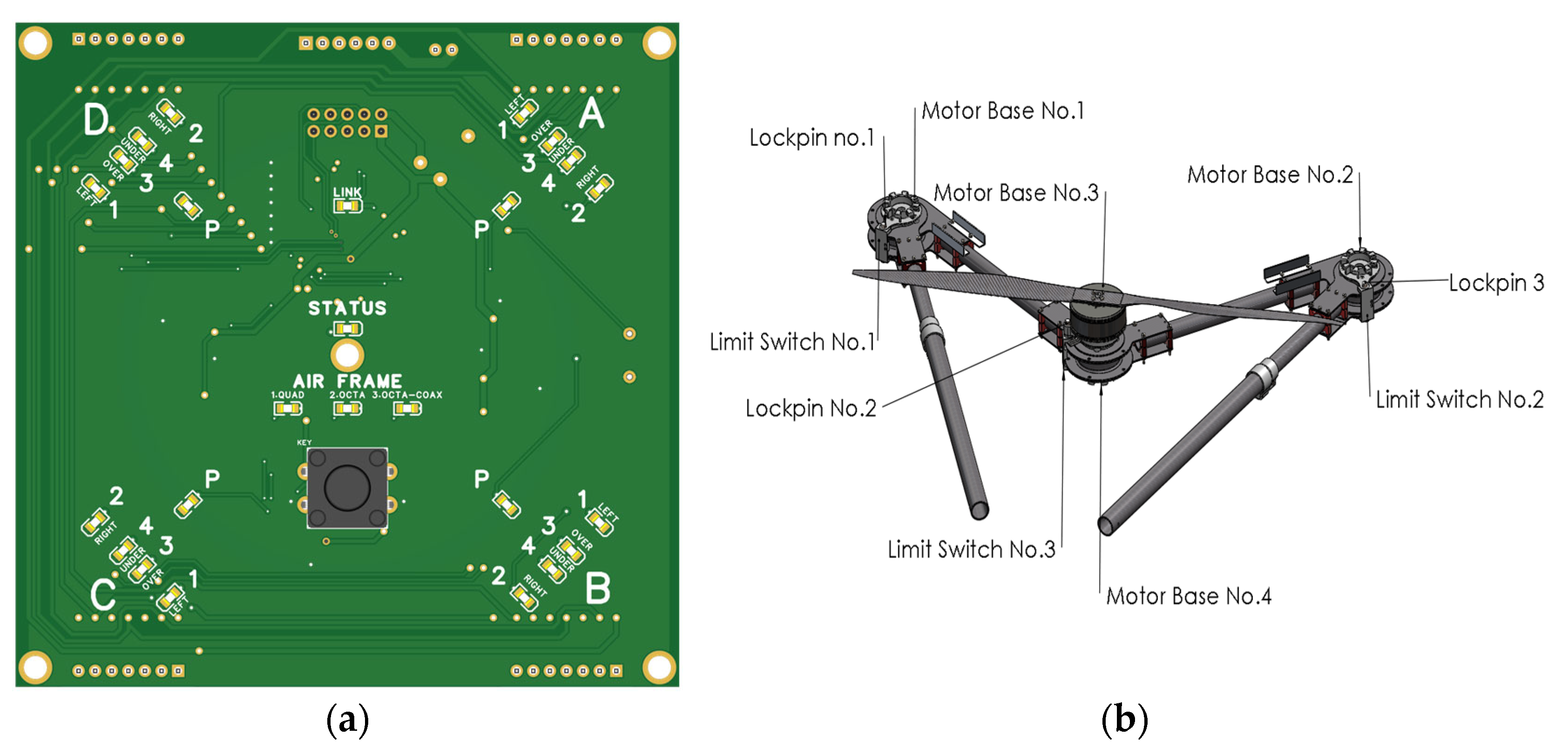
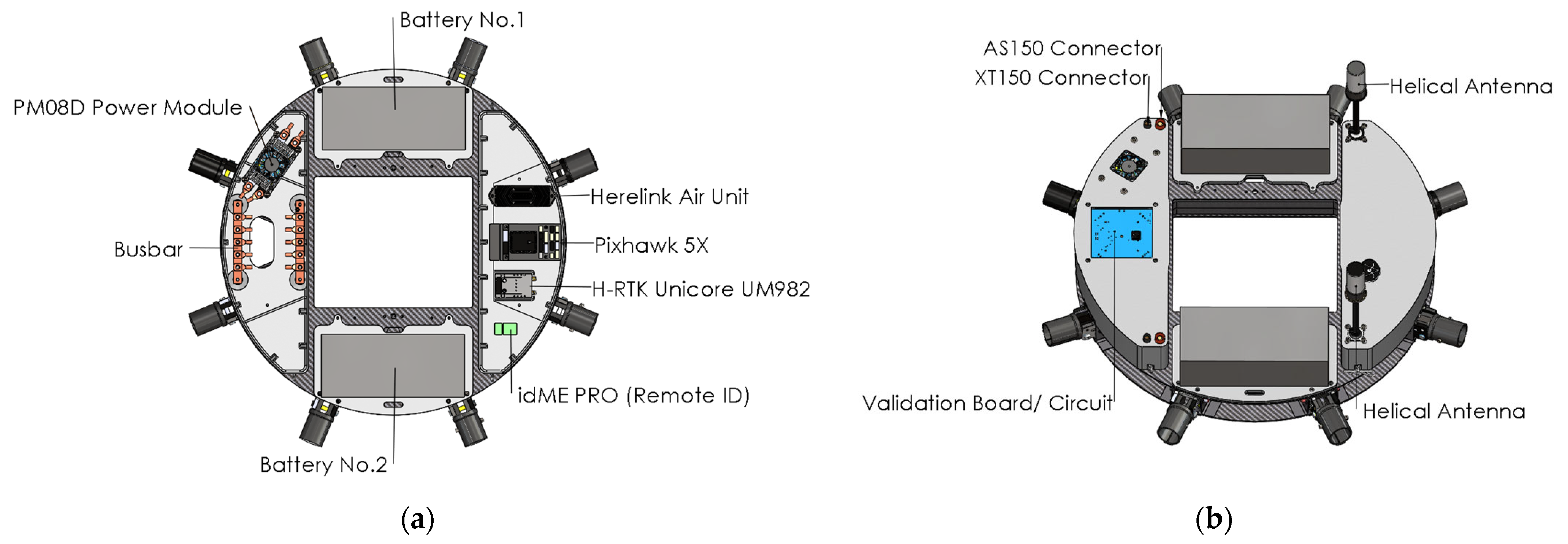
The frame recognition board has been built around an ARM Cortex M0+ microcontroller (STM32G0) and features 20 red LEDs divided into four groups of 5 LEDs (A, B, C, D), with each group representing the four pairs of arms, a green status LED, three blue LEDs for airframe indication, a preset selection button, and a link LED (
Figure 3). Users can select a frame by pressing the button, cycling through presets: 1 for QUAD (quadcopter), 2 for OCTO (octocopter), and 3 for QUAD–COAXIAL (co-axial quadcopter).
After selecting a frame, the board indicates (using red LEDs) all the required connection positions for the chosen frame for 1 s. Then, it constantly checks for the actual connections required, indicating (in red) all connections that need to be altered.
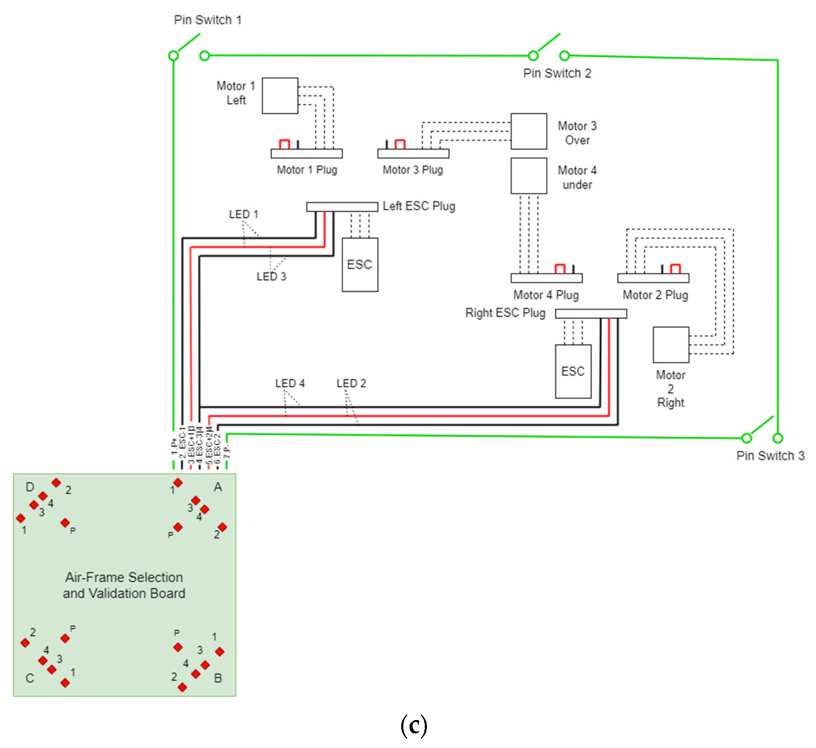
The red LEDs of each group correspond to the four motor positions and to the locking pins of the joints. A red LED ON indicates that there is a faulty condition (a connection that should be made is not present or a connection that should not be made is present), relative to the selected air frame. For example, if frame 3 (QUAD-COAXIAL) is selected, the system expects to see Motors 3 and 4 of each group connected. If any of these motors are not connected to the corresponding ESC, its LED will be ON, indicating that the motor must be connected. Also, if any of motors 1 and 2 in any group are connected, the corresponding LED will also be ON, indicating that this motor needs to be removed.
Additionally, there are 12 locking pins, 3 in each pair of arms, that ensure that the joints of the arms are immobilized. Each of the four LEDs marked with the letter P checks the three locking pins. The system requires all three pins to be in place for the LED to turn OFF. These locking pins close a circuit through a limit switch attached to each joint of the UAV.
If all connections are correct, all red LEDs turn OFF and the board communicates with the flight controller. The board then loads the selected frameset to the flight controller and restarts the flight controller system. The status LED flashes green. The board waits for the flight controller to initialize with the new airframe, and the status LED becomes a steady green. The system is then ready for flight.
In case of a power off–on cycle, the frame recognition board loads the last preset.
4.5. GNSS Module [Holybro H-RTK Unicore UM982 (Dual Antenna)]
The usage of UAVs in the current work necessitates high-precision geolocation to ensure the reliability of any information related to objects detected through corresponding algorithms and transmitted to end-users. The Holybro UM982 Dual Antenna RTK GPS (Holybro, Hong Kong, China) meets this need by providing high-precision positioning information, even in challenging environments where signal obstructions or multipath interference may occur. Capable of generating non-magnetometer moving baseline yaw determinations for autopilots with one single GPS module, the UM982 offers compass-less YAW information, preventing magnetic interference and environmental sources from causing incorrect yaw reports. Additionally, it includes features such as a magnetometer, LED, and safety switch button. As an RTK-corrected vehicle GPS, it serves as a base station GPS for sending RTCM data to a ground control station, providing an RTK source for the vehicle via telemetry. Leveraging carrier phase measurements from multiple satellite constellations including GPS (L1C/A/L2C(P)/L5), GLONASS (L1/L2), Galileo (E1/E5a/E5b), QZSS (L1/L2/L5), and Beidou (B1I/B2I/B3I), the UM982 calculates precise position, velocity, and orientation information in real time, delivering centimeter-level accuracy ideal for applications such as aerial surveying, precision agriculture, and infrastructure inspection.
4.6. Remote Identification Device [Aerobits—idME PRO]
From 1 January 2024, all drones operating in specific categories, as well as those with class marks operating in the open category, will be required to have an active and up-to-date remote identification system [
39]. This involves equipping drones with technologies that enable authorities and members of the public to remotely identify drones both in the air and on the ground, using a smartphone app. This may entail transmitting identification information such as the drone’s serial number, operator registration number, remote pilot position, or, if unavailable, the take-off point and the drone’s location. Such technology is crucial for enabling the tracking and monitoring of drones, enhancing airspace security, and facilitating the integration of drones into existing airspace systems.
For the PULSAR prototype, we have selected the iDME PRO remote identification device from Aerobits (Aerobits, Szczecin, Poland), which is listed in the EU Declaration of Conformity. The idME PRO is specifically designed to meet the remote drone identification and localization requirements outlined in ASTM/ASD-STAN standards [
40,
41]. Leveraging BLE broadcast technology, this device offers surveillance and drone operator identification capabilities compatible with any modern mobile device, such as a smartphone or tablet.
4.7. Battery [Tattu 22.8V 25C 6S 23,000 mAh Lipo HV Battery (Tattu, Shezhen, China)]
Lithium polymer (LiPo) batteries are rechargeable batteries that use lithium-ion technology and a semisolid (gel) polymer electrolyte instead of an electrolyte in a liquid form. They provide very high specific energy (per their unit of mass) and therefore are widely used in mobile phones, multicopters, and other mobile equipment.
There are three important parameters that should be taken into account before battery selection: cell configuration, C-rating, and battery capacity. First of all, the number of cells defines the voltage of the battery. Each cell has a nominal voltage of 3.7 V, so a 6S battery thus provides 6 × 3.7 V = 22.2 V. C-rating is an indicator of the continuous discharge rate of a LiPo. It allows users to easily calculate the maximum constant current that can be drawn from the LiPo pack safely without harming the battery. For instance, a 6 s 23,000 mAh 25C LiPo pack has a maximum amperage draw of 25,000 mAh/1000 × 25C = 625A. Lastly, the capacity determines how long a battery can run before it needs recharging. A larger capacity pack may give longer flight times but being heavier, it will adversely affect performance.
The following Equation (2) determines the flight time, knowing the current drawn from the LiPo battery of the multicopter as well as the specifications of the battery, where the battery discharge indicates the effective capacity of the battery:
Using a discharge of 0.8, the selected battery provides almost ~25 min of flight time. Note that, for the proposed UAV, two identical batteries are used in series configuration; hence, the total battery voltage is 45.6 V while the total battery capacity remains 23,000 mAh.
It is important to note that the UAV has been designed with a relatively spacious interior to accommodate various pairs of batteries. Each pair of batteries can serve different purposes or needs, providing flexibility in the UAV’s power supply and mission requirements.
4.8. RC Controller—Telemetry Module [Herelink HD Video Transmission System V2]
Before configuring the companion computer, in which smart AI algorithms enable the vehicle to autonomously perform various tasks such as image and video processing, object detection, and monitoring, it was essential to conduct numerous tests in manual mode. These tests served to validate the sufficiency of the equipment and the efficiency of the controller. Furthermore, even during autonomous flight, it is mandatory to be able to control the UAV manually in case of an emergency.
To operate the UAV manually, a radio control (RC) system is required, allowing the vehicle to be controlled from a handheld transmitter. The RC system consists of a ground-based remote-control unit used by the operator to command the vehicle, and a radio module mounted on the vehicle. This radio module serves as a receiver connected to the flight controller unit, which interprets the operator’s commands.
Herelink (Cube Pilot, Breakwater, Australia) emerges as an integrated solution for seamless compatibility with leading autopilot systems such as the Cube Autopilot, Ardupilot, or PX4. Combining the functionalities of a remote controller, ground station, and wireless digital transmission system, Herelink streamlines essential drone operations into a cohesive unit. Operators benefit from a comprehensive suite of capabilities, including RC control, high-definition video transmission, and telemetry data dissemination, reliably communicated over impressive distances of up to 12 km between the ground station and air unit. The Herelink remote controller features customized Solex TX and QGC applications, tailored to optimize user experience and operational efficiency. Both the air unit and ground station feature an integrated eight-core system-on-chip (SOC), laying a robust foundation for the development and implementation of custom applications. Its reliability and performance make it an ideal choice for demanding environments where precise control, data integrity, and uninterrupted communication are paramount.
4.9. Connectivity Block Diagram
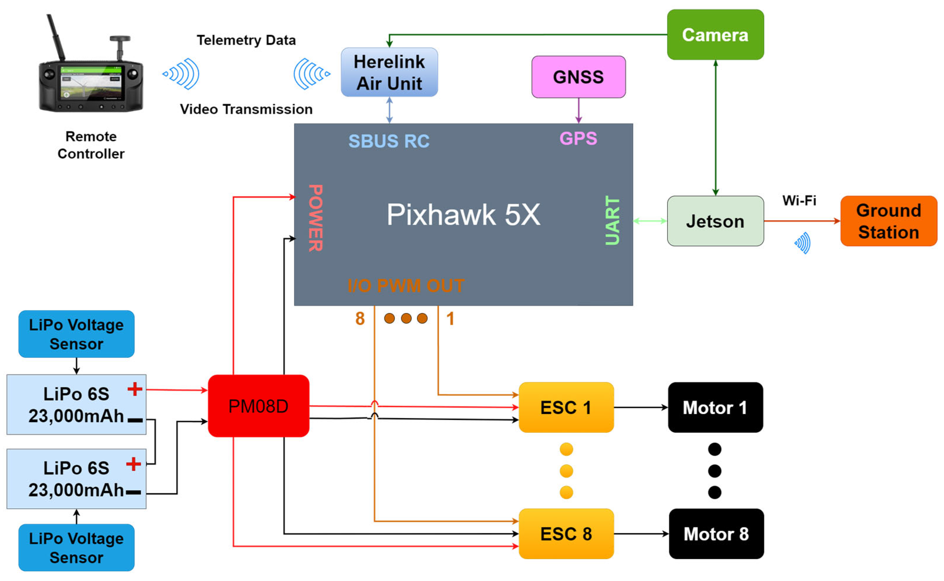
In this section, the authors present their vision of the proposed UAV connectivity architecture. The development of this architecture takes into account the design requirements and needs that must be considered when designing the UAV (
Figure 4).
6. PULSAR Applications in Forest and Wildfire Management
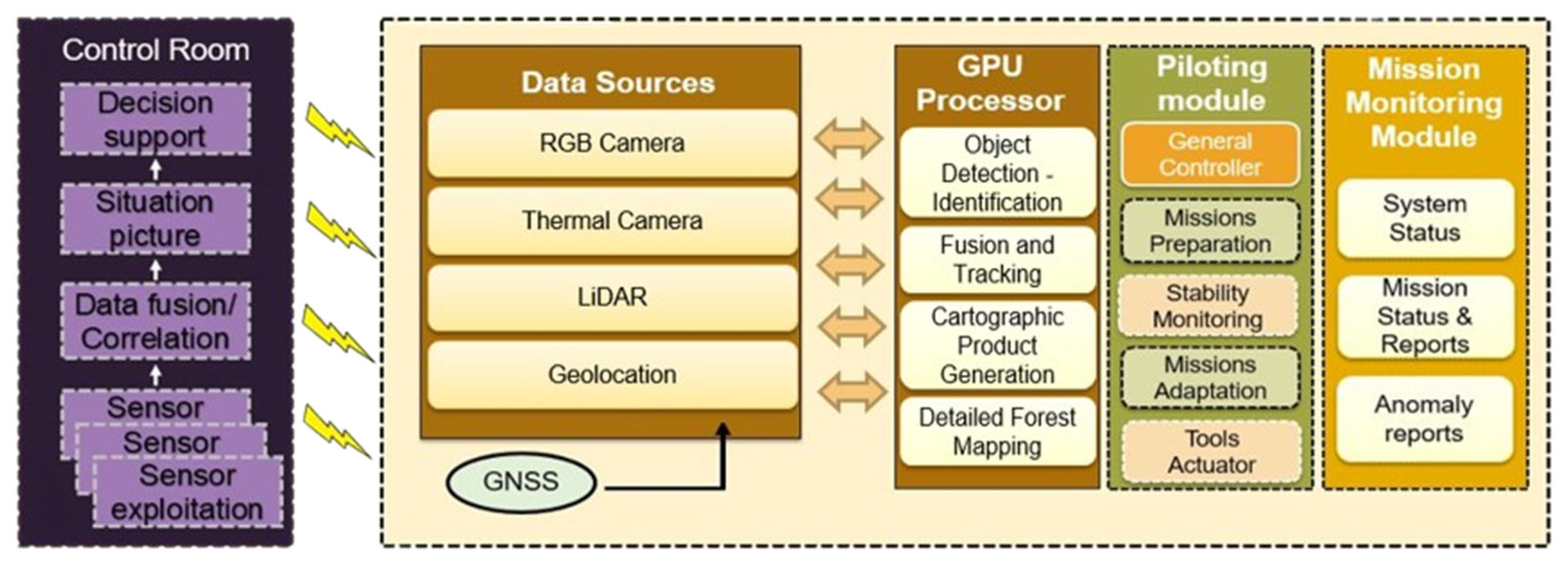
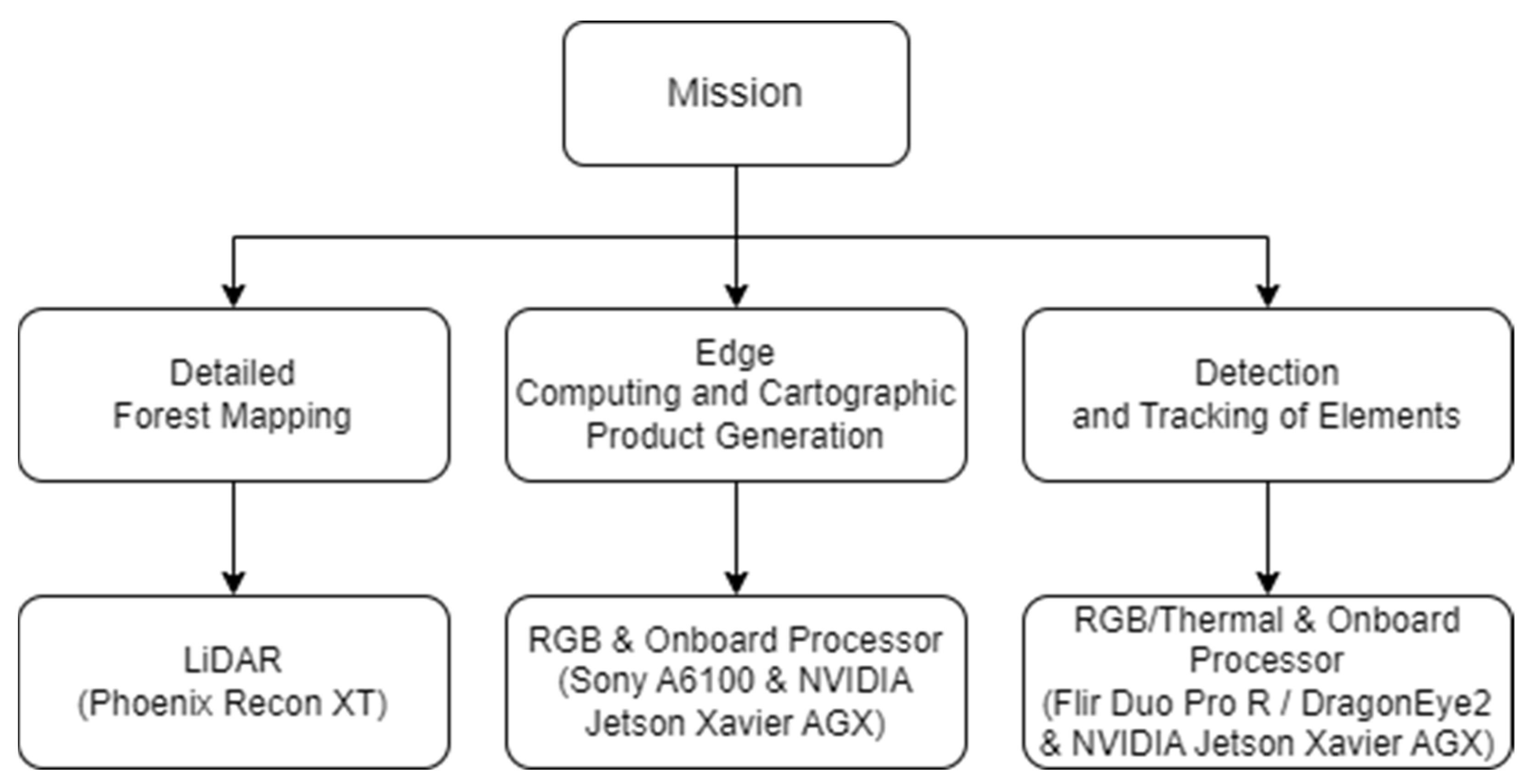
The use of UAVs for research and operations on wildland fires has been rapidly accelerated by advancements in aircraft systems, sensor technologies, telemetry, and computing capabilities. Drones have evolved beyond mere observational tools, transforming into versatile instruments with the ability to revolutionize the landscape of wildfire research and operational strategies. Beyond the various configurations of the UAV, this article also explores its ability to accommodate a range of payloads, thereby addressing crucial aspects of wildfire and prescribed fire science. In particular, the drone’s capabilities extend across three vital categories: (i) detailed forest mapping, (ii) edge computing and the generation of cartographic products on the fly, as well as (iii) detection and tracking of elements such as people, animals, and vehicles.
6.1. Detailed Forest Mapping
Detailed forest mapping using UAVs is a crucial aspect of wildfire and prescribed fire sciences. This paper focuses on adapting a LiDAR sensor to the proposed UAV, an advanced tool capable of capturing high-resolution imagery that enables the precise mapping of vegetation types, fuel loads, and topography. As highlighted in [
42], wildfire prevention efforts should concentrate on modifying forest fuels. At the landscape level, wildfires are ignited and spread through a complex interaction between weather, topography, and fuels. Fuel characteristics, such as the vertical and horizontal structure of vegetation, stand composition, and the properties of forest species, significantly influence the rate and intensity of fire spread. Alterations in fuel patterns lead to changes in fire behaviour. For prescribed burns, the information collected assists in planning controlled fires to ensure they align with ecosystem management goals. In practical scenarios, the proposed UAV equipped with a LiDAR sensor can be deployed to scan densely forested areas prone to fire during dry seasons. Analyzing these data aids in identifying strategic sites for fuel reduction treatments, such as thinning or controlled burns, substantially mitigating the risk of catastrophic forest fires. This enhances landscape understanding, enabling more accurate wildfire risk assessments and contributing to the development of strategic fire management plans [
43].
6.2. Edge Computing and Cartographic Product Generation on the Fly
Edge computing plays a crucial role in enhancing the agility of wildfire and prescribed fire responses [
44]. By processing data locally on the UAV, latency is reduced, facilitating the generation of real-time cartographic products. Drones equipped with both edge computing capabilities and RGB sensors can analyze flight data and generate dynamic maps on the fly. Among the various cartographic products that can be produced, one particularly valuable application is the generation of vegetation density and type maps. Leveraging the high resolution of RGB imagery and the processing power of the on-board processor, the PULSAR prototype can perform near real-time analysis to identify different types of vegetation and assess their density within the fire-affected area, providing firefighters with essential insights for making proactive decisions. For instance, they can identify areas with high vegetation density that are at greater risk of intense fire spread and prioritize suppression efforts accordingly. Additionally, the real-time mapping and analysis capabilities enable firefighters to adapt their strategies dynamically as the situation evolves, improving the overall effectiveness of wildfire response efforts and minimizing damage to the environment and surrounding communities.
6.3. Detection and Tracking of Elements
UAVs equipped with advanced detection technologies, such as thermal cameras and computer vision systems, are at the forefront of wildfire management and prescribed fire operations. The proposed UAV is able to adopt these technologies, which are adept at detecting and tracking critical elements including people, animals, vehicles, and hotspots. Thermal cameras play a key role in identifying heat sources that may signal an impending wildfire and in monitoring the progression of controlled burns, while computer vision algorithms enable the identification and tracking of specific elements, enhancing situational awareness [
45]. This is particularly beneficial for safeguarding personnel during firefighting efforts and for observing wildlife to minimize environmental impacts. The integration of these detection technologies into the proposed UAV bolsters the overall effectiveness of surveillance and response strategies in fire science, providing a vital tool for use in the preservation of natural landscapes and wildlife habitats.
6.4. Payload Categorization and Integration
The primary objective of this paper is the development of a singular, versatile UAV with the capacity to execute a wide array of missions in wildfires and prescribed sciences, thereby eliminating the necessity for multiple drones designed for specific tasks. To accomplish this objective, the UAV must be able to integrate all the required payloads according to the missions that the drone will execute. A list of all the required sensors that are needed and have been selected for each mission is available in
Figure 14.
In this regard, the proposed strategy entails the creation of specialized casings for each payload, which can be effortlessly attached to the UAV. These casings will be fashioned using carbon materials, serving a dual role: safeguarding the payload sensors and streamlining the attachment process for end-users. This will be achieved by incorporating quick-pairing fasteners.
The attachment process involves a simple plug-and-play procedure, wherein the users need only to position the casing in the dedicated space on the drone. Subsequently, they can secure the payloads along with their respective casings on the UAV by twisting the quick-pairing fasteners. This method ensures safety during flight, with the added benefit of an extremely short assembly and disassembly time, typically under a minute. It is worth noting that both the dedicated space on the UAV and the payload casings have been carefully designed to accommodate sensors of varying dimensions, underscoring the adaptability and versatility of the proposed drone.
Below, considering all the points mentioned above, is a comprehensive overview of each payload, along with its uniquely designed case tailored exclusively to fit the drone, emphasizing the system’s adaptability and flexibility.
6.4.1. LiDAR Sensor [Phoenix RECON XT]
The LiDAR RECON-XT (Phoenix LiDAR, Austin, TX, USA) laser mapping system represents an exceptional fusion of performance, flexibility, and weight optimization in the field of LiDAR technology. Designed primarily for UAVs, the RECON-XT stands out as the leader within its weight class. Notably, it offers a distinctive advantage with its exceptional versatility in mounting options.
Moreover, the RECON-XT showcases its impressive capabilities through its multi-target capacity, significantly expanding its operational scope. This advanced LiDAR sensor enables the collection of highly detailed and accurate 3D point cloud data, making it the preferred choice for professionals seeking efficient and flexible solutions for mapping and surveying projects [
46].
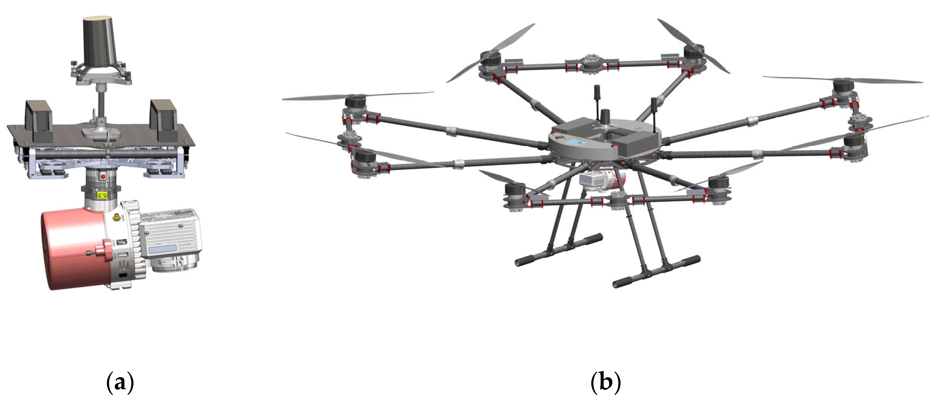
The technical specifications of the selected sensor (
Table 2) are presented next, followed by the custom payload case that will be developed and the configuration that will be housing it (
Figure 15).
6.4.2. RGB Sensor [Sony A6100]
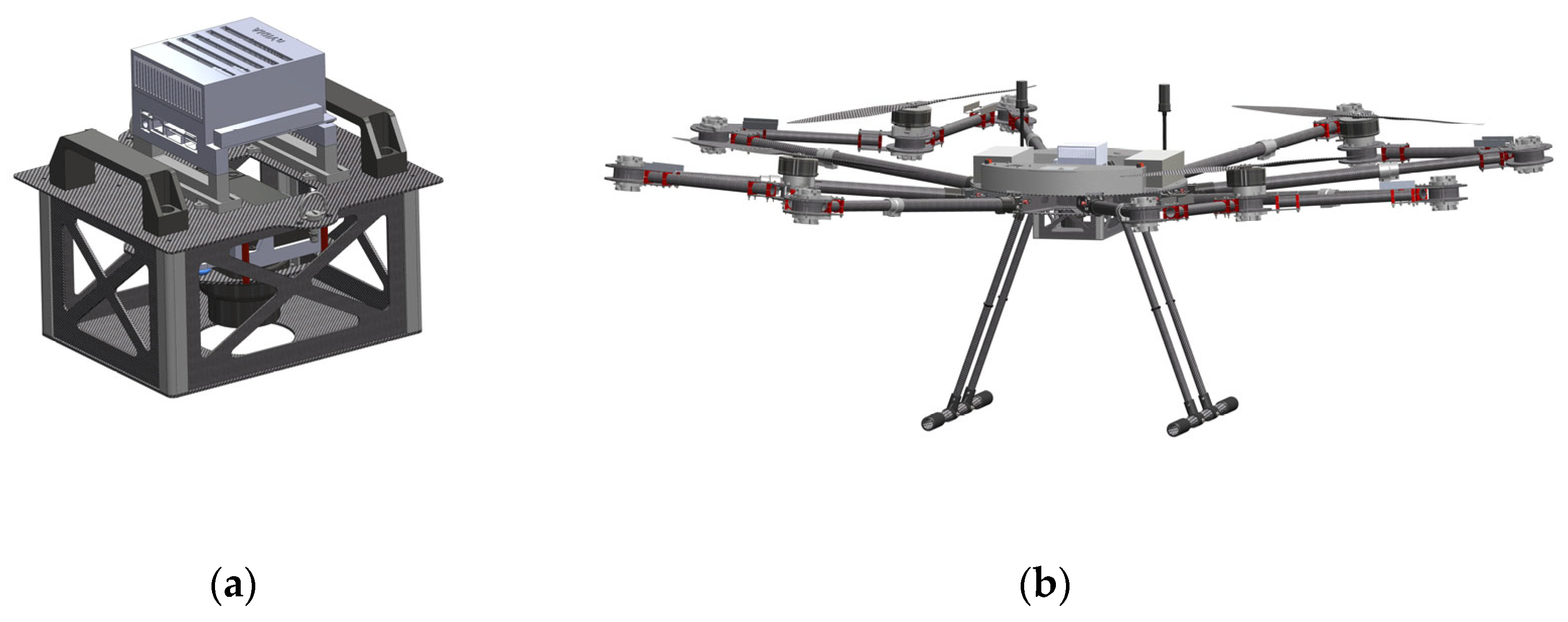
The Sony Alpha A6100 (Sony, Tokyo, Japan) is a mirrorless camera featuring an APS-C sensor, which boasts 24.2-megapixel resolution, providing ample detail and clarity in the captured visuals. Notably, the A6100’s APS-C sensor is significantly larger than those typically found in standard compact digital cameras, enhancing its low-light performance and depth-of-field control capabilities. In addition to conventional photography and videography, the A6100 is well suited for photogrammetry—a technique used to create 3D models and maps from series of 2D images. The camera’s high-resolution 24.2-megapixel APS-C sensor ensures that the resultant 3D models are both detailed and precise. The camera’s compatibility with interchangeable lenses, fast autofocus system, and ability to capture continuous sequences of images make it an ideal choice for photogrammetry tasks. Furthermore, the A6100’s 4 K video recording feature expands its utility, allowing the use of video frames for photogrammetry purposes.
Following that, a comprehensive table of SONY A6100 technical specifications is presented (
Table 3), along with the developed payload enclosure and the corresponding housing configuration (
Figure 16).
6.4.3. RGB and Thermal Sensor [FLIR Duo PRO R and DragonEye2]
The FLIR Duo Pro R (Teledyne FLIR, Wilsonville, OR, USA) is a versatile and compact IR and RGB camera designed for a wide range of high-performance commercial, industrial, and public safety drone applications. Equipped with a built-in IMU (inertial measurement unit), altitude sensors, and GPS receivers, it ensures precise positioning information is embedded directly into the image metadata. This dual-sensor camera combines a high-resolution radiometric thermal imager and a 4 K RGB camera into a single package, enabling professional operators to capture both thermal and visible data in a single flight [
47].
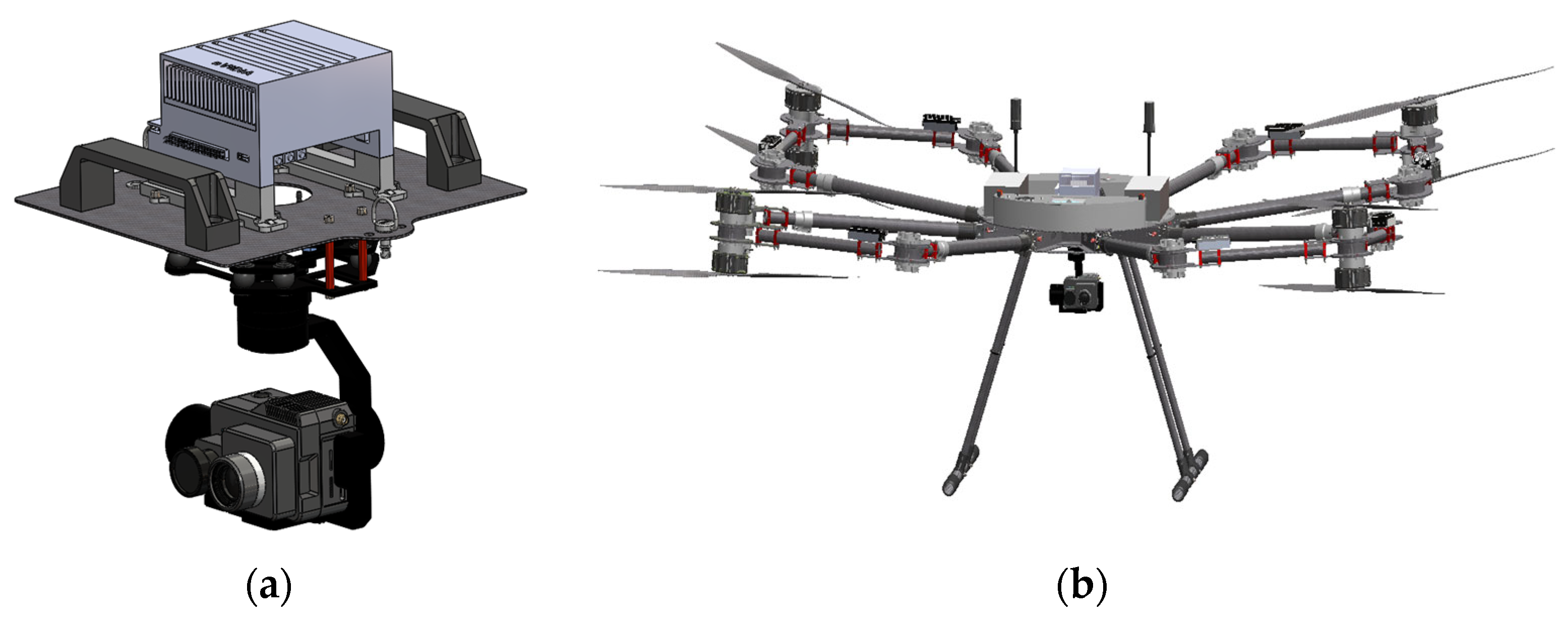
In
Table 4, the technical specifications are provided, while in
Figure 17a, the FLIR Duo Pro R thermal camera is depicted alongside the PIXY F gimbal—a lightweight and compact design tailored specifically for this sensor. The PIXY F gimbal provides a three-axis stabilization system, guaranteeing stable footage under various conditions. With features like a hyper-quick release system and integrated HDMI with multiple I/O interfaces, it facilitates rapid assembly and direct camera signal monitoring, thereby enhancing operational efficiency.
The NextVision DragonEye2 (NextVision, Ra’anana, Israel) is a dual EO/IR stabilized camera that offers unparalleled long-range observation capabilities, making it ideal for monitoring applications. The camera is mounted on an embedded gimbal capable of rotating about the pitch and yaw axes, allowing targeting directly downwards perpendicular to the Earth’s surface. The camera’s low maximum power consumption is an additional advantage that reinforces its desirability. It is paired with the TRIP5 computer module, which accommodates all necessary ports, including HDMI.
The technical specifications of DragonEye2 are detailed in
Table 5, and in
Figure 18 the designed payload case along with the associated configuration.
6.5. System Requirements and Technical Specifications
The three configurations of the PULSAR UAV, as detailed in the matrices below, have been tailored to meet the requirements of each operation. However, the selection of the final configuration must consider not only the mission objectives but also the environmental conditions at the time of the operation. The matrices offer a comprehensive overview, encompassing the system requirements of the UAV (
Table 6) as well as the technical specifications for each configuration (
Table 7,
Table 8 and
Table 9). Moreover, the payloads for each configuration have been chosen to augment the UAV’s capabilities, thus facilitating the accomplishment of its objectives and enhancing its suitability for the intended missions.
As the LiDAR payload was the heaviest among all the options considered, the octocopter configuration was identified as the optimal choice for the demanding task of detailed forest mapping. Its superior thrust-to-weight ratio enables the capture of stable and precise data, which is essential for detailed mapping missions across various terrains, including forests. Moreover, since the LiDAR sensor is the most expensive component selected, the redundancy provided by the octocopter’s eight motors and propellers offers an additional layer of reliability against potential operational failures. Additionally, the larger size of the octocopter is not a barrier, as the LiDAR-equipped drone is required to fly above the tree canopy to conduct detailed forest mapping missions, making it more advantageous than the co-axial design, which has a shorter flight duration.
For the mission involving edge computing and cartographic product generation on the fly, the co-axial configuration of the quadcopter was selected for its balanced performance. This configuration inherently offers greater stability compared with traditional quadcopters, particularly in windy conditions, which is crucial for capturing accurate images—the primary goal of this mission. With two sets of rotors rotating in opposite directions, co-axial configurations provide redundancy in the event of motor or propeller failure, akin to the octocopter configuration. Depending on the environment and use case, flying at lower altitudes may be important to capture detailed imagery of the forest floor and understory vegetation. As a result, the larger size of the octocopter configuration could be prohibitive in such scenarios. The co-axial configuration allows flexibility in flying the UAV with the joints facing outward, enhancing flight control, or with the joints inward, yielding a smaller drone profile.
In tasks such as detection and tracking of elements, the quadcopter configuration excels as the selected choice. Equipped with RGB and thermal sensors, along with onboard processing capabilities, the quadcopter boasts a smaller footprint, facilitating navigation through challenging environments with greater ease than the other two configurations. Although all configurations are relatively easy to deploy, the design of the quadcopter, which necessitates fewer motors attached to the UAV, enables swifter deployment—a critical aspect when the detection of people, animals, vehicles, and hotspots is imperative. Furthermore, the extended flight time afforded by this configuration in respect to the co-axial configuration is vital for the detection and tracking of elements, thereby ensuring robust surveillance and monitoring capabilities.
PULSAR can accommodate all selected payloads in all three configurations. However, the choice of configuration must also consider the environment’s mission, as the UAV’s versatility is rooted in its adaptability to various scenarios. For instance, with the same sensor attached, it can operate as a quadcopter in confined spaces or as an octocopter in windy conditions, providing redundancy for continued safety even in the event of motor failure. This adaptability is facilitated by all components being permanently mounted on the UAV, which, despite the configurations’ similar weights, maximizes user-friendliness and allows users without technical expertise in UAVs to deploy any configuration easily.
As the DJI M600 is a prevalent model in drone applications, its comparison with the PULSAR prototype is inevitable. The DJI M600 has a MTOW of 15.1 kg and can carry a maximum payload of 6 kg, featuring retractable gear for unobstructed camera movement. In contrast, the PULSAR prototype exhibits a larger MTOW, enabling it to carry payloads up to nearly 13 kg in the quadcopter configuration. Additionally, it has been designed for ease of use with a plug-and-play approach for payload integration and landing gear capable of accommodating substantial payloads for future applications, such as firefighting solutions, for example, through incorporating a water tank to address small outbreaks of fires. As described in
Section 4.4, configuration firmware is automatically updated on the UAV without human intervention, aiming to minimize human error via the developed circuit board. Many UAVs offering multiple configurations do not detail how airframe selection is achieved, some require manually uploading the correct firmware each time, which can be challenging without prior experience, while others have multiple controllers on the UAV, one for each configuration, requiring users to connect and disconnect cables from one flight controller to another.
In conclusion, the primary goal in designing this UAV was to facilitate end users in performing a variety of tasks, enabling it to serve as a valuable tool extending beyond the scope of this paper due to its capabilities.
7. Static Structural Analysis
To ensure material strength, a structural analysis should be performed during the design stage of any manufacturing method, thereby minimizing design adjustments in the final product for additional manufacturing. By using physics-based simulations, the number of design–test cycles is dramatically reduced, lowering the likelihood of unexpected design errors occurring during such testing [
48].
Finite element analysis (FEA) or finite element method (FEM) is a widespread structural analysis numerical simulation technique. FEA/FEM, in essence, employs mathematics, specifically partial differential equations (PDEs), to comprehend and evaluate permissible quantities within a structure [
49]. This method yields precise solutions to a given problem while also providing valuable insights into the behavior of physical quantities in the real world [
50]. FEA is useful in predicting and optimizing the structural performance of components to ensure they meet design criteria and perform effectively under a variety of conditions.
Nowadays, these simulations can be executed for performance and reliability analysis using the solid model represented in a CAx tool. Structural analyses within CAx tools are widely used to assess the strength of mechanical systems [
51]. These analyses, which are required prior to the production of mechanical components, aid in the identification of factors that are not readily apparent, ensuring both the efficient use of materials and mechanical robustness. This study presents a structural analysis of the proposed multipurpose UAV during the design stage, performed using the SolidWorks Simulation CAE tool, with a particular emphasis on examining stress and displacement in the mechanical system. Stress analysis involved assessing how internal forces distribute within the material, helping identify areas prone to deformation or failure under different loads, while displacement analysis examined the movement and distortion of the structure in response to applied forces.
7.1. Structural Simulation Results
Ensuring problem-free application is paramount and a critical step towards achieving this was, prior to construction, to calculate the response of the newly designed mechanical system to external loads under operating conditions.
The components examined in the specific context investigated in this paper underwent meshing using the FEA method for static analysis. Meshing is an important step in FEA because it involves the discretization of complex geometries into smaller elements, which affects the accuracy and efficiency of subsequent numerical simulations [
52]. The static analysis starts by applying a force to the relevant regions of the mechanically meshed system equivalent to the anticipated real-world conditions. Static analysis can produce a variety of results, and the particular emphasis in this study was on examining the mechanical system’s stress and displacement.
In this study, the simulation tests were primarily focused on the UAV body, the telescopic arms and carbon tubes, and the aluminum joints, as well as the 3D-printed mechanism to which the drone’s propulsion system is attached. The objective is to ensure their capacity to withstand the thrust force generated by the selected motors.
As previously stated, the primary material used in the development of this UAV was a carbon fiber-epoxy composite (CFRP). Additionally, aluminum arm joints have been used, along with stainless steel bolts. However, since manufacturing with carbon fiber elements might be too complicated, the—3D printed motor quick release mechanism will be developed using Nylon 12 Powder (
Table 10).
As already mentioned, the SolidWorks Simulation CAE tool was used for this analysis. However, the version used did not support simulation of composite materials. Given this limitation and to streamline the analysis without compromising the integrity of the results, the following strategy was adopted: (i) from the beginning, to design the assembly keeping in mind the anisotropic behavior of the CFRP material; (ii) to perform the FEA analysis in sub-assemblies so as to simplify the process; and (iii) to use physical testing to verify the FEA results.
7.1.1. Anisotropic Behaviour of CFRP Material
Even before simulation, during the design phase of the CFRP assemblies, the anisotropic behaviour of the material was taken into consideration. CFRP consists of layers of woven mats of long carbon fibres encapsulated in a resin matrix. The carbon fibres exhibit outstanding tensile strength, enabling the achievement of exceptional mechanical properties in specific loading directions. Consequently, strength is exceptional along the fibre directions. However, the resin matrix itself cannot bear significant loads compared with carbon fibres. Thus, certain loading directions in the CFRP material should be avoided (e.g., tension in a direction vertical to the CF layers does not take advantage of the CF strength and relies only on the relatively weak resin, making the material prone to delamination failure).
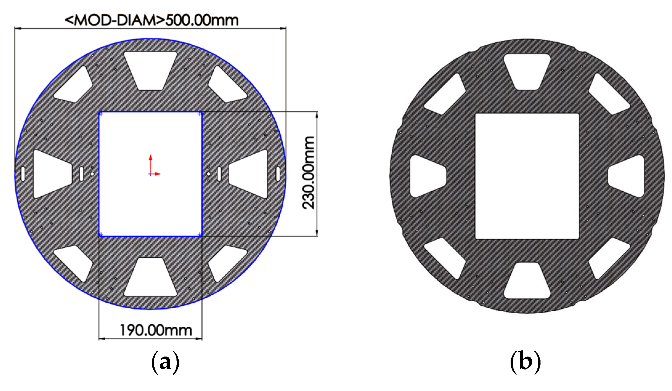
The UAV body structure has been designed to capitalize on the aforementioned characteristics. Two CFRP plates, separated by a distance “d” via the intermediate structure, collaborate to withstand the loads exerted by the UAV arms. The upper plate operates under compression, while the lower plate functions under tension (
Figure 19).
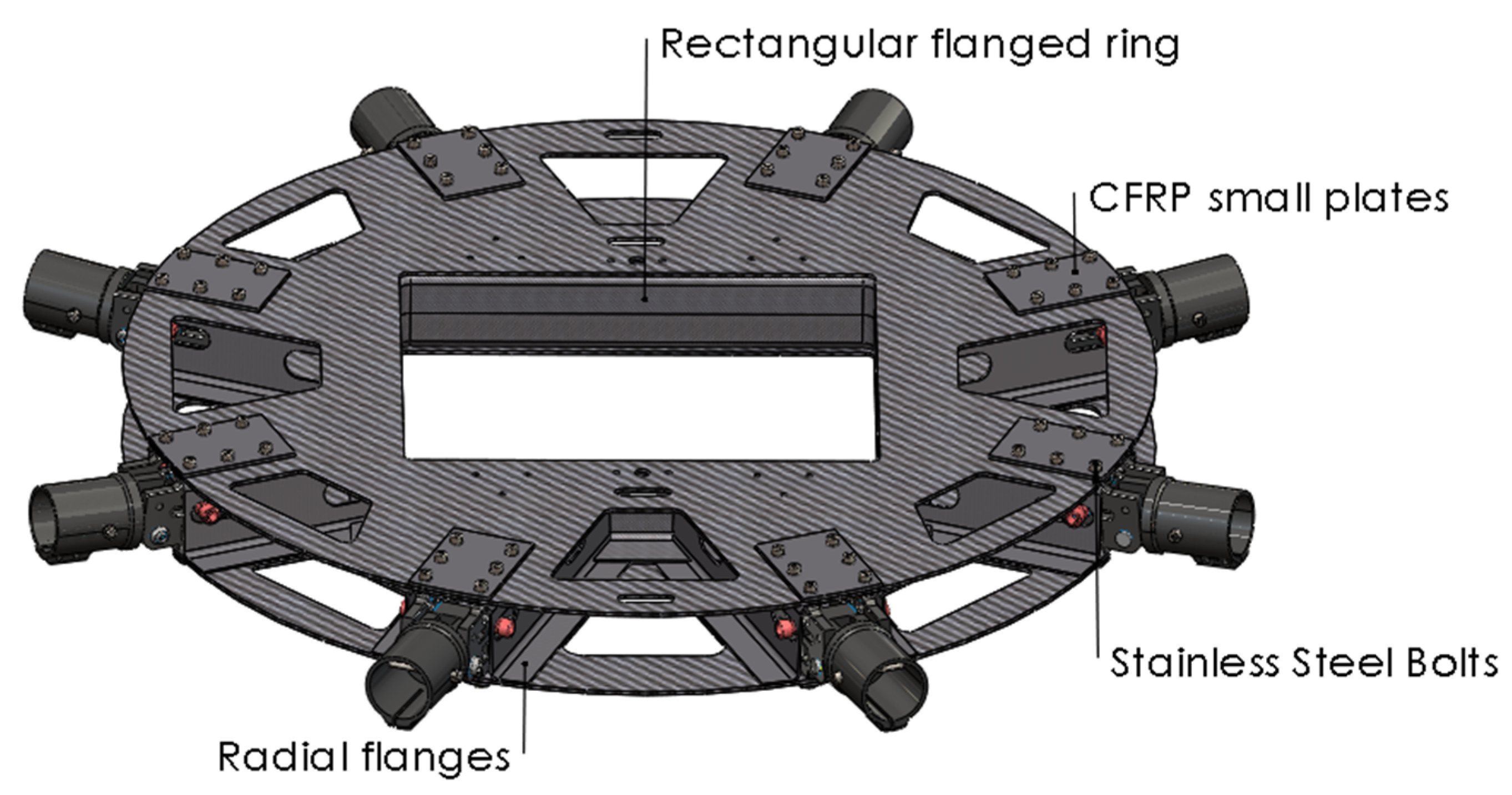
The intermediate structures, comprising one central rectangular flanged ring and eight radial reinforcements, additionally enhance the stiffness of the body assembly (
Figure 7). These CFRP structures were formed with a molding process and high temperature-cured in a vacuum (vacuum bagging). Moreover, they have been designed to have large contact surfaces with the upper and lower plates.
The body assembly is held together with aerospace grade adhesive (taking advantage of the large contact surfaces), to uniformly distribute the loads throughout the structure. Especially for the upper plate, which is subject to compressive forces, the radial reinforcements ensure that no buckling can occur.
Additionally, bolted connections (
Figure 7) reinforce the structure where loads are transferred from the arms to the body via the aluminum joints. Small CFRP plates (also glued) have been added at the areas of the bolted connection as reinforcements to help evenly distribute the arm loads to the body. Moreover, the bolted connections create a compressive state along the axis vertical to the body plane, ensuring that no excessive tensile stress (that can lead to delamination failure) can occur to the resin matrix (especially for the upper plate where compression occurs).
A similar design approach was also applied for the assembly of the arms and joints.
7.1.2. Sub–Assemblies Simulations
For simulation purposes, the total assembly was divided into smaller sub-assemblies, each simulated separately with the appropriate supports and loads applied.
UAV Body
Analysing and estimating the strength of a UAV’s airframe is critical in the development of the UAV. Various forces act on the structural elements of UAVs, including thrust forces from the propulsion system, gravitational forces from the payload, impact loads, and wind-induced loads. The airframe must maintain structural integrity while preserving size and weight under both dynamic and static loading conditions. In essence, the ideal airframe for any UAV should be lightweight while also being robust. The sub-assembly of this UAV was simulated with the following considerations:
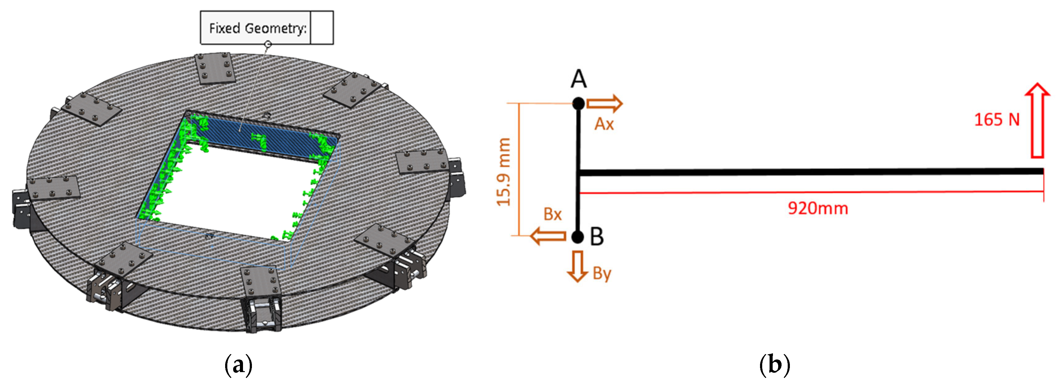
Structural support: A fixed constraint was applied, as shown in
Figure 20a;
Loads: The loads applied to the aluminum joints due to motor thrust were calculated as described in
Figure 20b.
The sketch above (
Figure 20b) is a representation of the UAV arm from the moving part of the aluminum joint (left) to the motor/propeller end where the thrust is applied (right). The maximum thrust from the 32” propeller (100%) is 16.5 kg (
Table 1), which is approximately 165 N. To calculate the reaction forces at points A and B, we apply the formulas for equilibrium on each axis. Following that, the three forces (Ax, Bx, By) are transferred to the stationary part of the aluminum joint, resulting in opposite directions (
Figure 21).
Each of the horizontal forces is applied across two equal surfaces, so half of the force is considered for each surface (9547 N/2 ≈ 4785 N).
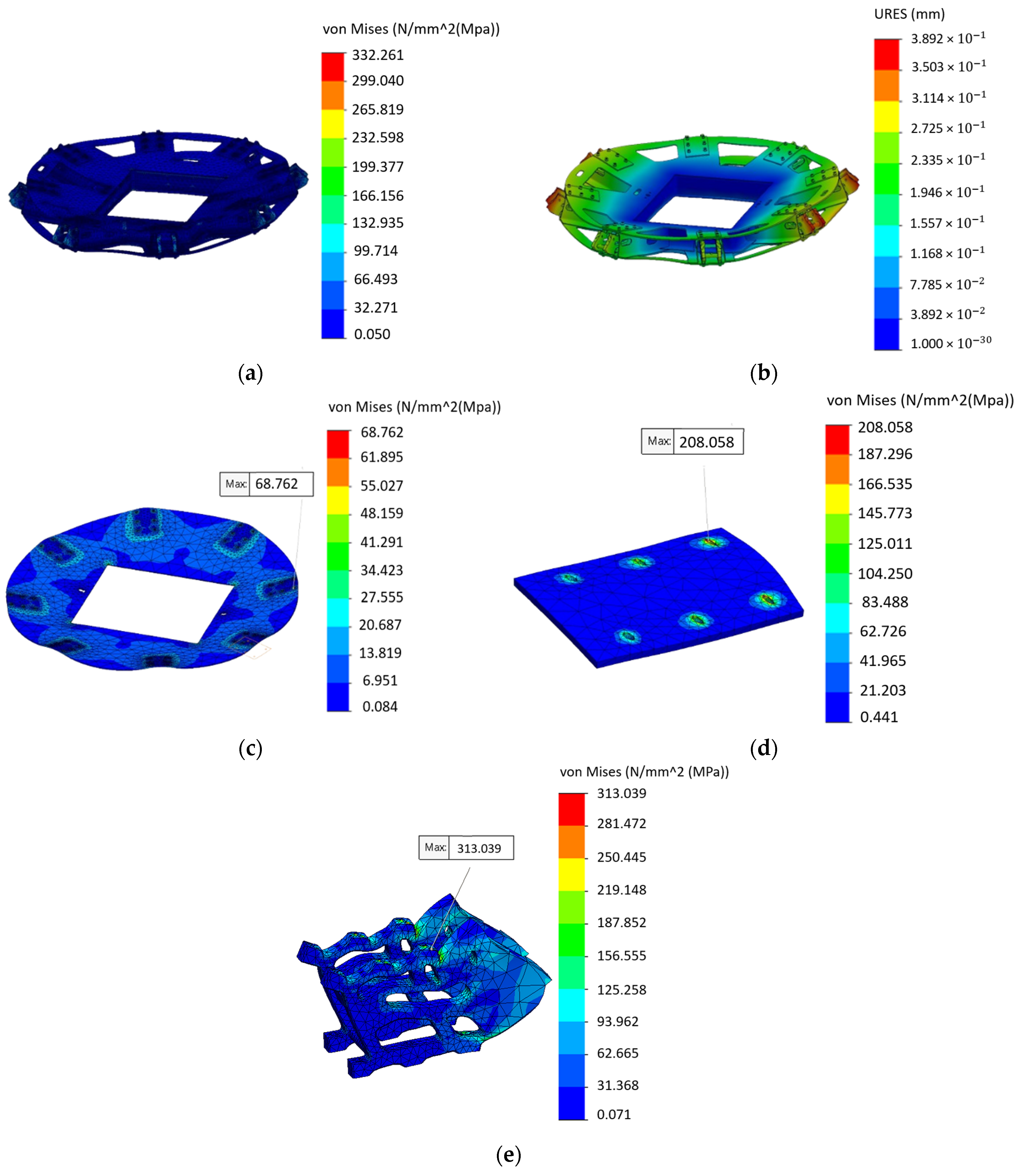
The simulation results for the frame are presented below, with an emphasis on stress and displacement (
Figure 22).
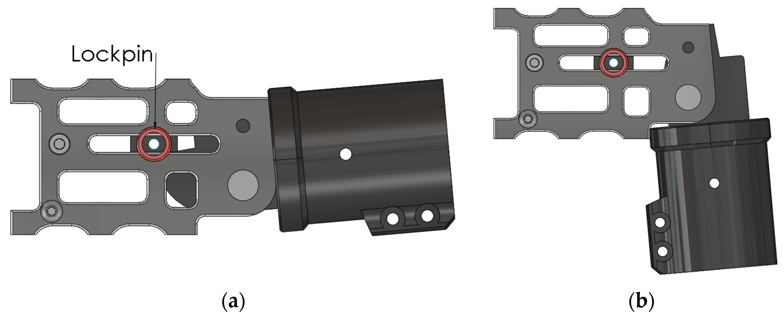
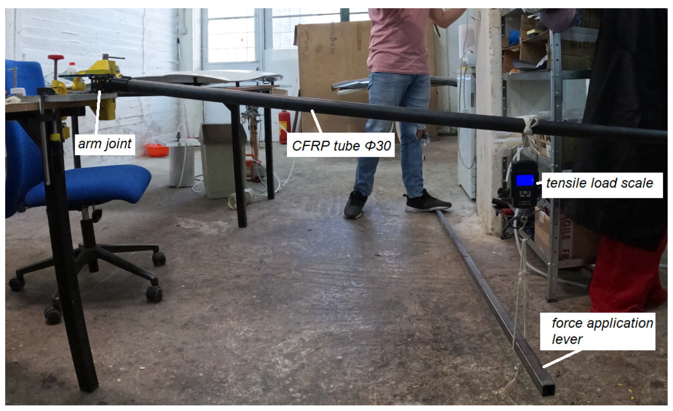
The outcome shows that the stresses and displacements are within acceptable limits. The maximum stress occurs on the outer bolts of the upper side, which are high strength, grade 12.9 (meaning a tensile strength of 1200 MPa and a yield strength of 0.9 × 1200 = 1080 MPa), making them more than adequate to withstand the stresses. The stress on the CFRP upper plate is relatively low, while the maximum stress on the small reinforcing CFRP plate is larger but still within allowable range. Similarly, the maximum stress on the stationary part of the aluminum joint is within the permissible threshold. It is important to highlight that the aluminum joint itself was a purchased part, and its ability to withstand the required stresses has been physically tested from the beginning, prior to integration into the UAV (
Figure 23).
In this test, the arm joint–CFRP tube assembly was repeatedly subjected to a tensile load of up to 18 kg at a distance of 920 mm from the joint. It is important to highlight that the joint was turned upside down to facilitate force application, with the force direction being downwards. Additionally, in this test, the CFRP tube wall thickness was only 1 mm. However, a final wall thickness of 2 mm was selected to minimize deformations.
Telescopic Arms and Joints
Despite the plan for the drone’s motors to operate at half of their maximum thrust across all three configurations, in this study, the system was tested under full power to validate the integrity of the structure. The authors simulated two of the three configurations of the UAV, as these are the two scenarios where the UAV’s arms experience the highest force. Regarding the co-axial quadcopter configuration, the following considerations were taken into account:
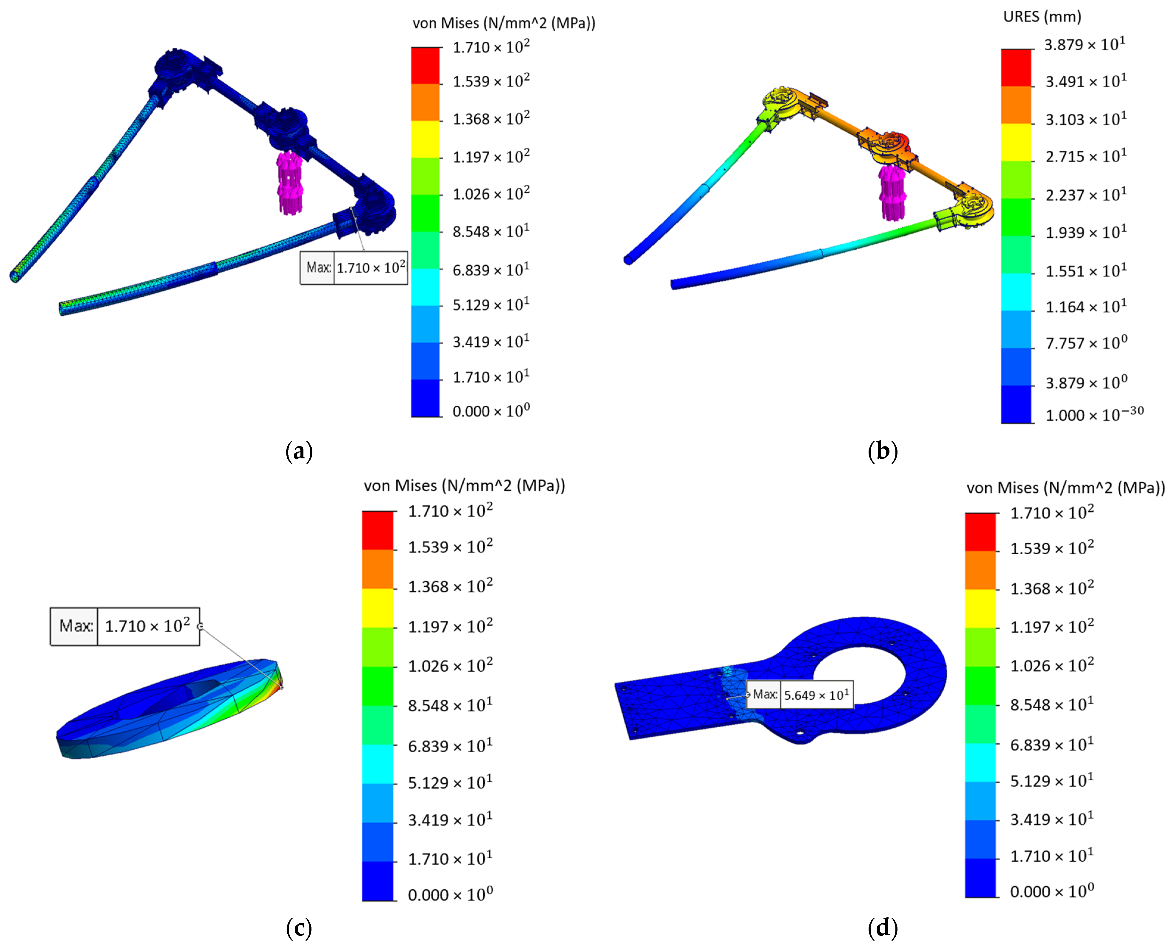
The simulation results for the co-axial quadcopter configuration of this multipurpose UAV are detailed below (
Figure 25).
The simulations indicated that the stresses and displacements were within acceptable limits. The maximum stress of 171 MPa occurred on a stainless-steel washer, whereas the adjacent CFRP plate experienced a much lower maximum stress.
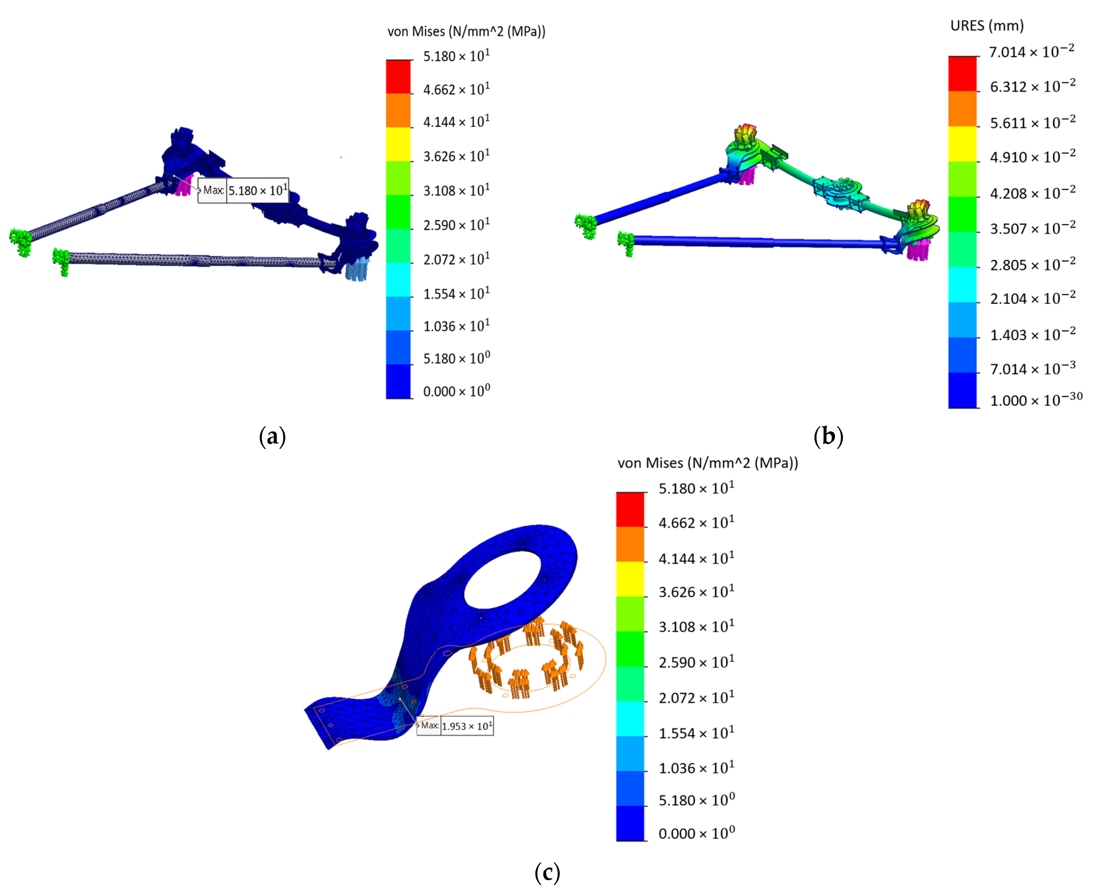
In the case of the octocopter configuration, the same approach for structural support was followed. Regarding the loads, two sets of 141 N loads, corresponding to the maximum thrust of the 30” propellers (
Table 1), were applied to each of the two quick release parts in the same manner as before. All forces were directed upwards. The simulation results for this configuration are showcased below (
Figure 26).
In terms of the mechanism, the parts were exclusively studied for stress and displacement to verify that the components can sustain the full throttle that the motors can provide. Regarding the motor base affixed on the UAV as well as the one affixed on the motor, the considerations applied were as follows:
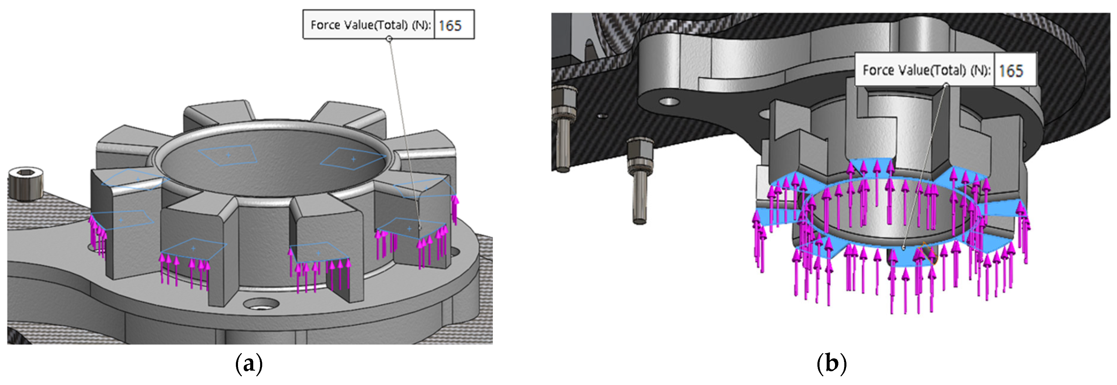
Structural support: four fixed supports were placed on the surface where the bolt heads come in contact with the part (
Figure 27a).
Loads: a total load of 165 N was placed as shown below (
Figure 27b,c).
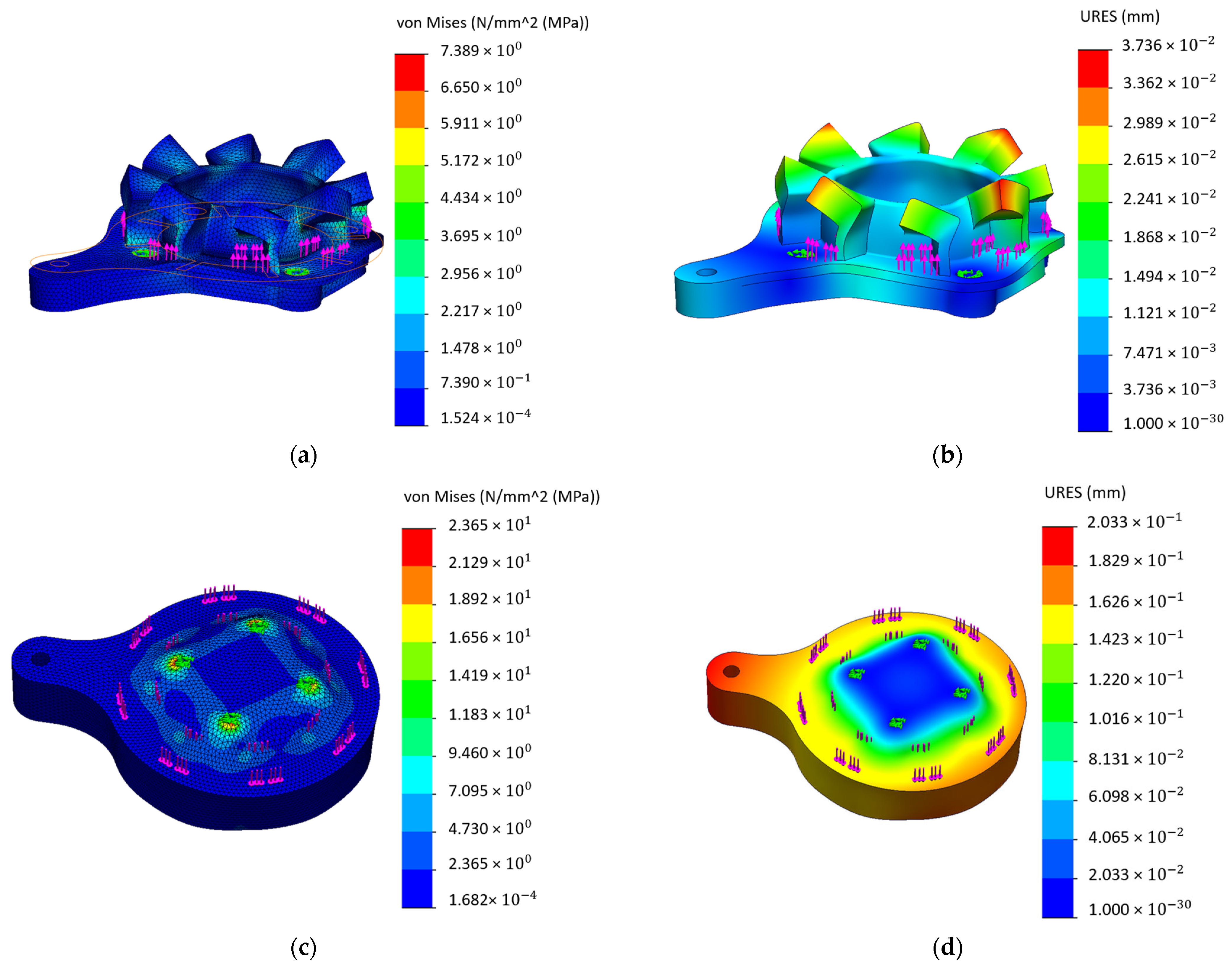
The simulation results for both mechanisms’ parts are shown below (
Figure 28).
The results indicated that the stresses and displacements were within acceptable limits. Physical tests were also conducted on the 3D-printed coupled parts, demonstrating exceptional behavior under a tension load of 40 kg, a torsional load of 8 Nm, and a combined tension load of 30 kg (~300 N) along with a torsional load of 6 Nm. It is important to point out that all three scenarios significantly exceeded the maximum expected loads.
After extensive simulations,
Table 11 summarizes the results obtained, providing a detailed overview of system performance and behaviour. This facilitates comparison with the mechanical properties of the materials involved, enhancing understanding of real-world scenarios. As can be inferred, the generated loads are lower than the values of the mechanical properties.
8. Conclusions
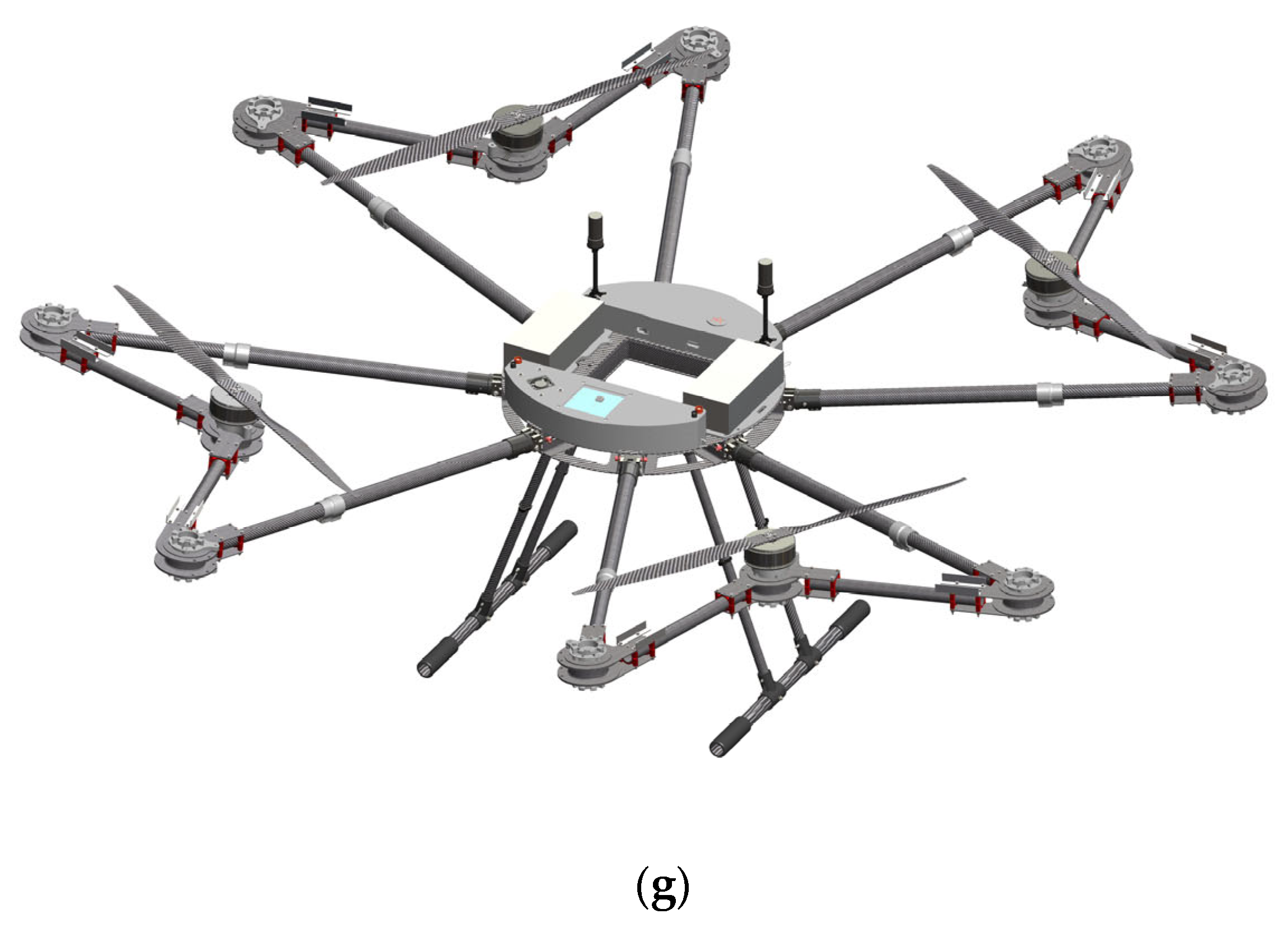
This paper offers a comprehensive exploration of the design and modelling of a versatile, reconfigurable multi-rotor UAV. Its telescopic arms can seamlessly transition into quadcopter, octocopter, and co-axial quadcopter formations without necessitating any mechanical alterations to the fixed body structure. This adaptability, as well as the ability to accommodate various payloads, empowers end users to customize the UAV’s performance to meet diverse mission profiles in wildfire management.
Continuing the examination of structural aspects of the UAV, the simulation results, as shown in the figures and the tables above, provide a detailed insight into the stress analysis of the mechanical components. The findings show that the selected carbon fibre materials, aluminium joints, stainless steel bolts, and Nylon 12performed admirably, even under the demanding conditions of full power operation for the drone. Stress levels were analyzed and found to consistently remain within the mechanical property values, thereby demonstrating the robust structural integrity of the components.
Furthermore, an examination of displacement patterns revealed intriguing insights. The displacement in components directly connected to the motors was noticeably low, remaining well within the operational standards’ permissible limits. This observation is especially important because it ensures that structural deformations in these critical areas do not pose any operational issues for the drone system. These findings confirm the system’s resilience and ability to withstand the dynamic forces encountered during operation, due to the careful selection of materials and overall structural design of the UAV. In conclusion, the paper highlights the exceptional adaptability and structural integrity of the UAV, showcasing its potential impact on diverse applications, particularly in wildfire management.

