Article

Channel Knowledge Map Construction Based on a UAV-Assisted Channel Measurement System

1
The Key Laboratory of Dynamic Cognitive System of Electromagnetic Spectrum Space, College of Electronic and Information Engineering, Nanjing University of Aeronautics and Astronautics, Nanjing 211106, China
2
Department of Electrical Engineering, Qurtuba University of Science and Information Technology, Dera Ismail Khan 29140, Pakistan
*
Author to whom correspondence should be addressed.
Drones 2024, 8(5), 191; https://doi.org/10.3390/drones8050191
Submission received: 13 April 2024 / Revised: 6 May 2024 / Accepted: 9 May 2024 / Published: 11 May 2024

Abstract

:
With the fast development of unmanned aerial vehicles (UAVs), reliable UAV communication is becoming increasingly vital. The channel knowledge map (CKM) is a crucial bridge connecting the environment and the propagation channel that may visually depict channel characteristics. This paper presents a comprehensive scheme based on a UAV-assisted channel measurement system for constructing the CKM in real-world scenarios. Firstly, a three-dimensional (3D) CKM construction scheme for real-world scenarios is provided, which involves channel knowledge extraction, mapping, and completion. Secondly, an algorithm of channel knowledge extraction and completion is proposed. The sparse channel knowledge is extracted based on the sliding correlation and constant false alarm rate (CFAR) approaches. The 3D Kriging interpolation is used to complete the sparse channel knowledge. Finally, a UAV-assisted channel measurement system is developed and CKM measurement campaigns are conducted in campus and farmland scenarios. The path loss (PL) and root mean square delay spread (RMS-DS) are measured at different heights to determine CKMs. The measured and analyzed results show that the proposed construction scheme can effectively and accurately construct the CKMs in real-world scenarios.

1. Introduction

Due to high flexibility and low cost, unmanned aerial vehicles (UAVs) have been widely used in various civil and military fields, such as aerial base stations, emergency communication, and post-disaster relief, etc. [1,2,3,4]. A deep understanding of channel knowledge in the UAV communication environment is of great significance for the reliable UAV-related communication [5,6,7,8,9,10,11]. Channel measurement is an important method to obtain channel knowledge in real communication scenarios [12,13,14,15,16,17]. However, it can only obtain the channel knowledge at a specific location, and is not suitable for the large-scale propagation environment. A channel knowledge map (CKM) [18] or channel feature map (CFM) [19] displays the channel knowledge visually in the form of a heat map, including path loss (PL), root mean square delay spread (RMS-DS), channel path knowledge, etc. As an important bridge connecting the environment and the propagation, it is widely used in positioning optimization [20,21], path planning [22], beamforming [23,24] and network layout [25,26], etc.
Several studies have addressed CKM, as indicated by references [23,25,27,28]. For example, the authors in [23] used the inverse distance weighted (IDW) approach to complete the missing simulation data, and constructed a channel path map (CPM). In [25,28], the authors used the k-nearest neighbor (KNN) method and the Kriging interpolation approaches to generate the missing data in the simulation, and then constructed a channel gain map (CGM). In [27], the author constructed a channel shadow map (CSM) based on a spatial correlation approach. The radio map or spectrum map, which is one of the typical applications of CKM [29,30,31,32], can display the spatial distribution of the received signal strength (RSS) of a single frequency point in the measurement scenario in the form of a heat map, so that the electromagnetic radiation of the measurement scenario can be directly observed.
However, it should be noted that the above CKMs and spectrum maps are usually constructed by using the simulated data [23,25,28,30,33], which is quite different from the real situation. Moreover, the measurement system is relatively simple, which can only obtain the channel knowledge of a single transceiver position [29,31]. Second, most of the current research focuses on CGM, and only [18] constructs the CPM of the strongest path, which is not enough for the research on channel characteristics.
In order to fill these research gaps, a CKM construction scheme is proposed, which is based on a self-developed UAV-assisted channel measurement system; the main contributions and novelties are summarized as follows.
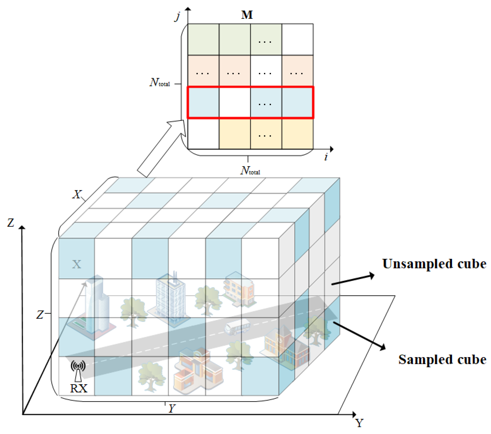
  • A three-dimensional (3D) channel knowledge construction scheme in real-world scenarios is provided and implemented. The measurement scenario is divided into a 3D grid region and the CKM can be expressed by a 3D matrix. The channel knowledge along the flight trajectories is obtained by a self-developed channel measurement system. Then, the sparse CKM matrix is completed based on the spatial correlation of the channel characteristics.
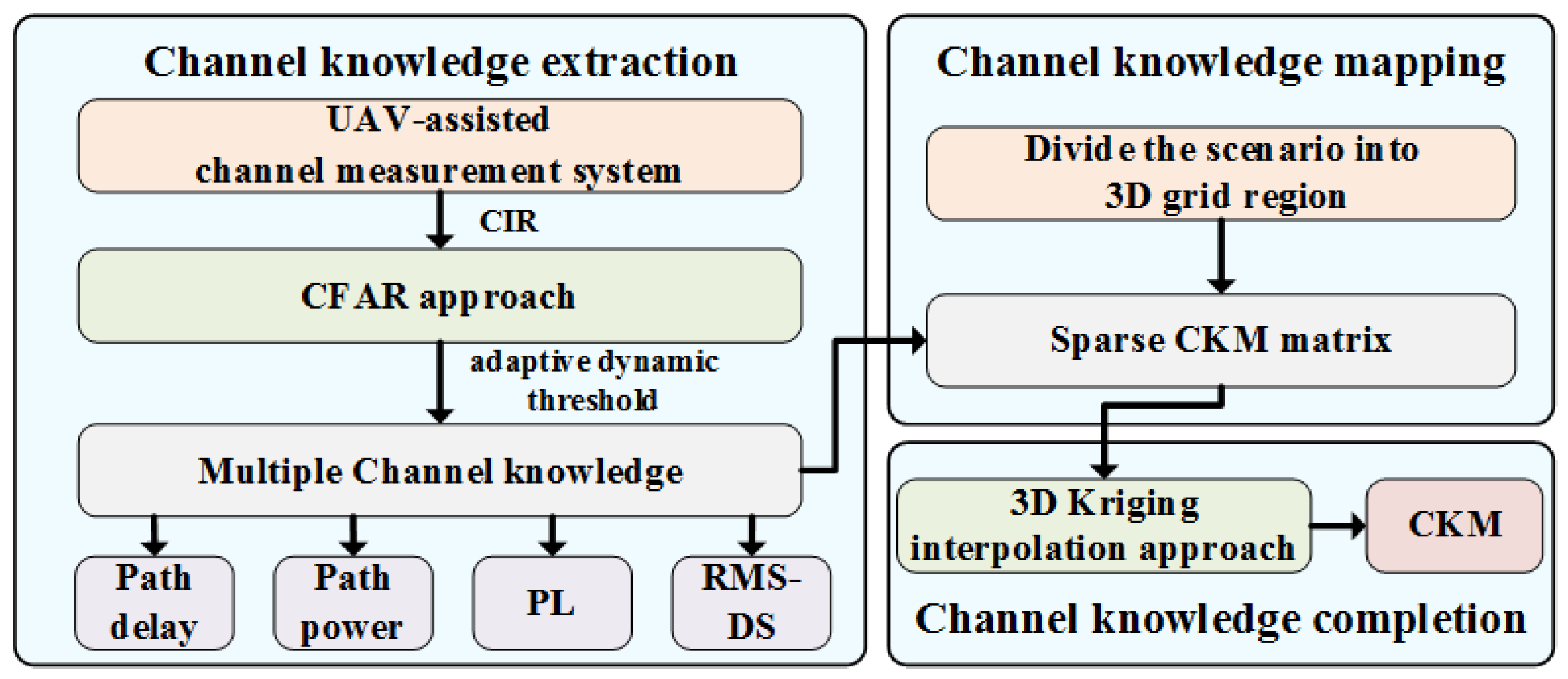
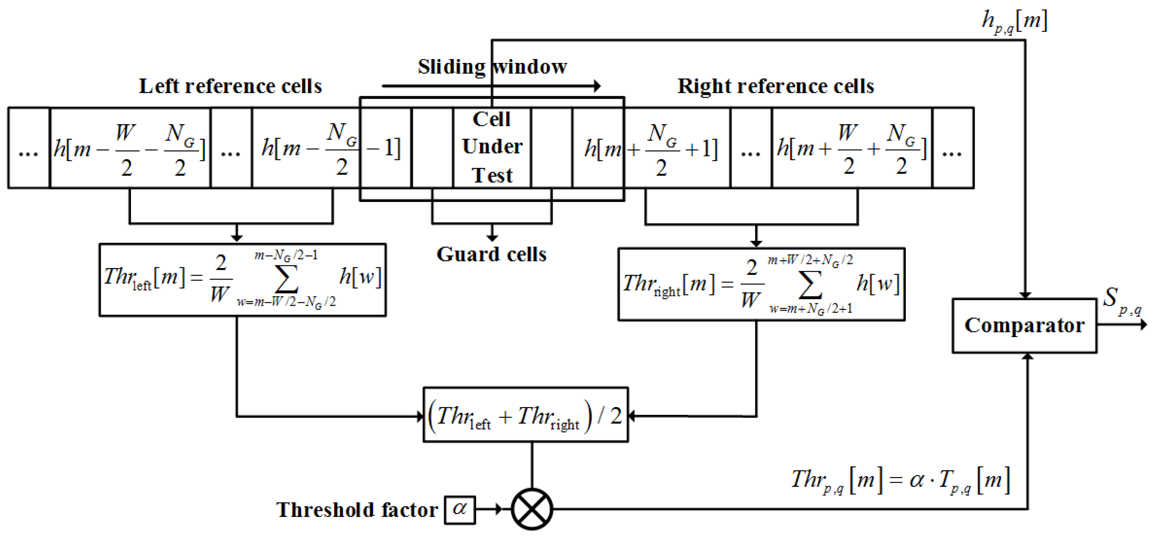
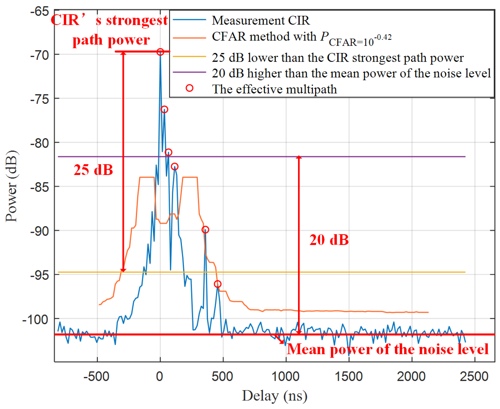
  • An algorithm for extracting and completing channel knowledge is proposed. The time-domain channel measurement idea is adopted to obtain the channel impulse response (CIR). An adaptive dynamic noise threshold approach is proposed based on the constant false alarm rate (CFAR) to improve the extraction accuracy in real-world scenarios. Due to the limitation of measurement time and cost, the CIR and channel knowledge are only measured along the UAV trajectories. The channel knowledge in other positions is completed by a 3D Kriging interpolation approach.
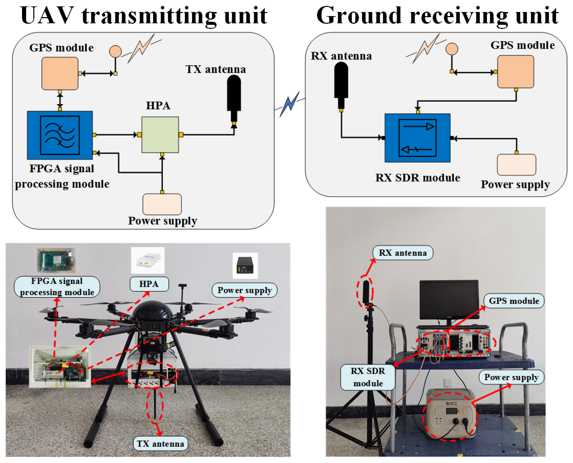
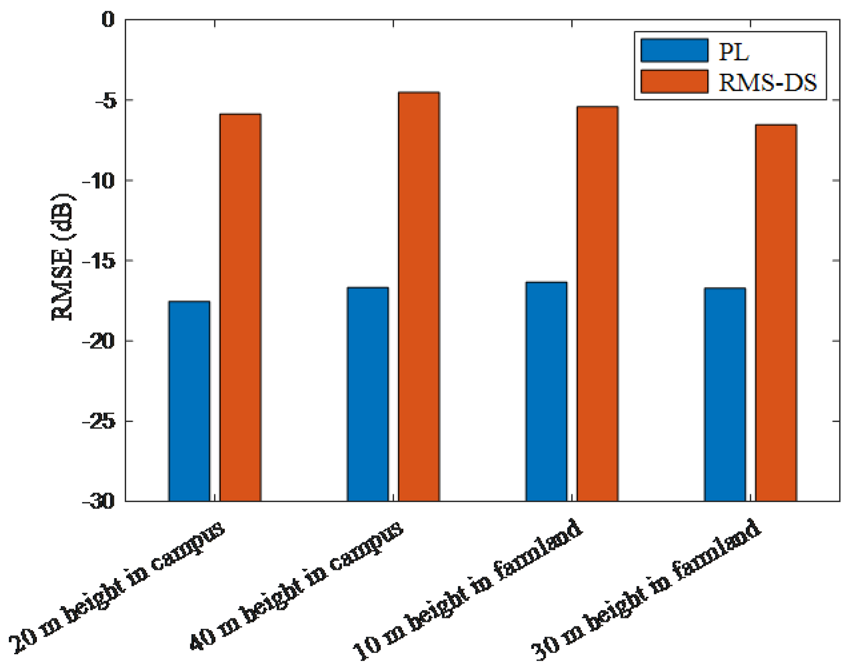
  • A UAV-assisted channel measurement system is developed and applied to measure the CKMs in the real-world scenarios. The system consists of a UAV transmitting unit and a ground receiving unit. CKM measurement campaigns are conducted in two typical scenarios of campus and farmland, and CKMs of PL and RMS-DS at two different heights under these two scenarios are constructed. The accuracy of the constructed CKMs is verified by the root mean square error (RMSE).
The rest of this paper is organized as follows. In Section 2, a mathematical model of CKM is proposed, and then the provided construction scheme is given. In Section 3, the algorithm of channel knowledge extraction and completion is proposed. In Section 4, a UAV-assisted channel measurement system is developed, and then the CKMs in campus and farmland scenarios are measured. Finally, conclusions are drawn in Section 5.

2. 3D Channel Knowledge Mapping

A 3D grid model of CKM is given in Figure 1. The measurement scenario is divided into a 3D grid region composed of N total = X × Y × Z cubes, assuming that the average value of the channel knowledge collected in a cube is the estimated value of the channel knowledge in the cube region. At the same time, the accuracy of constructing CKM improves with the increase in the number of cubes. In this paper, we define the 3D grid mathematical model of CKM to be composed of the channel knowledge between any two cubes in this 3D cube region. Then, the 3D grid model of CKM can be represented as a N total × N total channel knowledge matrix M ; the elements m i , j of the M can be represented as the channel knowledge between the i th i = 1 , 2 , , N total cube x i , y i , z i and the j th j = 1 , 2 , , N total cube x j , y j , z j
m i , j = I i , j ,   i j Ø ,   i = j
where I i , j represents the multiple channel knowledge between the ith cube and the jth cube, including PL, shadow fading, channel gain, path delay, power, angle, RMS-DS, and so on. When i = j , the two cubes coincide and no channel knowledge exists. In this paper, the CIR between two cubes is used to extract the multiple channel knowledge, which can be represented by a tensor I . Figure 1 shows the representation of the 3D grid model of CKM when the receiver (RX) is fixed at a particular location in the measurement scenario. The “sampled cube” represents the channel knowledge extracted by simulation or channel measurement, and the “unsampled cube” represents the unmeasured location. Due to the huge amount of data in actual channel measurement, we use the sparse sampled cubes to complete the unsampled cubes and construct the entire 3D CKM. When the RX is fixed at the cube i, the CKM is represented as the ith row in the channel knowledge matrix M .
Figure 2 shows the complete flow chart of the CKM construction scheme presented in this paper, including the three parts: channel knowledge extraction, mapping, and completion. In the channel knowledge extraction part, we first use a UAV-assisted channel measurement system to conduct the CKM measurement campaign in the measurement scenario, extract the CIR at sparse locations in the measurement scenario in real time based on the sliding correlation approach, and then generate the adaptive dynamic noise threshold based on the CFAR approach to extract effective multiple channel knowledge, including path delay, path power, PL, and RMS-DS, etc. In the channel knowledge mapping part, we divide the measurement scenario into a 3D grid region, and give the discretization matrix of the 3D CKM, then map the channel knowledge at the corresponding sparse location to the CKM matrix elements. In the channel knowledge completion part, we use the Kriging interpolation approach to complete the sparse CKM matrix, and finally construct the CKM.

3. Channel Knowledge Extraction and Completion

3.1. Channel Impulse Response Extraction

The CIR is an important mathematical model containing the multiple channel knowledge of each propagation path [34,35,36]. Therefore, the CIR between the transmitter (TX) and RX is used to extract the multiple channel knowledge in this paper, where the received signal of the RX antenna can be represented as a model of the transmitted signal and the wireless channel
y ( t ) = x ( t ) H P × Q ( t , τ , φ , θ )
where P and Q are the number of TX and RX antennas, respectively, ∗ represents convolution operation, x ( t ) = [ x 1 ( t ) , , x p ( t ) , , x P ( t ) ] and y ( t ) = [ y 1 ( t ) , , y q ( t ) , , y Q ( t ) ] are the vector of TX signal and the vector of RX received signal, respectively, H P × Q ( t , τ , φ , θ ) is a P × Q matrix, where h p , q ( t , τ , φ , θ ) is the CIR between the pth TX antenna and the qth RX antenna, which can be expressed as
h p , q ( t , τ , φ , θ ) = l = 1 L α l ( t ) e j ψ l δ ( τ τ l ( t ) ) · δ ( φ φ l TX ( t ) ) · δ ( φ φ l RX ( t ) ) · δ ( θ θ l TX ( t ) ) · δ ( θ θ l RX ( t ) )
where α l and τ l are amplitude and delay of lth path, ψ l is phase of lth path, φ l TX and φ l RX are azimuth angle of departure (AAoD) and azimuth angle of arrival (AAoA) of lth path, respectively, θ l TX and θ l RX are elevation angle of departure (EAoD) and elevation angle of arrival (EAoA) of lth path, respectively.
The time-domain channel measurement method based on sliding correlation has the advantages of strong real-time performance and high precision, and the CIR can be extracted effectively by using the good auto-correlation of the sounding sequence. In this paper, the channel measurement method based on the sliding correlation is used to extract the CIR, where the results of the sliding correlation operation of the pth TX antenna and the qth RX antenna can be expressed as
ρ p , q ( t , τ , φ , θ ) = y q ( t ) x p ( t ) = k = 1 P h k , q ( t , τ ) x k ( t ) x p ( t )
where ⊗ represents the sliding correlation operator. Furthermore, (4) denotes that the sliding correlation result ρ p , q ( t , τ , φ , θ ) of the qth RX antenna is the superposition of CIRs between the P TX antennas and the qth RX antenna. Therefore, in order to accurately extract the CIR between the pth TX antenna and the qth RX antenna, we design a sounding sequence with low cross-correlation.
The Zadoff-Chu (ZC) sequence has good auto-correlation, low cross-correlation, flat power spectral density and low peak factor. Therefore, the ZC sequence as sounding sequence can obtain better measurement performance [37]. We use the ZC sequence as the sounding sequence in this paper. The low cross-correlation between the different root indices of the ZC sequence is used to design the measurement. Therefore, the sounding sequence of different TX antennas can be expressed as
x r n = exp j π r n ( n + 1 ) N ZC
where j is the imaginary number unit, n = 0 , 1 , , N ZC 1 , N ZC is odd and represents the length of the ZC sequence, r 1 , 2 , , N ZC 1 is the root index of the ZC sequence, where r and N ZC are mutually prime, x r n represents the ZC sequence with root index r. Taking the qth RX antenna as an example, the received signal is the superposition of the transmitted signal of the P TX antennas. In order to accurately extract the CIR between the pth TX antenna and qth RX antenna, we make use of the low cross-correlation between the ZC sequences with different root indices, and use the local sequence x p r n to carry out sliding correlation operation on the received signal. The CIR between the qth RX antenna and the pth TX antenna can be accurately extracted, while other CIRs can be effectively suppressed. Therefore, (4) can be further expressed as
ρ p , q r n , τ , φ , θ = y q n x p r n = N ZC h p , q n , τ , φ , θ
where ρ p , q r n , τ , φ , θ , h p , q n , τ , φ , θ , x p r n and y q n are the discrete form of ρ p , q ( t , τ , φ , θ ) , h p , q ( t , τ , φ , θ ) , x p r ( t ) , and y q ( t ) , respectively. In particular, the CIR between the pth TX antenna and the qth RX antenna can be finally expressed as
h p , q n , τ , φ , θ = y q n x p r n / N ZC
Finally, according to the obtained CIR, the multiple channel knowledge can be further extracted, in which the multiple channel knowledge between the i th i = 1 , 2 , , N total cube and the j th j = 1 , 2 , , N total cube in (1) can be expressed as a tensor
I i , j = τ l , α l , φ l TX , φ l RX , θ l TX , θ l RX l = 1 L

3.2. Channel Knowledge Extraction

Equation (7) is based on the received signal superimposed with noise to obtain the CIR. Therefore, the effective channel knowledge in the CIR needs to be accurately extracted from the noise. The traditional approach of setting the constant noise threshold requires choosing the threshold based on a lot of prior knowledge. At present, many approaches have been adopted, For example, the noise threshold in [38] was 25 dB lower than the CIR’s strongest path power. In [39], it was 20 dB higher than the mean power of the noise level. In [40], it was 20% of the CIR’s strongest path power. In [41], it was −35 dB, based on the relative power of the reflection from building. These approaches may cause the multipath with a smaller power value to be missed or confuse some noise for an effective multipath, resulting in errors when extracting effective channel knowledge.
The CFAR approach is a common target detection and tracking algorithm in the radar field. Its main function is to detect target signals in the background noise. The CFAR approach dynamically adjusts the detection threshold according to the noise and maximizes the detection probability of the target signal under the condition of a constant false alarm probability. Therefore, using the CFAR approach to set the noise thresholds in CIR to extract the channel knowledge has also been studied [42,43,44]. Figure 3 shows the principle of generating an adaptive noise threshold using the mean level CFAR (ML-CFAR) approach. Firstly, it determines the number of guard cells, which can keep adjacent cells under test from interfering with each other. Then, it calculates the average of the reference cells on the left and the reference cells on the right as the background noise power level and multiplies them with the threshold factor. As the sliding window moves, the adaptive noise threshold is calculated. The CIR value is compared with the noise threshold to extract accurate channel knowledge.
Firstly, we set the length of the reference cells to W and the number of guard cells to N G . Then, the background noise power level of the cell under test can be expressed as the mean level of the power value of the reference cells
T p , q [ m ] = 1 W w = m W 2 N G 2 m N G 2 1 h p , q w + w = m + N G 2 + 1 m + W 2 + N G 2 h p , q w
where m = 1 + W / 2 + N G / 2 , , N ZC W / 2 N G / 2 . The threshold factor depends on the length of the reference unit and the probability of the false alarm
α = W · P CFAR 1 W 1
where P CFAR is the false alarm probability. It can be seen from (10) that the false alarm probability is only related to W and α , and has nothing to do with the noise of the actual measurement. Therefore, the accuracy of the channel knowledge extraction can be maximized when the false alarm probability remains unchanged. Finally, the adaptive noise threshold of the CIR can be expressed as the product of the background noise power level and the threshold factor
T h r p , q m = α · T p , q m
When the CIR value is greater than the adaptive noise threshold, the effective multipath will be extracted, including the corresponding delay and power, where the effective multipath in the CIR can be expressed as
S p , q = τ l , α l peak ( h p , q [ m ] ) > T h r p , q [ m ]
where τ l and α l are the delay and amplitude of the lth effective multipath, respectively, and peak ( · ) is the peak value. We use the CIR obtained from the actual measurement for comparison and verification. Figure 4 shows that the adaptive noise threshold generated by the ML-CFRA method at P CFAR = 10 0.42 , W = 36 and N G = 2 is compared with the constant noise threshold in [38,39]. It can be seen that the use of a constant noise threshold may lead to some multipaths with low power not being missed, resulting in measurement errors.
After extracting the delay and amplitude of each effective multipath, the important channel characteristics can be further calculated. PL is the energy loss caused by the signal’s own energy diffusion and the climate environment in the propagation process, which can be expressed as
P L = 10 log 10 l = 1 L α l 2
RMS-DS is one of the important channel characteristics in the process of communication system design, which can be expressed as
R M S D S = l = 1 L τ l τ ¯ 2 α l 2 l = 1 L α l 2
where τ ¯ represents the power-weighted average of all delays, which can be further expressed as
τ ¯ = l = 1 L τ l α l 2 l = 1 L α l 2
Finally, we define the multiple channel knowledge between the ith cube and the jth cube in this paper as
I i , j = P L i , j , R M S D S i , j
where P L i , j and R M S D S i , j denote the PL and RMS-DS between the ith cube and the jth cube.

3.3. Channel Knowledge Completion and Prediction

In this paper, we use the multiple channel knowledge of the sparse sampled cubes in the measurement scenario to estimate the multiple channel knowledge of the unsampled cubes. Since the channel knowledge of the adjacent cube has certain correlation, the Kriging interpolation approach can be used to predict the channel knowledge at the unsampled cubes. By calculating the semi-variance and the Euclidean distance between any two different sampled cubes, the Kriging interpolation approach fits the semi-variance function, and then calculates the semi-variance between the unknown sampled cube and all sampled cubes. Finally, the channel knowledge of the unknown sampled cube is estimated after the weight is obtained [25,29]. The multiple channel knowledge of an unsampled cube can be expressed as the weighted average of the channel knowledge of the sampled cubes as
I ^ 0 = u = 1 N ω u I u
where I ^ 0 is the channel knowledge estimated value at the unsampled cube, I u is channel knowledge measured value at the uth u = 1 , 2 , , N sampled cube, N is the number of sampled cubes, ω u is the weight factor. The weight factors can be determined through an optimal problem with nonlinear constraints as
min ω k Var I ^ 0 I 0 s . t .   u = 1 N ω u = 1
where Var ( · ) expresses variance. In addition, to simplify this problem, we set J = Var I ^ 0 I 0 , which can be further expressed as
J = Var u = 1 N ω u I u I 0 = Var u = 1 N ω u I u + Var I 0 2 Cov u = 1 N ω u I u , I 0 = u = 1 N v = 1 N ω u ω v Cov I u , I v + Cov I 0 , I 0 2 u = 1 N ω u Cov I u , I 0
At the same time, to further solve this problem, we define that the semi-variance between the uth sampled cube and the vth v = 1 , 2 , , N sampled cube can be expressed as
γ u v = 1 2 Var I u I v = 1 2 E I u E I u 2 + 1 2 E I v E I v 2 E I u E I u I v E I v
where E · expresses expectation. Furthermore, (19) can be obtained after further simplification as
J = u = 1 N v = 1 N ω u ω v σ 2 γ u v + σ 2 γ 00 2 u = 1 N ω u σ 2 γ u 0 = 2 u = 1 N ω u γ u 0 u = 1 N v = 1 N ω u ω v γ u v γ 00
In order to solve for the optimal weight under the condition constraints, we use the Lagrange multiplier method to solve this problem, and first construct the objective function as
L ( ω u , ϕ ) = J + 2 ϕ u = 1 N ω u 1
where ϕ denotes the Lagrange multiplier. In order to solve the optimal weight, the objective function L takes the partial derivative with respect to ω u and ϕ , respectively. Then, they are set equal to 0, and the problem can be further expressed in matrix form as
γ 11 γ 12 γ 1 N 1 γ 21 γ 22 γ 2 N 1 γ N 1 γ N 2 γ N N 1 1 1 1 0 ω 1 ω 2 ω N ϕ = γ 10 γ 20 γ N 0 1
where γ u 0 represents the semi-variance of the uth sampled cube and unsampled cube. At the same time, the Kriging interpolation approach believes that there is a functional relationship between the semi-variance γ and Euclidean distance d of two cubes. We obtain the semi-variance function by fitting the semi-variance and Euclidean distance between all cube shapes, which can be expressed as
γ = γ d
where the Euclidean distance d u v between the uth sampled cube and the vth sampled cube can be expressed as d u v = x u x v 2 + y u y v 2 + z u z v 2 . Finally, after calculating the semi-variance between the unsampled cubes and all sampled cubes by using the semi-variance function, the optimal weight ω u * of Kriging interpolation can be obtained. Then, by substituting the ω u * into (17), the multiple channel knowledge of the unsampled cube can be estimated.

4. CKM Measurement Results and Analysis

4.1. Measurement System and Campaign

The UAV-assisted channel measurement system is composed of the UAV transmitting unit and the ground receiving unit, and the composition block diagram is shown in Figure 5. The UAV transmitting unit consists of a hexcopter, a field programmable gate array (FPGA) signal processing module, a high-power amplifier (HPA), a global positioning system (GPS) module, an omnidirectional TX antenna, and a portable power supply. The FPGA signal processing module generates the ZC sequence with adjustable length and carrier frequency. After that, the signal is amplified by the HPA, and transmitted by the omnidirectional TX antenna; the portable power supply is responsible for powering the FPGA signal processing module and the HPA. The ground receiving unit is composed of an RX software radio (SDR) module, a GPS module, an omnidirectional RX antenna, and a power supply. After receiving the signal from the omnidirectional RX antenna, the RX SDR module performs sliding correlation calculation to extract the CIR in real time and store it. The GPS module uses the pulse per second (PPS) signal to trigger the TX transmitting signal and the RX receiving signal at the same time to realize the synchronization of the transceiver end and can further obtain the absolute delay of the CIR while recording the GPS location and time. The main hardware components and features for the UAV-assisted channel measurement system are shown in Table 1.
In order to further verify the accuracy of the proposed CKM construction scheme and the UAV-assisted channel measurement system, we select the typical scenarios such as campus and farmland to construct and analyze the CKMs. In particular, to intuitively display the constructed CKMs, we fix the location of the ground receiving unit and construct the CKMs of different heights, respectively, which are used as typical examples of CKMs for verification and analysis.
As shown in Figure 6a, the campus scenario is a typical suburban scenario, which contains buildings and roads. We place the ground receiving unit of the UAV-assisted channel measurement system at the door of the building, and the height of the RX antenna is 1.5 m. The UAV conducts the measurement campaigns on the campus playground. To ensure the uniformity of sampling data in the measurement scenario, we design the flight trajectory of the UAV to cover the measurement scenario as much as possible. The UAV flies at the heights of 20 m and 40 m, respectively, and the trajectory distance is shown in Figure 6a.
As shown in Figure 6b, the farmland scenario is a typical rural scenario, with abundant crops and buildings. The ground receiving unit of the UAV-assisted channel measurement system is placed on the road at the edge of the farmland, with the RX antenna height of 3.5 m. The UAV conducts the measurement campaigns on the farmland. The UAV flies at the heights of 10 m and 30 m, respectively. We use the same flight trajectory for measurement campaigns, and the trajectory distance is shown in Figure 6b.

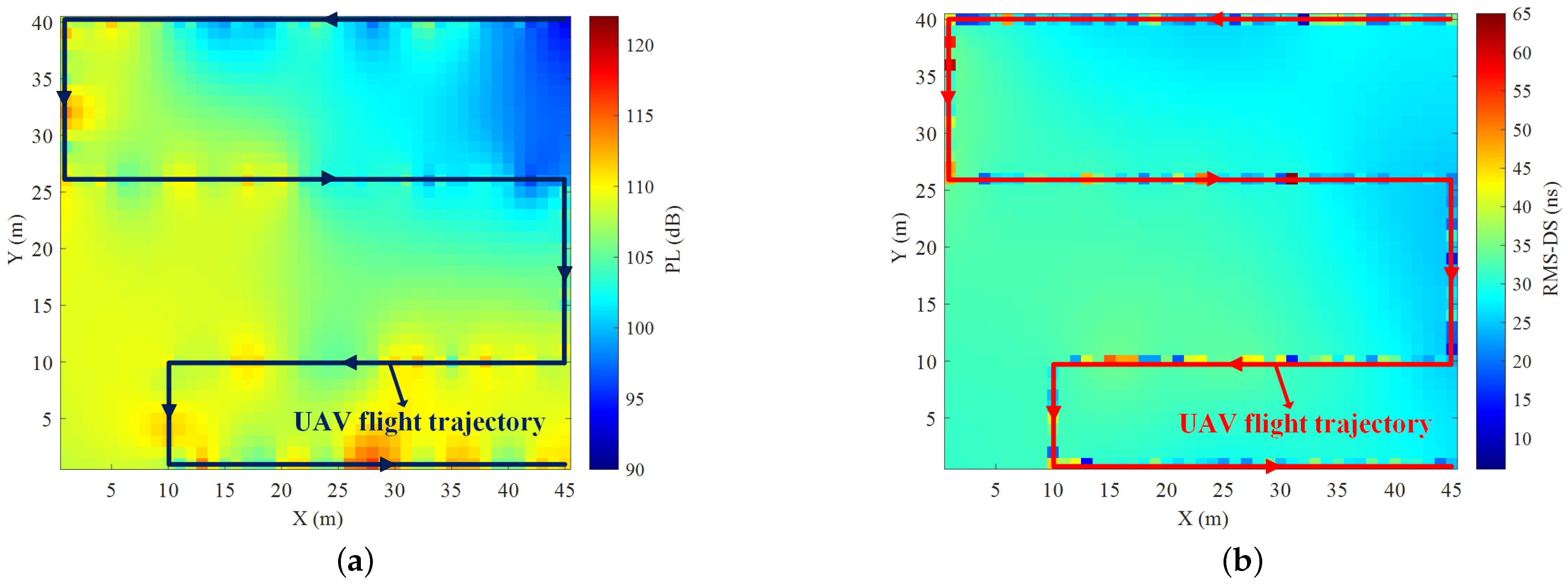
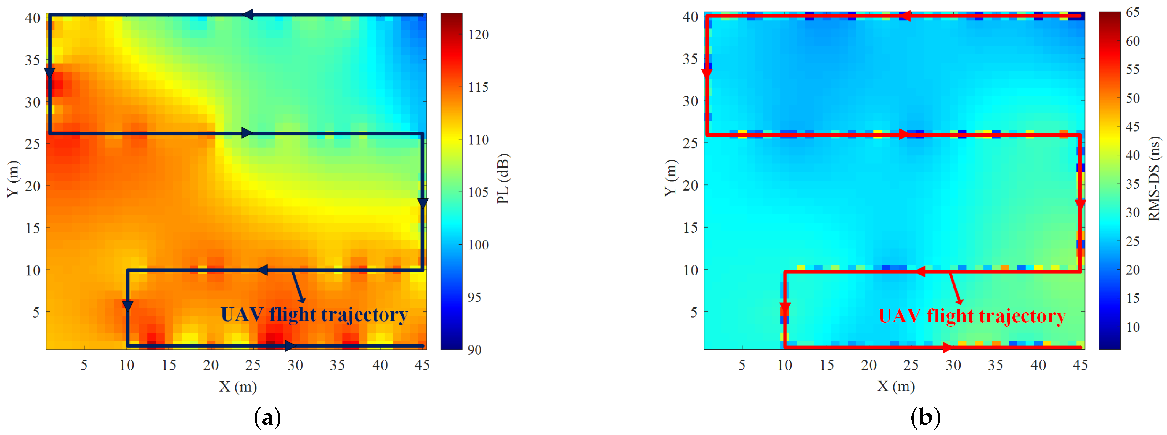
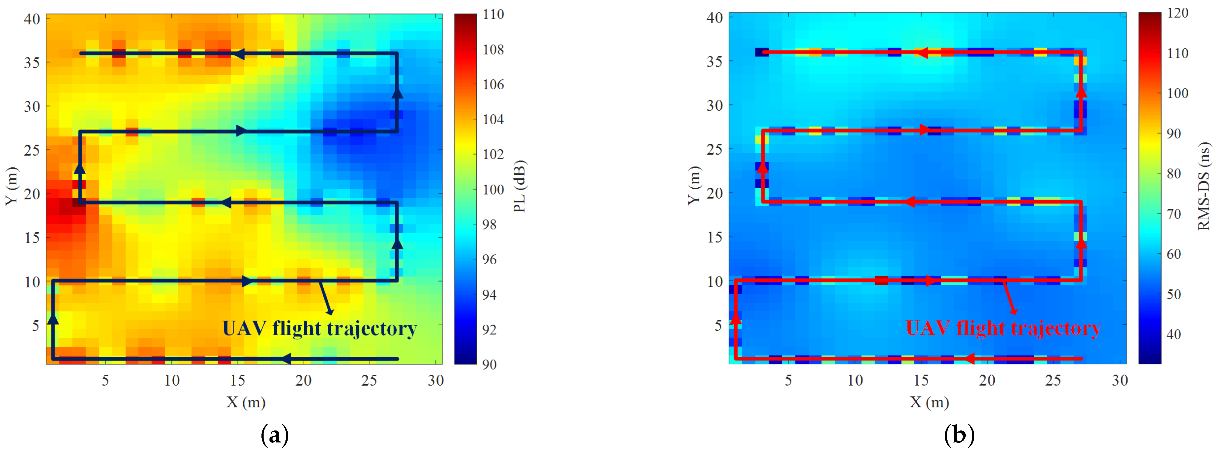
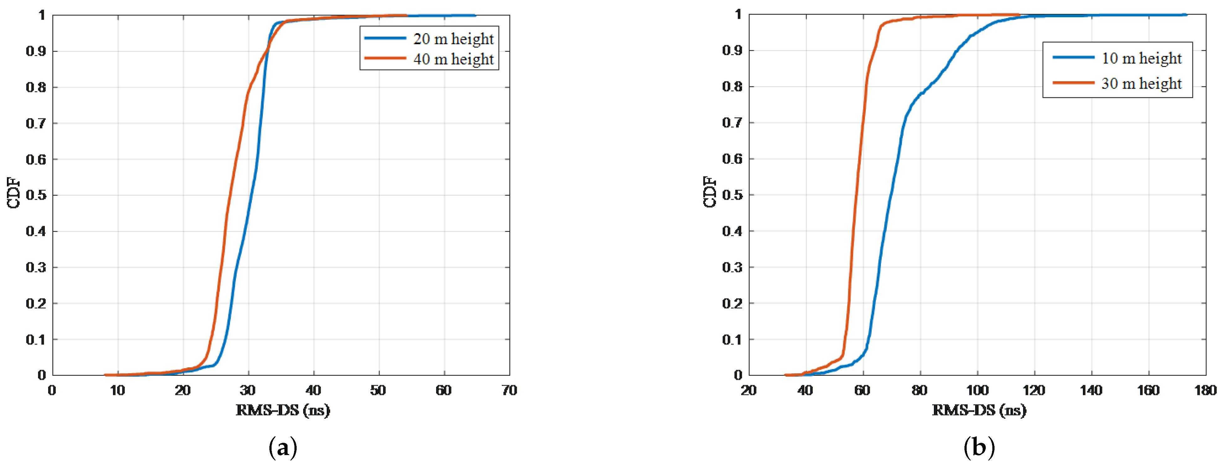
4.2. CKM Construction and Analysis

In the CKM measurement campaigns, we select the ZC sequence as the sounding sequence with N ZC = 1024 , the carrier frequency and sampling rate are 3.6 GHz and 61.44 MHz, the transmission power of the FPGA signal processing module is −10 dBm, the gain of HPA is 32 dB at 3.6 GHz, and the gain of the transceiver antenna is 3 dBi. Before the measurement campaigns begin, we first measure the loss of the cables at 5 dB, and at the same time, we connect the TX and RX back to back to eliminate the system response and improve the accuracy of the measurement. The GPS module of the TX and RX uses the PPS signal to trigger signal transmission and reception at the same time. Further, the UAV transmitting unit uses the GPS module to obtain the GPS time and location of each transmission sequence in real time, and the ground receiving unit uses the GPS module to obtain the GPS time of each received signal in real time. The UAV transmitting unit transmits the ZC sequence with a length of 1024 circularly, and the ground receiving unit extracts the CIR after the sliding correlation operation between the received signal and the local ZC sequence. The measurement interval of each CIR timeslot is about 16.67 μs. In order to improve the accuracy of the measurement, we set the UAV to fly at a constant speed of 1 m/s and trigger a transmission every 1 s, while the ground receiving unit also triggers a reception every 1 s. Each reception continuously stores 64 CIR slots and averages them.
Based on Section 3.2, effective multipaths in CIR are extracted and multiple channel knowledge is calculated. Meanwhile, multiple channel knowledge is completed based on the Kriging interpolation approach in Section 3.3, and the entire CKMs of PL and RMS-DS at the heights of 20 m and 40 m are constructed respectively in the campus scenario. Figure 7a,b and Figure 8a,b show the CKMs of PL and RMS-DS at heights of 20 m and 40 m in the campus scenario, respectively.
As can be seen from Figure 7 and Figure 8, the CKMs intuitively show the channel characteristics of PL and RMS-DS at the heights of 20 m and 40 m in the campus scenario. PL decreases with the increase in distance from the RX, while PL decreases with the increase in height. The CKMs of PL intuitively show the PL variation trend under this scenario. Similarly, Figure 9a,b and Figure 10a,b show the CKMs of PL and RMS-DS at heights of 10 m and 30 m in the farmland scenario, respectively. It can be seen that the CKMs also intuitively show the channel characteristics of different heights in the farmland scenario.
We plot the cumulative distribution function (CDF) diagrams of RMS-DS at different heights in the campus and farmland scenarios based on the entire CKMs after completion, as shown in Figure 11a,b. We observe that, in the campus scenario, RMS-DS is concentrated in 24–30 ns and 26–34 ns at heights of 20 m and 40 m, respectively. With the increase in height, the power of the line of sight path decreases, but the number of reflection paths decreases significantly, resulting in the decrease in the RMS-DS. In the farmland scenario, RMS-DS is concentrated in 45–60 ns and 65–75 ns at the heights of 10 m and 30 m, respectively. Similarly, with the increase in height, RMS-DS also decreases.
Due to the inevitable map errors in the process of actual measurement, some measurement points have large errors. However, in order to further verify the accuracy of the CKM construction scheme in this paper, we use 80% of the raw data as a test set to complete the entire CKMs. At the same time, 20% of the raw data is used as the verification set, and the RMSE of the raw data and the completed data is calculated to quantitatively analyze the accuracy of the CKM construction, where the RMSE can be expressed as
RMSE ( dB ) = 10 log 10 I ^ I true 2 I true 2
where I ^ is the completed data of channel knowledge in this paper, I true is the raw data of the channel knowledge, · 2 is 2-norm. According to the calculation results of formula (25), Figure 12 shows the RMSE for CKMs at different heights in two typical scenarios. The RMSE for the CKMs of PL and RMS-DS constructed at 20 m height in the campus scenario is −17.54 dB and −5.87 dB, respectively. Similarly, the RMSE for the CKMs of PL and RMS-DS constructed at 40 m height in the campus scenario are −16.68 dB and −4.52 dB, respectively. Then, the RMSE for the CKMs of the PL and RMS-DS constructed at 10 m height in the farmland scenario are −16.34 dB and −5.42 dB, respectively, and the RMSE for the CKMs of PL and RMS-DS constructed at 30 m height in the farmland scenario is −16.72 dB and −6.54 dB; these RMSE values show that the predicted value of the proposed CKM construction scheme is in good agreement with the measurement data, which indicates the proposed scheme can accurately construct the CKM at different heights.

5. Conclusions

In this paper, a comprehensive CKM construction scheme based on the UAV-assisted channel measurement system for real-world scenarios was presented, which involves channel knowledge extraction, mapping, and completion. Firstly, an adaptive dynamic noise threshold was generated based on the CFAR approach to extract effective multiple channel knowledge. Secondly, the channel knowledge at sparse locations was mapped to the elements in the CKM matrix. Finally, the 3D Kriging interpolation approach was used to complete the sparse CKM matrix. Meanwhile, a UAV-assisted channel measurement system was developed. We have conducted the measurement campaigns in two typical scenarios, i.e., campus and farmland and constructed the CKMs. Finally, the RMSE was used to verify the effectiveness and accuracy of the presented construction scheme and the UAV-assisted measurement system. In the future, we will use multi-UAVs for collaborative measurement to further improve efficiency and construct a wider-range CKM.

Author Contributions

Conceptualization, Y.Q. and Q.Z.; funding acquisition, X.C. and Q.Z.; investigation, K.M. and X.Y.; methodology, Y.Q. and K.M.; software, Y.Q. and X.Y.; data acquisition, X.Y. and H.L.; supervision, X.C., Y.H., and Q.Z.; validation, F.A.; writing—original draft, Y.Q. and Q.Z. All authors have read and agreed to the published version of the manuscript.

Funding

This work was supported in part by the National Natural Science Foundation of China under No. 62271250 and No. U23B2005, in part by Natural Science Foundation of Jiangsu Province, No. BK20211182, and in part by the Key Technologies R&D Program of Jiangsu (Prospective and Key Technologies for Industry) under No. BE2022067, and BE2022067-3, BE2022067-1.

Data Availability Statement

The datasets collected and generated in this study are available upon request to the corresponding author.

Conflicts of Interest

The authors declare no conflicts of interest.

References

  1. Mozaffari, M.; Saad, W.; Bennis, M.; Nam, Y.-H.; Debbah, M. A Tutorial on UAVs for Wireless Networks: Applications, Challenges, and Open Problems. IEEE Commun. Surveys Tuts. 2019, 21, 2334–2360. [Google Scholar] [CrossRef]
  2. Huang, Y.; Cui, H.; Hou, Y.; Hao, C.; Wang, W.; Zhu, Q.; Li, J.; Wu, Q.; Wang, J. Space-Based Electromagnetic Spectrum Sensing and Situation Awareness. Space Sci Technol. 2024, 4, 0109. [Google Scholar] [CrossRef]
  3. Xiao, Z.; Dong, H.; Bai, L.; Wu, D.O.; Xia, X.-G. Unmanned Aerial Vehicle Base Station (UAV-BS) Deployment With Millimeter-Wave Beamforming. IEEE Internet Things J. 2020, 21, 1336–1349. [Google Scholar] [CrossRef]
  4. Shi, M.; Yang, K.; Niyato, D.; Yuan, H.; Zhou, H.; Xu, Z. The Meta Distribution of SINR in UAV-Assisted Cellular Networks. IEEE Trans. Commun. 2023, 71, 1193–1206. [Google Scholar] [CrossRef]
  5. Zeng, Y.; Wu, Q.; Zhang, R. Accessing From the Sky: A Tutorial on UAV Communications for 5G and Beyond. Proc. IEEE 2019, 107, 2327–2375. [Google Scholar] [CrossRef]
  6. Na, Z.; Liu, Y.; Shi, J.; Liu, C.; Gao, Z. UAV-Supported Clustered NOMA for 6G-Enabled Internet of Things: Trajectory Planning and Resource Allocation. IEEE Internet Things J. 2021, 8, 15041–15048. [Google Scholar] [CrossRef]
  7. Hua, B.; Ni, H.; Zhu, Q.; Wang, C.-X.; Zhou, T.; Mao, K.; Bao, J.; Zhang, X. Channel Modeling for UAV-to-Ground Communications with Posture Variation and Fuselage Scattering Effect. IEEE Trans. Commun. 2023, 71, 3103–3116. [Google Scholar] [CrossRef]
  8. Pan, J.; Ye, N.; Yu, H.; Hong, T.; Al-Rubaye, S.; Mumtaz, S.; Al-Dulaimi, A.; Chih-Lin, I. AI-Driven Blind Signature Classification for IoT Connectivity: A Deep Learning Approach. IEEE Trans. Wireless Commun. 2022, 21, 6033–6047. [Google Scholar] [CrossRef]
  9. Ding, X.; Zhou, K.; Li, G.; Yang, K.; Gao, X.; Yuan, J.; An, J. Customized Joint Blind Frame Synchronization and Decoding Methods for Analog LDPC Decoder. IEEE Trans. Commun. 2024, 72, 756–770. [Google Scholar] [CrossRef]
  10. Lyu, Y.; Wang, W.; Sun, Y.; Yue, H.; Chai, J. Low-Altitude UAV Air-to-Ground Multilink Channel Modeling and Analysis at 2.4 and 5.9 GHz. IEEE Antennas Wireless Propag. Lett. 2023, 22, 2135–2139. [Google Scholar] [CrossRef]
  11. Lyu, Y.; Wang, W.; Rashdan, I. Measurement-based Fading Characteristics Analysis and Modeling of UAV to Vehicles Channel. Veh. Commun. 2024, 45, 100707. [Google Scholar] [CrossRef]
  12. Fuschini, F.; Barbiroli, M.; Vitucci, E.M.; Semkin, V.; Oestges, C.; Strano, B.; Degli-Esposti, V. An UAV-Based Experimental Setup for Propagation Characterization in Urban Environment. IEEE Trans. Instrum. Meas. 2021, 70, 1–11. [Google Scholar] [CrossRef]
  13. Zhang, H.; Zhang, Y.; Cosmas, J.; Jawad, N.; Li, W.; Muller, R.; Jiang, T. mmWave Indoor Channel Measurement Campaign for 5G New Radio Indoor Broadcasting. IEEE Trans. Broadcast. 2022, 68, 331–344. [Google Scholar] [CrossRef]
  14. Quimby, J.T.; Williams, D.F.; Remley, K.A.; Ribeiro, D.; Sun, R.; Senic, J. Millimeter-Wave Channel-Sounder Performance Verification Using Vector Network Analyzer in a Controlled RF Channel. IEEE Trans. Antennas Propag. 2021, 69, 7867–7875. [Google Scholar] [CrossRef] [PubMed]
  15. Mbugua, A.W.; Fan, W.; Olesen, K.; Cai, X.; Pedersen, G.F. Phase-Compensated Optical Fiber-Based Ultrawideband Channel Sounder. IEEE Trans. Microw. Theory Tech. 2019, 68, 636–647. [Google Scholar] [CrossRef]
  16. Lyu, Y.; Kyösti, P.; Fan, W. Sub-Terahertz Channel Sounder: Review and Future Challenges. China Commun. 2023, 20, 26–48. [Google Scholar] [CrossRef]
  17. Mao, K.; Zhu, Q.; Qiu, Y.; Liu, X.; Song, M.; Fan, W.; Kokkeler, A.B.J.; Miao, Y. A UAV-Aided Real-Time Channel Sounder for Highly Dynamic Non-Stationary A2G Scenarios. IEEE Trans. Instrum. Meas. 2023, 72, 1–15. [Google Scholar]
  18. Zeng, Y.; Xu, X. Toward Environment-Aware 6G Communications via Channel Knowledge Map. IEEE Wireless Commun. 2021, 28, 84–91. [Google Scholar] [CrossRef]
  19. Xia, X.; Wang, Y.; Xu, K.; Xu, Y. Toward Digitalizing the Wireless Environment: A Unified A2G Information and Energy Delivery Framework Based on Binary Channel Feature Map. IEEE Trans. Wireless Commun. 2022, 21, 6448–6463. [Google Scholar] [CrossRef]
  20. Zhao, Y.; Zhu, Q.; Lin, Z.; Guo, L.; Wu, Q.; Wang, J.; Zhong, W. Temporal Prediction for Spectrum Environment Maps with Moving Radiation Sources. IET Commun. 2022, 17, 539–548. [Google Scholar] [CrossRef]
  21. Ruan, T.; Huang, Y.; Zhu, Q.; Hao, C.; Wu, Q. Multi-Stage RF Emitter Search and Geolocation With UAV: A Cognitive Learning-Based Method. IEEE Trans. Veh. Technol. 2023, 72, 6349–6362. [Google Scholar] [CrossRef]
  22. Zhang, S.; Zhang, R. Radio Map-Based 3D Path Planning for Cellular-Connected UAV. IEEE Trans. Wireless Commun. 2021, 20, 1975–1989. [Google Scholar] [CrossRef]
  23. Wu, D.; Zeng, Y.; Jin, S.; Zhang, R. Environment-Aware Hybrid Beamforming by Leveraging Channel Knowledge Map. IEEE Trans. Wireless Commun. 2023, 23, 4990–5005. [Google Scholar] [CrossRef]
  24. Ding, D.; Wu, D.; Zeng, Y.; Jin, S.; Zhang, R. Environment-Aware Beam Selection for IRS-Aided Communication with Channel Knowledge Map. In Proceedings of the 2021 IEEE Globecom Workshops (GC Wkshps), Madrid, Spain, 7–11 December 2021; pp. 1–6. [Google Scholar]
  25. Li, H.; Li, P.; Cheng, G.; Xu, J.; Chen, J.; Zeng, Y. Channel Knowledge Map (CKM)-Assisted Multi-UAV Wireless Network: CKM Construction and UAV Placement. J. Commun. Inf. Netw. 2023, 8, 256–270. [Google Scholar] [CrossRef]
  26. Li, H.; Li, P.; Xu, J.; Chen, J.; Zeng, Y. Derivative-Free Placement Optimization for Multi-UAV Wireless Networks with Channel Knowledge Map. In Proceedings of the 2022 IEEE International Conference on Communications Workshops (ICC Workshops), Seoul, Republic of Korea, 16–20 May 2022; pp. 1029–1034. [Google Scholar]
  27. Claussen. Efficient modelling of channel maps with correlated shadow fading in mobile radio systems. In Proceedings of the 2005 IEEE 16th International Symposium on Personal, Indoor and Mobile Radio Communications, Berlin, Germany, 11–14 September 2005; pp. 512–516. [Google Scholar]
  28. Dall’Anese, E.; Kim, S.-J.; Giannakis, G.B. Channel Gain Map Tracking via Distributed Kriging. IEEE Trans. Veh. Technol. 2011, 60, 1205–1211. [Google Scholar] [CrossRef]
  29. Mao, D.; Shao, W.; Qian, Z.; Xue, H.; Lu, X.; Wu, H. Constructing Accurate Radio Environment Maps with Kriging Interpolation in Cognitive Radio Networks. In Proceedings of the 2018 Cross Strait Quad-Regional Radio Science and Wireless Technology Conference (CSQRWC), Xuzhou, China, 21–24 July 2018; pp. 1–3. [Google Scholar]
  30. Chen, J.; Yatnalli, U.; Gesbert, D. Learning Radio Maps for UAV-Aided Wireless Networks: A Segmented Regression Approach. In Proceedings of the 2017 IEEE International Conference on Communications (ICC), Paris, France, 21–25 May 2017; pp. 1–6. [Google Scholar]
  31. Zhu, Q.; Zhao, Y.; Huang, Y.; Lin, Z.; Wang, L.H.; Bai, Y.; Lan, T.; Zhou, F.; Wu, Q. An UAV-based 3D Spectrum Real-time Mapping System. In Proceedings of the IEEE INFOCOM 2022—IEEE Conference on Computer Communications Workshops (INFOCOM WKSHPS), New York, NY, USA, 2–5 May 2022; pp. 1–2. [Google Scholar]
  32. Wang, J.; Zhu, Q.; Lin, Z.; Wu, Q.; Huang, Y.; Cai, X.; Zhong, W.; Zhao, Y. Sparse Bayesian Learning-Based 3D Radio Environment Map Construction—Sampling Optimization, Scenario-Dependent Dictionary Construction and Sparse Recovery. IEEE Trans. Cogn. Commun. Netw. 2024, 10, 80–93. [Google Scholar] [CrossRef]
  33. Qiu, Y.; Chen, X.; Mao, K.; Ye, X.; Zhao, Y.; Ge, Y.; Zhong, W.; Zhu, Q. Channel Knowledge Extraction and Completion Methods for 3D CKM Construction. In Proceedings of the International Conference in Communications, Signal Processing, and Systems, Singapore, 12–15 July 2023; pp. 275–283. [Google Scholar]
  34. Zhu, Q.; Mao, K.; Song, M.; Chen, X.; Hua, B.; Zhong, W.; Ye, X. Map-Based Channel Modeling and Generation for U2V mmWave Communication. IEEE Trans. Veh. Technol. 2022, 71, 8004–8015. [Google Scholar] [CrossRef]
  35. Mao, K.; Zhu, Q.; Song, M.; Li, H.; Ning, B.; Pedersen, G.F.; Fan, W. Machine-Learning-Based 3D Channel modeling for U2V mmWave communications. IEEE Internet Things J. 2022, 9, 17592–17607. [Google Scholar] [CrossRef]
  36. Jiang, H.; Xiong, B.; Zhang, H.; Basar, E. Hybrid Far- and Near-Field Modeling for Reconfigurable Intelligent Surface Assisted V2V Channels: A Sub-Array Partition Based Approach. IEEE Trans. Wireless Commun. (Early Access) 2023, 22, 8290–8303. [Google Scholar] [CrossRef]
  37. Zhang, D.; Ai, B.; Fei, D.; Chen, Z. Comparison of Different Sounding Waveforms for a Wideband Correlation Channel Sounder. In Proceedings of the 5th International Conference on Electrical Engineering and Information Technologies for Rail Transportation (EITRT), Qingdao, China, 22–24 October 2021; pp. 119–126. [Google Scholar]
  38. An, H.; Guan, K.; Li, W.; Zhang, J.; He, D.; Zhu, F.; Chen, L. Measurement and Ray-Tracing for UAV Air-to-Air Channel Modeling. In Proceedings of the 2022 IEEE 5th International Conference on Electronic Information and Communication Technology (ICEICT), Hefei, China, 21–23 August 2022; pp. 1–6. [Google Scholar]
  39. Gomez-Ponce, J.; Choi, T.; Abbasi, N.A.; Adame, A.; Alvarado, A.; Bullard, C.; Shen, R.; Daneshgaran, F.; Dhillon, H.S.; Molisch, A.F. Air-to-Ground Directional Channel Sounder With Drone and 64-antenna Dual-polarized Cylindrical Array. In Proceedings of the 2021 IEEE International Conference on Communications Workshops (ICC Workshops), Montreal, QC, Canada, 14–23 June 2021; pp. 1–6. [Google Scholar]
  40. Khawaja, W.; Ozdemir, O.; Erden, F.; Guvenc, I.; Matolak, D.W. Ultra-Wideband Air-to-Ground Propagation Channel Characterization in an Open Area. IEEE Trans. Aerosp. Electron. Syst. 2020, 56, 4533–4555. [Google Scholar] [CrossRef]
  41. Cui, Z.; Briso, C.; Guan, K.; Matolak, D.W.; Calvo-Ramírez, C.; Ai, B.; Zhong, Z. Low-Altitude UAV Air-Ground Propagation Channel Measurement and Analysis in a Suburban Environment at 3.9 GHz. IET Microw. Antennas Propag. 2019, 13, 1503–1508. [Google Scholar] [CrossRef]
  42. Santoso, T.B.; Huda, M.; Mahmudah, H. Performance Evaluation of CFAR Detector for Delay Spread Analysis of Underwater Acoustic Channel. In Proceedings of the 2015 International Electronics Symposium (IES), Surabaya, Indonesia, 29–30 September 2015; pp. 173–177. [Google Scholar]
  43. Ovchinnikov, V.V.; Ryabova, N.V.; Elsukov, A.A. Adaptive HF Signal Detection Algorithm CFAR and Its Verification By Means of SDR Based Digital Ionosonde with USRP Platform. In Proceedings of the 2018 Systems of Signal Synchronization, Generating and Processing in Telecommunications (SYNCHROINFO), Minsk, Belarus, 4–5 July 2018; pp. 1–5. [Google Scholar]
  44. Ferreira, S.; Gonsioroski, L.; Santos, A.d.; Batista, J.; Matos, L.; Castellanos, P.G.; Silva, R.M.L.; Oliveira, C.H.R. Power Delay Profile Filtering Technique Using Artificial Neural Networks. In Proceedings of the 2020 IEEE Latin-American Conference on Communications (LATINCOM), Santo Domingo, Dominican Republic, 18–20 November 2020; pp. 1–6. [Google Scholar]
Figure 1. 3D grid model of CKM.
Drones 08 00191 g001
Figure 2. Overview of the UAV-assisted CKM construction scheme.
Drones 08 00191 g002
Figure 3. The adaptive noise threshold calculation.
Drones 08 00191 g003
Figure 4. Comparison of constant and adaptive noise threshold methods.
Drones 08 00191 g004
Figure 5. UAV-assisted channel measurement system.
Drones 08 00191 g005
Figure 6. CKM measurement campaigns in (a) campus and (b) farmland scenarios.
Drones 08 00191 g006
Figure 7. The CKMs of (a) PL and (b) RMS-DS at height of 20 m in campus scenario.
Drones 08 00191 g007
Figure 8. The CKMs of (a) PL and (b) RMS-DS at height of 40 m in campus scenario.
Drones 08 00191 g008
Figure 9. The CKMs of (a) PL and (b) RMS-DS at height of 10 m in farmland scenario.
Drones 08 00191 g009
Figure 10. The CKMs of (a) PL and (b) RMS-DS at height of 30 m in farmland scenario.
Drones 08 00191 g010
Figure 11. The CDF of RMS-DS at different heights in (a) campus and (b) farmland scenarios.
Drones 08 00191 g011
Figure 12. The RMSE of CKMs at different heights.
Drones 08 00191 g012
Table 1. Summary of hardware components.
TypesFeatures
TX/RX antennaFrequency range: 3.2 GHz–3.9 GHz
Gain: 3 dBi
FPGA signal
processing module
Frequency range: 500 MHz–6 GHz
Bandwidth: 61.44 MHz
RX SDR moduleFrequency range: 1 GHz–4 GHz
Bandwidth: 100 MHz
Disclaimer/Publisher’s Note: The statements, opinions and data contained in all publications are solely those of the individual author(s) and contributor(s) and not of MDPI and/or the editor(s). MDPI and/or the editor(s) disclaim responsibility for any injury to people or property resulting from any ideas, methods, instructions or products referred to in the content.

