Article

UAV-Mounted RIS-Aided Mobile Edge Computing System: A DDQN-Based Optimization Approach

1
School of Space Information, Space Engineering University, Beijing 101416, China
2
China Unicom Research Institute, Beijing 100176, China
3
Key Laboratory of Intelligent Space TT&C and Operation, Ministry of Education, Beijing 101416, China
4
Department of Electronic and Optical Engineering, Space Engineering University, Beijing 101416, China
*
Author to whom correspondence should be addressed.
Drones 2024, 8(5), 184; https://doi.org/10.3390/drones8050184
Submission received: 19 April 2024 / Revised: 4 May 2024 / Accepted: 7 May 2024 / Published: 7 May 2024
(This article belongs to the Special Issue Mobile Fog and Edge Computing in Drone Swarms)

Abstract

:
Unmanned aerial vehicles (UAVs) and reconfigurable intelligent surfaces (RISs) are increasingly employed in mobile edge computing (MEC) systems to flexibly modify the signal transmission environment. This is achieved through the active manipulation of the wireless channel facilitated by the mobile deployment of UAVs and the intelligent reflection of signals by RISs. However, these technologies are subject to inherent limitations such as the restricted range of UAVs and limited RIS coverage, which hinder their broader application. The integration of UAVs and RISs into UAV–RIS schemes presents a promising approach to surmounting these limitations by leveraging the strengths of both technologies. Motivated by the above observations, we contemplate a novel UAV–RIS-aided MEC system, wherein UAV–RIS plays a pivotal role in facilitating communication between terrestrial vehicle users and MEC servers. To address this challenging non-convex problem, we propose an energy-constrained approach to maximize the system’s energy efficiency based on a double-deep Q-network (DDQN), which is employed to realize joint control of the UAVs, passive beamforming, and resource allocation for MEC. Numerical results demonstrate that the proposed optimization scheme significantly enhances the system efficiency of the UAV–RIS-aided time division multiple access (TDMA) network.

1. Introduction

In light of widespread mobile vehicle user adoption and the exponential growth of Internet of Things (IoT) network traffic, mobile edge computing (MEC) has emerged as a promising paradigm [1]. This is due to the fact that, on the one hand, MEC enables the placement of computational resources and storage functions at the network edge to bring data processing closer to the terminal, which iscrucial for performing computationally intensive and latency-sensitive tasks [2]; on the other hand, as IoT devices proliferate and become more prevalent, a centralized approach to data processing is no longer sufficient. MEC offers a viable solution for next-generation Internet of Vehicle (IoV) deployments, facilitating better communication and collaboration among various devices. However, the effectiveness of MEC systems is limited by challenges in the offloading process. One major challenge is potential congestion of the direct offloading link, which often results in sub-optimal performance, compelling users to process tasks locally in order to meet strict latency requirements. This situation is particularly unfavorable for mobile users with limited resources. To overcome these limitations, various research efforts have focused on improving channel quality in MEC systems. By utilizing UAVs as mobile platforms for MEC servers, it becomes possible to actively manage the wireless channel and optimize signal transmission conditions. The dynamic mobility of UAVs allows for strategic positioning, thereby enhancing overall system performance [3]. This integration of UAVs and MEC offers an efficient means of extending traditional MEC system capabilities.

1.1. Related Work and Motivation

The UAV-enabled MEC system serves as a flexible technological approach that can effectively ensure full utilization of computational resources and significantly reduce capital costs. Through the UAV-enabled MEC system, the UAV offloads time processing-sensitive or computationally intensive tasks to the server in order to maximize the savings of UAV battery resources and computational resources. Driven by the advantages of UAV-enabled MEC, there have been a large number of contributions studying UAV-enabled MEC systems, and many effective algorithms have been proposed based on different optimization objectives. For instance, the authors of [4] investigated the energy efficiency (EE) maximization problem concerning edge computing through optimization of resource allocation and UAV trajectory design. Similar to the above content, the authors of [5] designed a cooperative strategy for deploying multiple ground servers and a UAV mobile server to achieve highly reliable edge computing services.
On the other hand, reconfigurable intelligent surfaces (RISs) consisting of a passive reflective planar device have been recognized as a novel paradigm with the ability to alter the signal propagation environment through low-cost implementations. An RIS manipulates incoming signals [6], thereby altering the channel conditions of the UAV-assisted MEC system and significantly improving spectrum utilization efficiency. RISs have been proven by numerous research results to be potentially advantageous in improving channel conditions and enhancing energy transfer in multicellular networks, which can significantly improve the performance of UAV-enabled MEC systems.
Therefore, the integration of RIS into UAV-enabled MEC systems is considered a mutually beneficial strategy. According to a report in [7], the presence of RISs can eliminate up to 20% of the computational delay, demonstrating their potential impact on the performance of UAV-enabled MEC systems. However, both UAVs and RISs face inherent limitations, such as the limited endurance of UAVs and the fact that an RIS can only provide reflective gain at half the range in space. To address these challenges, the concept of integrating RISs onto UAVs to support ground edge computing communication, referred to as UAV-mounted RIS schemes (UAV–RIS) [8], is emerging as a promising approach. The UAV–RIS architecture is a significant improvement over traditional UAV-enabled server schemes, where information is reflected through RISs to a terrestrial MEC server for computation without the need to change routing or rebuild the system. In addition, RIS units are typically much lighter than MEC servers, reducing the onboard energy consumption of the UAV. Moreover, an RIS is only a two-dimensional plane, and is typically much lighter than an MEC server [9], resulting in reduced onboard energy consumption for UAVs. The authors of [10] mentioned the use of rate-splitting multiple-access (RSMA) technology to provide a more robust offloading strategy in RIS-assisted MEC systems. In [11], the authors investigated the optimization of system energy efficiency under an RIS–UAV-enabled MEC system using successive convex approximation (SCA) and the Dinkelbach method. The authors of [12] considered a UAV-enabled MEC system assisted by RIS with the optimization objective of minimizing UAV energy consumption under a multitude of influencing factors, including transmit power, RIS phase shift, resource allocation strategy, and more. In summary, in scenarios involving RIS-assisted MEC, RISs deployed on building facades prove effective only for users within the frontal spatial sector. In contrast, when mounted on aerial platforms such as UAVs, RISs exhibit superior omnidirectional beamforming capabilities for ground users, providing more comprehensive and panoramic coverage [13].
From the above analysis, it is obvious that the integration of RIS-carrying UAVs into the MEC system represents an indispensable and critical route to improving the overall computational efficiency. However, because of the superimposed effects of multiple phase multiplications of the RIS involved, this is a high-dimensional problem with multiple optimization objectives and represents a challenging task for conventional iterative algorithms. Thanks to the great popularity of artificial intelligence (AI) in many fields, the introduction of this technique into wireless communications has become a recent research trend. Among these, deep reinforcement learning (DRL) has emerged as a particularly powerful tool for enhancing the performance of wireless networks in dynamic environments. DRL can combine neural networks with powerful function-fitting capabilities and reinforcement learning to optimize large-scale network operations without the need for massive amounts of high-quality data for pretraining. Instead, the environment is modeled and rewards from the environment are used as feedback to train the system. The authors of [14] considered an optimization strategy for maximizing the long-term effectiveness of vehicular edge computing networks using Q-learning and DRL frameworks. In [15], the authors utilized an end-to-end DRL framework for offloading and allocating computational resources by selecting the optimal edge servers.
Although various advanced techniques such as RISs, UAVs, and DRL have been successfully applied in MEC systems, to the best of the authors’ knowledge there is still a gap in the research of performance optimization strategies for MEC systems after integrating all the above techniques together. In particular, for the extended DRL framework involving computational offloading strategies, optimization of RIS phase-shift parameters is the focus of our concern, and drives the research of this paper.

1.2. Contributions and Novelty

Building upon the comprehensive analysis provided above, we propose the integration of an MEC system employing UAV-carried RISs. In the envisioned system, each UAV is equipped with an RIS to serve ground users and MEC servers. Our primary objective is to maximize computational offloading efficiency while considering the energy consumed by the UAVs. To achieve this, we leverage the Double Deep Q-Network (DDQN) algorithm, which offers several advantages for learning multiple actions. We introduce a DDQN-based scheme aimed at maximizing computational offloading efficiency under various constraints, simultaneously addressing trajectory optimization and phase shift problems. The contributions of this setup include:
  • First, in complex environments such as densely populated urban areas hosting large-scale events, the line-of-sight link between terrestrial vehicle users (VUs) and the MEC server may be weakened by obstacles. To overcome this challenge, we propose the strategy of deploying RIS-carrying UAVs to assist users in offloading tasks. By reflecting VU signals through the UAV–RIS system, they are able reach the ground MEC servers effectively.
  • Second, this computational offloading policy optimization problem can be categorized as a mixed-integer nonlinear fractional programming problem. To tackle this, we develop the DDQN-empowered algorithm, which aims to achieve the goal of maximizing energy efficiency. This algorithm offers low computational complexity while allowing for easy scalability across various system configurations.
  • Finally, the numerical results obtained from our experiments demonstrate significant improvements in energy efficiency within the MEC system compared to other benchmark schemes. Furthermore, our proposed algorithm makes notable trade-offs in trajectory optimization, enhancing the overall performance of the system.
The rest of this paper is organized as follows. Section 2 describes the considered MEC system model and the formulation of the optimization problem in detail. In Section 3, we focus on the computational efficiency problem of the DRL-based algorithm. In Section 4, we present simulation results demonstrating the performance advantages of the proposed DDQN framework. Finally, our conclusions are summarized in Section 5. For more concise representation, symbols for several key system parameters are defined in Table 1.

2. System Model Description

The diagram in Figure 1 depicts the conceptual model of the UAV–RIS-aided MEC system, incorporating several key components. Specifically, the system consists of K terrestrial vehicle users (VUs), an MEC ground server, and a UAV equipped with an RIS. This configuration enables the seamless integration of aerial and ground infrastructure to support efficient and dynamic mobile edge computing operations. In this configuration, the UAV–RIS plays a crucial role in facilitating edge computing services from the VUs to the MEC terrestrial servers. This investigation occurs over a designated time period T, which (without loss of generality) is segmented into N discrete time slots for the sake of analysis, allowing for the development of policies and strategies that are adaptive to changing environmental conditions and user demands.
We can make the assumption that all communication nodes are represented within a 3D Cartesian coordinate system, providing a standardized and consistent framework for spatial representation and analysis [16]. In particular, the k-th VU and the MEC server can be expressed as L k = x k , y k and L M = x M , y M , respectively. In addition, to maintain dynamic balance during RIS-assisted communication, it can be assumed that the UAV carrying the RIS only performs the reflection task at the same altitude H R [17]. Therefore, the motion trajectory of the UAV–RIS within time span T at the n-th time slot can be expressed as q n = x n , y n , H R , n N . At the same time, we define the flight process as follows:
v n = q n q n 1 Δ t , v max v n , n N ,
a n = v n v n 1 Δ t , a max a n , n N ,
where Δ t denotes the length of each time slot, v max is the maximum flying speed, and a max is the maximum acceleration. Additionally, it is worth noting that the UAV should be connected to different fixed charging positions from both the starting and ending positions for stable power control.

2.1. Signal Transmission Model

Within the system model, we pragmatically consider that both the MEC ground server and the VU are outfitted with omnidirectional antennas to establish a common basis for signal propagation analysis. Meanwhile, the RIS is comprised of M = M x × M y reflecting elements, with M x representing the number of elements along the x-axis and M y denoting the number of elements along the y-axis, thereby forming a rectangular array plane. To describe the phase shift of the m-th element at the n-th time slot, we denote it as θ m n 0 , 2 π ,   m M = Δ 1 , , M , and Θ n = diag e j θ 1 n , e j θ 2 n , , e j θ M n , which can be understood as the diagonal phase shift matrix for the RIS at the n-th time slot. This configuration allows for precise control and manipulation of the phase shifts across the RIS elements, enabling adaptive signal reflection and optimization within the wireless environment.
In the scenario where the RIS-carrying UAV acts as an auxiliary communication service in the air, it is reasonable to assume that there is a strong LoS link between the UAV–RIS and the terrestrial VUs, including the link from the UAV–RIS to the MEC server. This assumption is based on the fact that the UAV is positioned at a higher altitude, providing a direct and unobstructed path for communication. As a result, it is justifiable to make the assumption that the channels from the VU to the UAV–RIS and from the UAV–RIS to the MEC server adhere to a quasi-static fast-fading LoS model. This model takes into account the rapid fluctuations in signal strength caused by factors such as small-scale fading and multipath propagation. By considering this, we can better analyze and optimize the performance of the communication system by taking into account the dynamic characteristics of the channel. The channel from the UAV–RIS to the MEC server, denoted as h s n C 1 × M , can be mathematically expressed as
h s n = L n a x m n a y m n ,
where the term L n = G 0 d α β n denotes the path loss component (with G 0 being the channel gain), d n = q n L M 2 + H R 2 is the distance between the MEC ground server and the UAV-RIS at the n-th time slot, and α β stands for the path loss exponent associated with the LoS transmission. It is worth noting that the path loss component plays a crucial role in determining the signal strength and the quality of the communication link in the system by taking into account the channel gain, the distance between various communication nodes, and the path loss characteristics due to LoS transmission:
a x m n = exp 0 , j 2 π λ R d cos ϕ m n sin φ m n , , j 2 π λ R M x 1 d cos ϕ m n sin φ m n T ,
a y m n = exp 0 , j 2 π λ R d sin ϕ m n sin φ m n , , j 2 π λ R M y 1 d sin ϕ m n sin φ m n T ,
where ϕ m n and φ m n are the azimuth and elevation angles of the m-th element of the RIS at the n-th time slot, and λ R is the carrier frequency. Moreover, the link between the k-th VU and the UAV–RIS can be denoted as h k n , which is modeled in a similar way as described above.
In our work, we consider the time-division multiple-access (TDMA) scheme for offloading the computing task. Put another way, it can be understood that only one user communicates with the MEC server at each time slot, and we assume that s k n is the content that the ground user needs to schedule at the n-th time slot. If the UAV carrying the RIS is required to provide reflection services at the k-th VU, the demand can be expressed as
k = 1 K s k n = 1 , s k n 0 , 1 , k , n .
As a result, the achievable rate for the k-th VU can be defined as
R k [ n ] = s k [ n ] B k log 2 1 + p k h s [ n ] H Θ [ n ] h k [ n ] 2 σ 2 ,
where B k denotes the bandwidth, p k is the transmit power for the k-th VU, and σ 2 means the variance in the obeying noise distribution. Here, the average achievable rate for the k-th VU throughout the entire computation duration T can be formulated as R k = 1 N n = 1 N R k [ n ] .

2.2. Computational Offloading Model

In order to leverage the finer granularity of task partitioning and computational resources, we have incorporated a strategy known as partial offloading into the system design. This methodology involves dividing computational tasks into adaptable segments, enabling a fraction of these tasks to be offloaded to the server for processing while retaining the remainder for local execution. By implementing partial offloading, the system gains increased flexibility in managing computational workloads and optimizing resource utilization. This approach allows for a more nuanced distribution of tasks between local processing and offloading to the server based on factors such as task complexity, latency requirements, and available network resources. This flexibility enables efficient task scheduling, with critical or latency-sensitive tasks offloaded for quicker processing and less time-sensitive tasks executed locally to minimize delays [18]. The aggregate offloaded tasks and locally computed tasks for the k-th VU across N time slots are denoted as c k o and c k l . If T k is assumed to be the maximum tolerable delay for the k-th VU, this can be expressed as
max c k l χ k f k l , c k o χ k f k o + c k o R k T k , k ,
where χ k denotes the number of central processing unit (CPU) cycles required to process a single bit of data from the k-th VU. In this context, f k l denotes the fixed CPU frequency for the k-th VU, while f k o represents the CPU frequency allocated for processing the k-th VU task at the MEC server. The foundation of this restriction rests on two core assumptions: first, initiation of edge computation for the k-th VU is contingent upon the completion of offloading all f k l bits; second, the system leverages dynamic voltage and frequency scaling (DVFS) techniques to dynamically allocate server resources. These sophisticated techniques empower real-time adjustments in CPU voltage and frequency, optimizing power consumption and performance in response to the prevailing workload conditions.

2.3. Energy Dissipation Model

The proposed UAV–RIS-aided MEC system model considers three key components that contribute to the total energy dissipation across all time slots T. These include the energy consumed during UAV flight, the energy required for user task offloading and local execution of computational tasks, and the energy consumption of the edge computing server. Thus, the energy consumption during the execution of the k-th VU edge computation can be accurately modeled as
E k l = T k p k + Υ l χ k c k l f k l 2 , k ,
where Υ l is the locally calculated conversion factor for the k-th VU. Furthermore, we define Υ o as the computed conversion factor for the MEC terrestrial server, which can provide more details about the energy utilization pattern of the MEC terrestrial server and help to target interventions. At this point, while the energy dissipation of the MEC ground server at the k-th VU in the prespecified mode can be expressed as
E k o = Υ o χ k c k o f k o 2 , k ,
the final component of the proposed energy consumption model is focused on the UAV’s energy consumption, which will account for the vast majority of the energy consumption and can be expressed as E u n . For this purpose, it is assumed that the proposed UAV is a rotary-wing UAV and that its energy consumption model takes into account the thrust-to-weight ratio, which is influenced by multiple factors such as acceleration and gravity during actual flight. In particular, the energy consumption model for the UAV comprehensively considers factors such as the weight of the UAV, its aerodynamic and mechanical efficiency, and the power required to maintain altitude and perform maneuvers. Specific details of this section can be found at [19]. Therefore, the energy dissipation model can be expressed as
E T = η n = 1 N E u n + k = 1 K E k l + E k o ,
where η denotes the weighting factor to strike a balance between these different components. This is because the energy consumption of the UAV carrying the RIS for flight is much higher compared to the computational losses and the energy consumption of the MEC ground server. However, both the local VU computation and the server’s energy consumption are important factors to consider.

2.4. Problem Formulation

In the proposed UAV–RIS-aided edge computing system, energy efficiency (EE) is defined as the ratio of the total number of bits of computational tasks to the system energy consumption after performing as many computational services as possible under energy constraints, which is provided by both local services and edge computing servers. Our main objective is jointly optimizing user scheduling s k n , the UAV trajectory Q = Δ q n , n N , and the RIS phase shifts to maximize the achievable rate in all required tasks. This optimization problem can be modeled as
P 0 : E E [ n ] = max Q , S , Φ k = 1 K c k o + c k l E T
s . t . C 1 : 0 θ m [ n ] < 2 π , n , m ,
C 2 : k = 1 K f k o F O ,
C 3 : I k c k o , k ,
C 4 : Equations   ( 1 )   and   ( 2 ) ,
C 5 : x min x n x max , n ,
C 6 : y min y n y max , n .
where (12b) represents the phase shift constraint associated with each reflection element, (12c) denotes the maximum tolerable CPU frequency of the MEC server, (12d) signifies the minimum offload task threshold for the k-th user, and (12e) and (12f) indicate the flight range of the UAV. The optimization problem described above presents a notable challenge due to its mixed-integer nature. This characteristic makes it difficult to find an optimal solution efficiently, as it requires exploring a complex and nonconvex search space. Moreover, the dynamic nature of the scenario, with both the UAV and the onboard RIS in motion, further complicates the situation, presenting a challenge for traditional optimization algorithms. In response to these challenges, our approach involves leveraging the DRL-enabled framework. Through the integration of DRL, the system gains the ability to learn from its environment and make informed decisions, enabling it to navigate and tackle the inherent complexities of the problem with adaptability and intelligence. This approach empowers the agent to dynamically adjust its strategies based on real-time feedback and environmental cues, leading to more effective and data-driven decision-making processes that enhance overall performance and efficiency [20]. This adaptive framework enables the agent to dynamically adapt to changing conditions, thereby enhancing the overall solution of the optimization problem within the UAV–RIS-aided MEC system.

3. Proposed DDQN-Enabled Approach

Considering that problem P 0 is a highly dynamic decision-making process, traditional iterative algorithms must face the issue of multi-dimensionality of the variables to be optimized. In this section, we first introduce the basic idea of the DDQN algorithm, which allows the proposed optimization issue to be formulated as a Markov Decision Process (MDP).

3.1. Preliminaries of DDQN

The DDQN algorithm is an improved version of the DGN algorithm based on Q-learning framework for solving the problem of decision making decisions in uncertain environments. Compared with the DQN algorithm, the DDQN algorithm focuses on solving the overestimation problem of the latter by introducing an additional neural network that changes the computation of the target value. The core idea of the DDQN is to find the optimal action by utilizing two neural networks: the main neural network Q π s n , a n ; τ e and the target neural network Q π s n , a n ; τ t . Among them, the main neural network is used to calculate the Q-value of each action in the current state s ( n ) , while the target neural network is used to calculate the target Q-value. During each iteration of the training process, both the main neural network and the target neural network are updated to improve the performance of the deep double Q-learning (DDQN) algorithm. However, their roles differ in the computation of actions and target Q-values.
The main neural network is responsible for selecting the action to be taken based on the current state. It takes the input state as an input and predicts the Q-values associated with each possible action. This allows the DDQN algorithm to decide which action to choose based on the highest predicted Q-value. On the other hand, the target neural network is utilized to compute the target Q-value during the training process. It takes the next state as an input and predicts the Q-values for all possible actions in that state. The target Q-value is then calculated by selecting the action with the maximum Q-value from the target neural network’s predictions. Therefore, the DDQN algorithm can overestimate the target Q-value and improve the learning effect.
As illustrated in Figure 2, the UAV engages with the surrounding environment to determine the current state s ( n ) . Subsequently, it takes action a ( n ) based on the policy Π , leading to the computation of the current reward r ( n ) and transitioning to the next state s ( n + 1 ) . The UAV records this decision sequence in the replay buffer D and randomly selects the size of ζ samples from D to train the DNNs. The primary objective of training the DNNs is to minimize the loss function associated with the learning process. The purpose of training the DNNs is to minimize the loss function, which can be expressed as
L τ t = E y D D Q N n Q π s n , a n ; τ t ,
where y D D Q N n denotes the output value of the target network. By utilizing the stored decision sequences in the replay buffer, the UAV can improve its decision-making capabilities over time through iterative training. The process of selecting random samples from the replay buffer enhances the diversity of training data, enabling the DNNs to generalize better and avoid overfitting to specific scenarios. This random sampling strategy contributes to the overall stability and effectiveness of the training process, leading to improved learning outcomes and decision-making performance of the UAV. Therefore, only the method of calculating the target value in the DQN algorithm is needed, which can be expressed as
y D Q N n R n + 1 + γ max a Q π s n + 1 , a n ; τ t
and modified to
y D D Q N n = R n + 1 + Q s n + 1 , arg max a Q π s n + 1 , a n ; τ e ; τ t ,
where γ stands for the discount factor, τ e represents the parameters of the evaluation network Q π s n , a n ; τ e , and τ t represents the parameters of the target network Q π s n , a n ; τ t . The a r g m a x ( · ) function denotes that the action withe the largest Q-value is selected at the state s ( n + 1 ) .
On the one hand, the traditional reinforcement learning algorithm selects actions using a greedy algorithm, which selects the maximum action for a certain action value function based on a fixed greedy value ε . At the beginning of training, the agent is unfamiliar with the environment; if the value of ε is small, the agent is unable to effectively explore the environment, and the excessive focus on utilization leads to under-exploration, while if the value of ε is large, the agent still randomly selects the action despite sufficient exploration of the environment, and is unable to efficiently select the optimal action, in which case over-exploration leads to under-exploitation. To solve this problem, based on the above research content, this paper suggests a dynamic ε greedy strategy to select optimal actions, which can be expressed as shown below.
π = 1 ε , a n = arg max a Q π s n + 1 , a n , ε , randomized selection strategy
In selecting an action, an agent in this paper refers to a UAV randomly selecting an action by interacting with the environment with a probability ε . On the other hand, in the traditional deep reinforcement algorithm using uniform random sampling method to draw experience samples, in the training process some of the more important experience samples may be seldom used or stored in the experience replay memory buffer. Thus, some low-value and useless experience samples will be reused, resulting in learning inefficiency. To solve this problem, a prioritized experience playback method based on importance sampling is designed. The basic idea is to combine random sampling with sampling by priority, thereby prioritizing the sampling of experience samples with higher value, with the higher the value leading to a higher probability of being sampled. Lower-value experience samples still have a probability of being sampled, helping to prevent the occurrence of overfitting.
The significance of experience samples is determined by evaluating the temporal difference (TD-error) between the predicted value and the target value [21]. Experience samples with larger TD-errors are assigned higher importance in the learning process, indicating a greater need for learning from those particular samples. By prioritizing experience samples based on their TD-errors, the learning algorithm focuses more on those samples that diverge significantly from the expected values. This adaptive approach ensures that the model allocates more attention to experiences that offer the most potential for learning and improving overall performance. The probability P n of a sample sequence s n , a n , r n , s n + 1 being sampled can be denoted by
P n = P n α D P D α ,
where D denotes the size of experience replay memory buffer and α 0 , 1 is a parameter used to regulate the priority of drawing samples. When the value of α tends to 0, the probability of choosing the largest P n is the highest, which prompts the agent to prefer the action with the highest value. Here, D P D α represents the sum of the weights calculated for all possible actions; this is to normalize the probability distribution and ensure that the sum of the probabilities of all actions is 1.

3.2. MDP Description

In this paper, the MDP specifically consists of a decision agent and four-tuples S , A , R , γ , where S , A , R , and γ 0 , 1 represent the state space, action space, reward function, and discount factor, respectively. In concrete terms, the state space, action space, and reward function can be defined as follows.
(1) State space: The designed state space can be denoted as s n S at the n-th time slot, which includes the channel state information of the VUs–RIS h k n , the RIS–MEC server h s n , the current position of the UAV q n , and the RIS phase shift value θ m n . This can be expressed as
s n = h k n , h s n , q n , θ m n .
(2) Action space: The DDQN-enabled framework at the n-th time slot features the action space, denoted as a n A . The action space is composed of three distinct parts, each with its own set of parameters. (1) The change of each reflection element about the phase shift, denoted as Δ θ m n 5 π 10 , 5 π 10 , which ranges from 5 π 10 , 5 π 10 . (2) The direction of movement of the UAV, defined as Δ q U n 0 , 0 , 1 , 0 , 1 , 0 , 0 , 1 , 0 , 1 , which takes on one of five possible values (keep still, move left, move right, move forward, move backward); by adjusting its position, the UAV can better serve the VU’s needs and optimize the edge computation process. Finally, (3) the ratio of total to local task assignments ξ [ n ] = c k o / c k l . Thus, the action space can be expressed as
a n = Δ θ m n , Δ q U n , ξ n .
More specifically, ξ n can be generated by adopting hyperbolic tangent functions, which can be expressed as
ξ n = 1 2 exp x n exp x n exp x n + exp x n + 1 ,
where x n is the output of the activation function with respect to the corresponding selected total to local task allocation ratio.
(3) Reward function: The determination of the reward functions is contingent upon the present system state and the action executed during each time slot. Our objective in this study is to maximize the total number of bits for numerous computational tasks under UAV energy limitations while concurrently guaranteeing high-quality wireless services for the virtual user at every time slot [22]. Thus, we invoke δ n to represent the VU’s level of satisfaction, which can be expressed as
δ n = 1 , k = 1 K R k n R k min n 0 , o t h e r s
where R k min n = k · c l k / n denotes the minimum amount of the computation of the VT at the n-th time slot. Here, if c l k continues to grow larger, it is obvious that the edge computing becomes inefficient. Based on the above, the reward function can be expressed as
R n = E E n , δ n = 1 , ϖ · E E n , δ n = 0
where ϖ denotes the discount parameter for various scenarios. As an example, suppose that if the energy constraints of the UAV are not satisfied it will be directly set to a negative value. The DDQN-based active-passive beamforming and task resource allocation algorithm is a comprehensive approach that involves interactions with the environment, experience gathering, and network training. Algorithm 1 is an expanded version of the optimization process to provide a more complete overview:
Algorithm 1: The DDQN-based beamforming design and task allocation algorithm
1:Initialize experience replay memory buffer D;
2:Initialize τ t and τ e of the target and main neural networks Q · and Q · , respectively, and set τ e = τ t ;
3:Input: The relevant channel vector, the initial UAV position q 0 and the total offloading tasks;
4:Output: Phase shift θ m , UAV trajectory q n ,
and the ratio of total-local task assignments;
5:for  e p i s o d e = 1  do
6:    Initially set the state as s 0 S ;
7:    for  t = 0 , 1 , 2 , T  do
8:        Obtain the current state s ( n )
9:        Choose an action a ( n )
10:        Compute the current reward r ( n ) , and transfer to the next state s ( n + 1 )
11:        Store ( s n , a n , R n , s n + 1 ) in D with maximal priority using Equation (19).
12:            for  j = 1  to  η r  do
13:                Randomly select size of d transitions
14:                Calculate the loss function with Equation (15)
15:                Update the main neural network weights τ t
16:                Update the target neural network weights τ e τ t
17:            end for;
18:    Choose the next action;
19:    end for
20:end for

3.3. Convergence and Complexity Analysis

The success of the optimization algorithm of the DDQN hinges on the internal neural network’s capacity to effectively approximate nonlinear continuous functions given a sufficiently large number of parameters to accurately determine the optimal Q value. However, it is important to acknowledge that the suitability of the chosen DRL model for the optimization problem is not guaranteed. It is important to note that the complexity outlined here represents an upper bound and provides a comprehensive understanding of the algorithm’s computational requirements; the actual runtime performance may vary depending on factors such as hardware acceleration, parallelization techniques, and optimization strategies implemented during the algorithm’s implementation. In terms of the fully connected layer model, the complexity analysis takes into account the number of neurons in each layer and the number of layers in the network architecture. This includes the operations involved in forward propagation, where input data are processed through the network to generate predictions or feature representations, as well as the backward propagation of errors during the learning process, which facilitates parameter updates.
The effectiveness of the DDQN optimization algorithm relies on the neural network’s ability to flexibly model complex nonlinear relationships within the Q-learning framework. This capability is crucial for accurately estimating the optimal Q-values, which are essential for making informed decisions in dynamic and uncertain environments. A key consideration is ensuring that the neural network architecture and parameterization are sufficiently expressive to capture the intricacies of the underlying state–action value function.
Both the main and target networks in the DDQN are constructed as fully connected layer models with hidden layers, and are characterized by a complexity of O W 1 W 2 , where W 1 and W 2 denote the neuron counts in each layer. The training process of the neural network entails utilizing backpropagation for parameter updates through the gradient descent algorithm until convergence is achieved. The overall complexity of the learning procedure can be succinctly described as O S · A , where S signifies the total number of defined states influenced by factors such as channel states, UAV positions, and selected actions. Additionally, A denotes the total number of predesigned actions determined by considerations such as UAV maneuver directions, RIS phase-shift variations, and the task assignment ratio. This comprehensive analysis provides valuable insights into the computational demands and intricacies of the DDQN framework, shedding light on the neural network’s structural complexities and the computational requirements of the training process.

4. Simulation and Analysis

This section involves the implementation of simulation experiments aimed at showcasing the effectiveness of the proposed algorithm. Within the framework of optimizing system energy efficiency, the modeling process prioritizes the utilization of each user’s achievable rate as a constraint rather than the ultimate optimization objective. In the DDQN-based optimization algorithm, we additionally consider the priority ordering. Realistically, it is necessary to maintain equity and efficiency in the implementation of different mandates under the assumption that each VU has an urgent task that is critical. The simulation parameters are set as shown in Table 2. In addition, we set three baseline algorithms for comparison with objective of maximizing the total system efficiency:
Benchmark 1—Heuristic scheme: In this scheme, the UAV carries the RIS along a predetermined shortest path traversing each user node at a constant speed, at which point only the reflected beamforming matrix Φ and task allocation ratio ξ [ n ] need to be optimized under satisfying the requirement constraint.
Benchmark 2—Iterative scheme: In this scheme, we attempt to divide the problem P 0 into two sub-problems, i.e., the joint optimization of Φ and task allocation ratio ξ [ n ] as well as the optimization of the UAV trajectory Q . By repeatedly addressing these sub-problems and incorporating the insights gained from each iteration, it becomes possible to gradually converge towards a comprehensive and effective solution.
Benchmark 3—Scheme without RIS: In this scheme, we utilize a UAV-carrying server for edge computing, which is the traditional approach for UAV-aided MEC systems. The absence of a ground service computing device eliminates the need to introduce the RIS as an additional reflective link.
In the initial stage of the algorithm, the RIS phase shift matrix is set as a unit matrix and the UAV starts moving from a predetermined initial position. Throughout the training process, the UAV needs to dynamically adjust the flight direction and RIS phase shift according to the changing channel conditions and its own battery power. At each step, the optimal task allocation ratio is updated according to the reward feedback. In the DDQN algorithm, the architectures of the main network and the target network are exactly the identical; both consist of two layers, and the number of neurons contained in each layer is determined by the action dimension. The deep neural network (DNN) in our setup is trained with rectified linear units (ReLu) serving as the activation function and RMSProp utilized as the optimizer. The learning rate for each DNN can be set according to relevant experience as 1 × 10 3 . For the experience memory replay buffer D, we set the batch size to 32 and configured the replay memory capacity at 6400 in order to effectively store and leverage past experiences during the training process. For the simulations, we adopted Python 3.7 and TensorFlow 2.4.1 to implement the optimal parameter finding process within the DDQN algorithms.
Figure 3 shows the UAV trajectories under the various comparison algorithms proposed at T k = 100 s. It can be observed that there is a significant difference between them; under the proposed DDQN optimization algorithm, the UAV carries the RIS as far as possible to each user, then finally reaches the predefined focus. This achieves higher energy efficiency, as no redundant paths are generated. On the other hand, the iterative algorithm produces some distance redundancy because of real-time computational and other issues. For the heuristic strategy, UAVs carrying RISs need to fly next to each other passing all VUs, which inevitably consumes a lot of energy. For the paths that do not carry an RIS, some redundant routes are generated because the UAV itself has to take on certain computational services, which compromises on flight energy consumption and channel quality [23].
Figure 4 illustrates a comparative plot of the weighted EE with respect to the flight time span after the trade-offs of the various algorithms. From this, it can be seen that the proposed DDQN optimization algorithm reaches the optimum at about time 80 s, which is because each VU sets its own tolerable delay, which achieves the trade-off between the quality of service and the delay. However, as the flight time span extends, a noticeable decline in the weighted EE of all algorithms becomes evident [24]. This diminishing trend is primarily attributed to the imperative need to effectively utilize the diverse requirements of each VU. The continuous demand for resource optimization and adaptation to the evolving conditions contributes to this observed decrease in weighted EE across all evaluated algorithms.
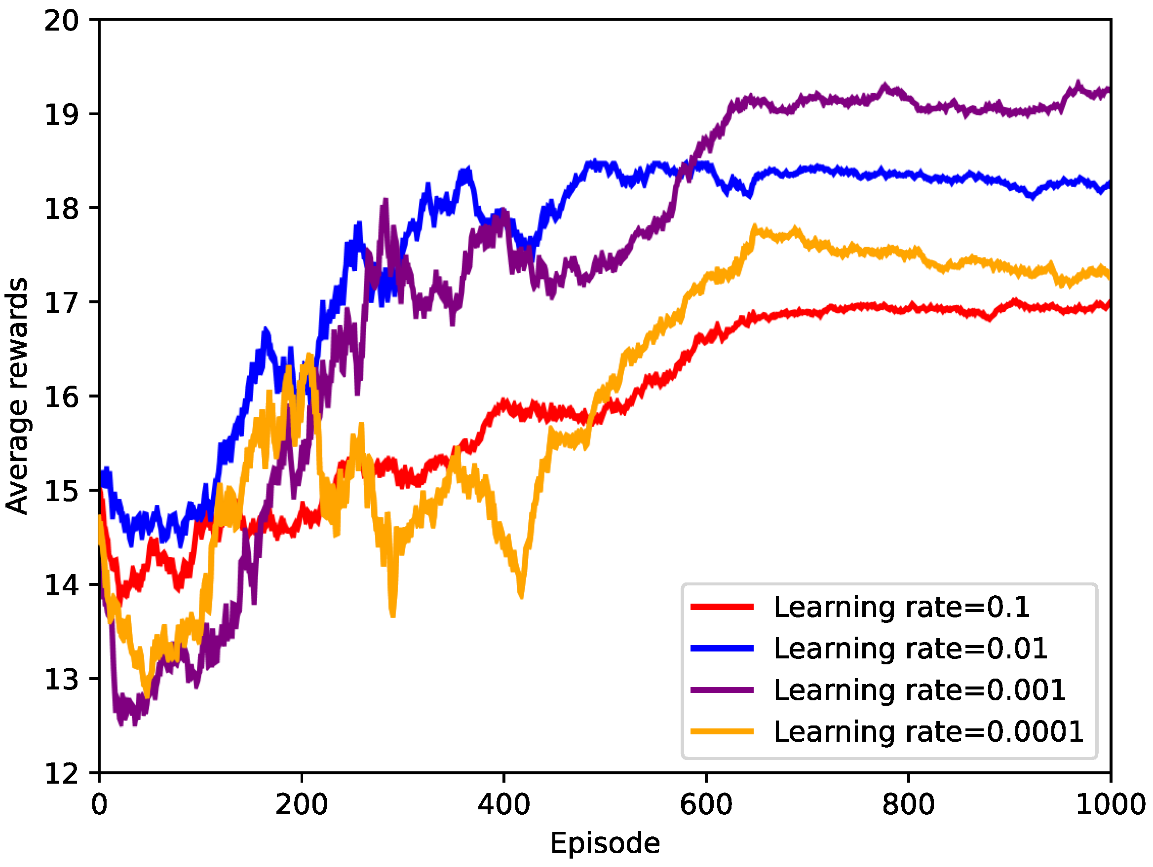
Figure 5 illustrates the effect of various learning rates on the average reward of the proposed DDQN-empowered algorithm [25]. It is clear that different learning rates have a significant impact on the performance of the DRL algorithm. The learning rate actually controls how much the model parameters are updated in each iteration; either too high or too low a learning rate may lead to unstable or poor training. Typically, a small learning rate such as 0.0001 will make the model converge slower, but helps to avoid missing the optimal solution by updating the parameters too much; on the contrary, a larger learning rate can speed up the convergence, but may lead to fluctuation or unstable training process. Notably, the DRL algorithm with a learning rate of 0.001 achieves the best performance, although this may require a longer training time. Meanwhile, the convergence time with learning rate of 0.0001 and 0.00001 is worse compared to the performance when the learning rate is larger (say, 0.1). This is due to the fact that too large a learning rate increases oscillations and causes a sharp drop in performance. Therefore, in DRL-enabled optimization frameworks it is very critical to choose an appropriate learning rate. By trying different values of the learning rate, a balance can be found that allows the model to both converge quickly and achieve better performance during training.

5. Conclusions

This paper introduces a novel system architecture wherein UAVs are equipped with RISs for edge computation with the aim of enhancing the quality of VU offload links and further optimizing the performance of an MEC system. Moreover, a sophisticated optimization framework is proposed to jointly optimize RIS passive beamforming, UAV trajectory planning, and resource allocation using DDQN, with the objective of maximizing the trade-off between weighted energy efficiency and high-quality trajectory visualization. The numerical results presented in this study showcase the significant advantages of leveraging the DRL algorithm for optimizing UAV–RIS-aided MEC systems. The results further highlight the effectiveness of the proposed framework in achieving superior performance compared to traditional optimization methods.

Author Contributions

Conceptualization, M.W., S.Z. and J.Z.; methodology, M.W., S.Z. and C.L.; software, J.Z. and Y.C.; validation, M.W., X.L. and R.L.; formal analysis, X.L. and R.L.; investigation, C.L., X.L. and R.L.; resources, S.Z. and J.Z.; data curation, J.Z, and Y.C.; writing—original draft preparation, X.L., J.Z. and Y.C.; writing—review and editing, M.W., X.L. and R.L.; visualization, C.L., X.L. and R.L.; supervision, M.W., S.Z. and C.L.; project administration, M.W., S.Z. and C.L.; funding acquisition, S.Z. and C.L. All authors have read and agreed to the published version of the manuscript.

Funding

This research was funded by the Research Foundation of the Key Laboratory of Spaceborne Information Intelligent Interpretation 2022-ZZKY-JJ-20-02, and the Electronic Information Equipment System Research National Defense Science and Technology Key Laboratory Fund 2023-HT-04.

Data Availability Statement

Data are contained within this article.

Conflicts of Interest

The authors declare no conflict of interest.

References

  1. Hwang, J.; Nkenyereye, L.; Sung, N.; Kim, J.; Song, J. IoT service slicing and task offloading for edge computing. IEEE Internet Things J. 2021, 8, 11526–11547. [Google Scholar] [CrossRef]
  2. Xia, Y.; Deng, X.; Yi, L.; Tang, L.; Tang, X.; Zhu, C.; Tian, Z. AI-driven and MEC-empowered confident information coverage hole recovery in 6G-enabled IoT. IEEE Trans. Netw. Sci. Eng. 2023, 10, 1256–1269. [Google Scholar] [CrossRef]
  3. Wang, F.; Zhang, X. IRS/UAV-based edge-computing/traffic-offloading over RF-rowered 6G mobile wireless networks. In Proceedings of the IEEE Wireless Communications and Networking Conference (WCNC), Austin, TX, USA, 10–13 April 2022; pp. 1272–1277. [Google Scholar]
  4. Li, M.; Cheng, N.; Gao, J.; Wang, Y.; Zhao, L.; Shen, X. Energy efficient UAV-assisted mobile edge computing: Resource allocation and trajectory optimization. IEEE Trans. Veh. Technol. 2020, 69, 3424–3438. [Google Scholar] [CrossRef]
  5. Xu, Y.; Zhang, T.; Liu, Y.; Yang, D.; Xiao, L.; Tao, M. UAV-assisted MEC networks with aerial and ground cooperation. IEEE Trans. Wirel. Commun. 2021, 20, 7712–7727. [Google Scholar] [CrossRef]
  6. Guo, K.; Wu, M.; Li, X.; Song, H.; Kumar, N. Deep reinforcement learning and NOMA-based multiobjective RIS-assisted IS-UAV-TNs: Trajectory optimization and beamforming design. IEEE Trans. Intell. Transp. Syst. 2023, 24, 10197–10210. [Google Scholar] [CrossRef]
  7. Bai, T.; Pan, C.; Deng, Y.; Elkashlan, M.; Nallanathan, A.; Hanzo, L. Latency minimization for intelligent reflecting surface aided mobile edge computing. IEEE J. Sel. Areas Commun. 2020, 38, 2666–2682. [Google Scholar] [CrossRef]
  8. Yang, Z.; Chen, M.; Liu, X.; Liu, Y.; Chen, Y.; Cui, S.; Poor, H.V. AI-driven UAV-NOMA-MEC in next generation wireless networks. IEEE Wirel. Commun. 2021, 28, 66–73. [Google Scholar] [CrossRef]
  9. Zhang, Q.; Wang, Y.; Li, H.; Hou, S.; Song, Z. Resource allocation for energy efficient STAR-RIS aided MEC systems. IEEE Wirel. Commun. Lett. 2023, 12, 610–614. [Google Scholar] [CrossRef]
  10. Kim, J.; Hong, E.; Jung, J.; Kang, J.; Jeong, S. Energy minimization in reconfigurable intelligent surface-assisted unmanned aerial vehicle-enabled wireless powered mobile edge computing systems with rate-splitting multiple access. Drones 2023, 7, 688. [Google Scholar] [CrossRef]
  11. Zhai, Z.; Dai, X.; Duo, B.; Wang, X.; Yuan, X. Energy-efficient UAV-mounted RIS assisted mobile edge computing. IEEE Wirel. Commun. Lett. 2022, 11, 2507–2511. [Google Scholar] [CrossRef]
  12. Zhuo, Z.; Dong, S.; Zheng, H.; Zhang, Y. Method of minimizing energy consumption for RIS assisted UAV mobile edge computing system. IEEE Access 2024, 12, 39678–39688. [Google Scholar] [CrossRef]
  13. Wu, M.; Guo, K.; Li, X.; Lin, Z.; Wu, Y.; Tsiftsis, T.A.; Song, H. Deep reinforcement learning-based energy efficiency optimization for RIS-aided integrated satellite-aerial-terrestrial relay networks. IEEE Trans. Commun. 2024; early access. [Google Scholar] [CrossRef]
  14. Liu, Y.; Yu, H.; Xie, S.; Zhang, Y. Deep reinforcement learning for offloading and resource allocation in vehicle edge computing and networks. IEEE Trans. Veh. Technol. 2019, 68, 11158–11168. [Google Scholar] [CrossRef]
  15. Ale, L.; Zhang, N.; Fang, X.; Chen, X.; Wu, S.; Li, L. Delay-aware and energy-efficient computation offloading in mobile-edge computing using deep reinforcement learning. IEEE Trans. Cognit. Commun. Netw. 2021, 7, 881–892. [Google Scholar] [CrossRef]
  16. Subburaj, B.; Jayachandran, U.; Arumugham, V.; Amalraj, M. A self-adaptive trajectory optimization algorithm using fuzzy logic for mobile edge computing system assisted by unmanned aerial vehicle. Drones 2023, 7, 266. [Google Scholar] [CrossRef]
  17. Hu, X.; Wong, K.K.; Yang, K.; Zheng, Z. UAV-assisted relaying and edge computing: Scheduling and trajectory optimization. IEEE Trans. Wirel. Commun. 2019, 18, 4738–4752. [Google Scholar] [CrossRef]
  18. Liu, Y.; Xiong, K.; Ni, Q.; Fan, P.; Letaief, K.B. UAV-assisted wireless powered cooperative mobile edge computing: Joint offloading, CPU control, and trajectory optimization. IEEE Internet Things J. 2020, 7, 2777–2790. [Google Scholar] [CrossRef]
  19. Zeng, Y.; Xu, J.; Zhang, R. Energy minimization for wireless communication with rotary-wing UAV. IEEE Trans. Wirel. Commun. 2019, 18, 2329–2345. [Google Scholar] [CrossRef]
  20. Zhang, H.; Huang, M.; Zhou, H.; Wang, X.; Wang, N.; Long, K. Capacity Maximization RIS-UAV Networks: A DDQN-Based Trajectory Phase Shift Optimization Approach. IEEE Trans. Wirel. Commun. 2023, 22, 2583–2591. [Google Scholar] [CrossRef]
  21. Yang, R.; Wang, D.; Qiao, J. Policy gradient adaptive critic design with dynamic prioritized experience replay for wastewater treatment process control. IEEE Trans. Ind. Inf. 2022, 18, 3150–3158. [Google Scholar] [CrossRef]
  22. Zhang, G.; Wu, Q.; Cui, M.; Zhang, R. Securing UAV communications via joint trajectory and power control. IEEE Trans. Wirel. Commun. 2019, 18, 1376–1389. [Google Scholar] [CrossRef]
  23. Yang, H.; Xiong, Z.; Zhao, J.; Niyato, D.; Xiao, L.; Wu, Q. Deep reinforcement learning-based intelligent reflecting surface for secure wireless communications. IEEE Trans. Wirel. Commun. 2021, 20, 375–388. [Google Scholar] [CrossRef]
  24. Zhang, T.; Liu, G.; Zhang, H.; Kang, W.; Karagiannidis, G.K.; Nallanathan, A. Energy-efficient resource allocation and trajectory design for UAV relaying systems. IEEE Trans. Commun. 2020, 68, 6483–6498. [Google Scholar] [CrossRef]
  25. Huang, C.; Mo, R.; Yue, Y. Reconfigurable intelligent surface assisted multiuser MISO systems exploiting deep reinforcement learning. IEEE J. Sel. Areas Commun. 2020, 38, 1839–1850. [Google Scholar] [CrossRef]
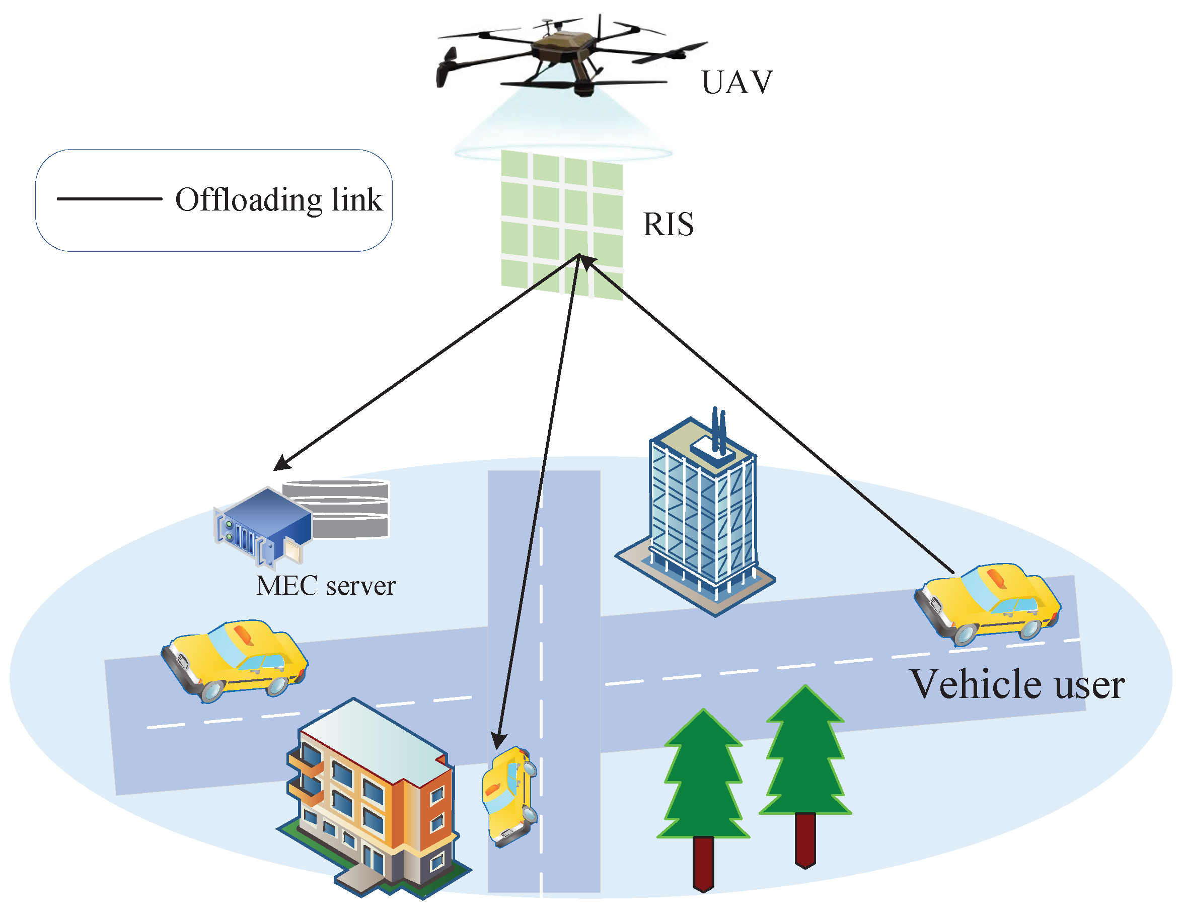
Figure 1. UAV–RIS-aided MEC system model.
Drones 08 00184 g001
Figure 2. The framework of the proposed DDQN-based optimization algorithm.
Drones 08 00184 g002
Figure 3. Comparison of trajectories under different algorithms.
Drones 08 00184 g003
Figure 4. Schematic of weighted energy efficiency versus total time.
Drones 08 00184 g004
Figure 5. Schematic of learning rate versus average rewards.
Drones 08 00184 g005
Table 1. Meaning of key symbols.
SymbolMeaning
h s n C 1 × M The channel gain coefficient from RIS to MEC server
h k n C M × 1 The channel gain coefficient from k-th VU to RIS
q n The position of UAV at the n-th time slots
Θ n The RIS phase shift matrix at the n-th time slots
MThe number of RIS reflective elements
KThe number of ground vehicle users
c k o The aggregate offloaded tasks for k-th VU at the n-th time slots
c k l The locally computed tasks for k-th VU at the n-th time slots
f k o The CPU frequency for aggregate offloaded tasks
f k l The CPU frequency for locally computed tasks
E k o The energy consumption for aggregate offloaded tasks
E k l The energy consumption for locally computed tasks
s k n The content scheduling variables at the k-th VU
Table 2. Simulation parameter settings.
System ParameterValue
Frequency f = 2 GHz
Channel bandwidth B k = 1 MHz
Carrier wavelenghth λ = 750 MHz
Variance of the noise σ 2 = 160 dBm
UAV fixed altitude H R = 150 m
UAV initial position q 0 = [ 100 , 100 ] T
Power allocated to k-th VU p k = 0.1 W
Total offloaded tasks T k = 50
Number of VUs8
Service areas 200 m × 200 m
Number of CPU cycles χ k = 10 3 cycles / bit
Number of RIS relfective elements M = 10 × 10
Time slot length1 s
Disclaimer/Publisher’s Note: The statements, opinions and data contained in all publications are solely those of the individual author(s) and contributor(s) and not of MDPI and/or the editor(s). MDPI and/or the editor(s) disclaim responsibility for any injury to people or property resulting from any ideas, methods, instructions or products referred to in the content.