Article

Online Predictive Visual Servo Control for Constrained Target Tracking of Fixed-Wing Unmanned Aerial Vehicles

College of Intelligence Science and Technology, National University of Defense Technology, Changsha 410073, China
*
Author to whom correspondence should be addressed.
Drones 2024, 8(4), 136; https://doi.org/10.3390/drones8040136
Submission received: 23 February 2024 / Revised: 29 March 2024 / Accepted: 1 April 2024 / Published: 2 April 2024
(This article belongs to the Special Issue Advances in Perception, Communications, and Control for Drones)

Abstract

:
This paper proposes an online predictive control method for fixed-wing unmanned aerial vehicles (UAVs) with a pan-tilt camera in target tracking. It aims to achieve long-term tracking while concurrently maintaining the target near the image center. Particularly, this work takes the UAV and pan-tilt camera as an overall system and deals with the target tracking problem via joint optimization, so that the tracking ability of the UAV can be improved. The image captured by the pan-tilt camera is the unique input associated with the target, and model predictive control (MPC) is used to solve the optimization problem with constraints that cannot be performed by the classic image-based visual servoing (IBVS). In addition to the dynamic constraint of the UAV, the perception constraint of the camera is also taken into consideration, which is described by the maximum distance between the target and the camera. The accurate detection of the target depends on the amount of its feature information contained in the image, which is highly related to the relative distance between the target and the camera. Moreover, considering the real-time requirements of practical applications, an MPC strategy based on soft constraints and a warm start is presented. Furthermore, a switching-based approach is proposed to return the target back to the perception range quickly once it exceeds the range, and the exponential asymptotic stability of the switched controller is proven as well. Both numerical and hardware-in-the-loop (HITL) simulations are conducted to verify the effectiveness and superiority of the proposed method compared with the existing method.

1. Introduction

Target tracking is not only the essential basis for UAVs to perform Earth observation tasks, but also the foundation for subsequent intention analysis and situation generation. It can be applied to border surveillance, urban security, and aerial photography. Compared with a fixed surveillance camera, the field of view (FOV) of the camera is greatly expanded with the aid of a UAV, thereby enhancing the persistent monitoring capability of the target. Moreover, considering that fixed-wing UAVs usually exhibit longer endurance and faster flight speed than multi-rotor UAVs, it is meaningful to study target tracking for fixed-wing UAVs.
With the aid of vision sensors, the visual servoing method can be adopted to achieve target tracking. Based on the difference in feedback information, the method is mainly divided into two categories: position-based visual servoing (PBVS) and IBVS [1]. In terms of PBVS, it is required to calculate the relative position of the target to the UAV after obtaining the feature information of the target. Li et al. [2] achieved the passive vision-based tracking and motion estimation of a ground vehicle, which provided real-time estimation of the position, speed, and heading of the target. By designing a nonlinear adaptive observer to estimate the states, parameters, and the position of the target, Choi et al. [3] proposed a guidance law for target tracking and UAV maneuvers for a persistent excitation condition. Furthermore, Wang et al. [4] conducted actual flight tests to verify the proposed framework for tracking a mobile ground target. Nevertheless, due to the inevitable errors caused by camera calibration, there usually exist positioning deviations in PBVS which affect tracking accuracy.
In comparison, IBVS bypasses the positioning stage and directly designs the controller for the UAVs in the image plane. Therefore, it is robust to sensor models and calibration errors. Based on this method, Le Bras et al. [5] proposed a control algorithm to stabilize a UAV along a circular trajectory using a single visual landmark, which did not require independent position or velocity measurements. Similarly, Peliti et al. [6] proposed a feedback control approach aimed at guiding the UAV along a circular trajectory centered above the target, and a method that integrates IBVS using the least square method (LSM) is presented in our previous work [7] to enable continuous target tracking. Triputra et al. [8] presented a full dynamic visual servoing flight controller design using a command filtered backstepping control law for a fixed-wing UAV, which enables it to perform target tracking and the pursuing task effectively.
However, the IBVS method just focuses on the motion of the image feature information, but is unable to handle the constraints. For example, the dynamic constraint of the fixed-wing UAV and the visibility constraint of the vision sensors cannot be taken into consideration. As a result, the optimal solution may not be obtained; even worse, the target will be out of sight during tracking. To address this, MPC was introduced to solve the optimization problem with constraints, thereby improving the performance of the IBVS method. By combining standard MPC with IBVS, refs. [9,10,11] paid attention to the image kinematics and solved the constrained visual servoing problem for a 6-degrees-of-freedom (DOF) camera. Furthermore, refs. [12,13,14] took the dynamics of the 6-DOF system into consideration, which solved the visibility constraint and dynamic constraint at the same time. With regard to systems with uncertain or unknown parameters, refs. [15,16] integrated adaptive MPC and IBVS to improve the accuracy and stability of the control system. Furthermore, refs. [17,18] adopted a robust MPC to enhance the robustness of the IBVS system to uncertainty and interference. However, all of the above investigations are based on a full actuated system.
At present, there still exist very few investigations of MPC-based IBVS used in UAVs that are underactuated. This is mainly due to the challenge of concurrently considering the complex dynamic model of the UAV, the nonlinear IBVS system, and real-time requirements. Among related works, ref. [19] proposed an observer-based MPC scheme for the IBVS of a quadrotor, the objective of which was to regulate the relative pose of the quadrotor to a planar ground target using a monocular camera and an inertia measurement unit. In order to produce safe control inputs of the quadrotor in an obstacle-containing environment, ref. [20] designed a model predictive IBVS scheme by optimizing a cost function of the predicted image trajectories under the constraints of visibility and velocity. In addition, ref. [21] proposed a robust nonlinear MPC scheme for the visual servoing of quadrotors subject to external disturbances. Note that all of the above works are based on quadrotors. However, due to the highly dynamic nature of the moving target and fixed-wing UAV, it is challenging to achieve target tracking based on the real-time MPC-based IBVS method. It is imperative that the method demonstrates satisfactory real-time performance to be viable for online deployment. To the best of our knowledge, there is still a lack of relevant studies.
In this paper, we propose an online MPC-based IBVS method for a fixed-wing UAV in target tracking. With the aid of the method, the UAV is able to achieve persistent tracking of the target. Simultaneously, a pan-tilt camera is controlled to keep the target near the image center. Given the limited perception capability of the camera, when the target is far away from the camera, it may not be detected correctly due to the lack of image feature information. To this end, an MPC is adopted to consider both the perception constraint of the camera and the dynamic constraint of the fixed-wing UAV. Furthermore, considering that the target may exceed the clear perception range of the camera with increase in its speed, a switching-based control strategy is designed to quickly return the target to the perception range. Last but not least, both numerical and HITL simulations are conducted to verify the feasibility and superiority of the proposed method. The contributions of this paper are summarized as follows:
  • A novel MPC-based IBVS method is proposed for the integrated system comprising a fixed-wing UAV and a pan-tilt camera in target tracking, with a focus on the camera’s perception capability. In contrast to prior research on target tracking [5,6,7,8], our method ensures that the target remains within the clear perception range, facilitating the generation of more image feature information for accurate detection.
  • A switching-based MPC strategy incorporating soft constraints and a warm start is developed to ensure real-time performance in practical applications. By enabling smooth transitions between the different optimization controllers, this strategy empowers the UAV to promptly approach the target once it exceeds the camera’s clear perception range, thereby ensuring continuous tracking. Moreover, the stability of the closed-loop system is demonstrated.
  • Extensive simulations, including numerical and HITL simulations, are conducted to verify the effectiveness and superiority of the proposed method compared with the existing method.

2. Problem Statement

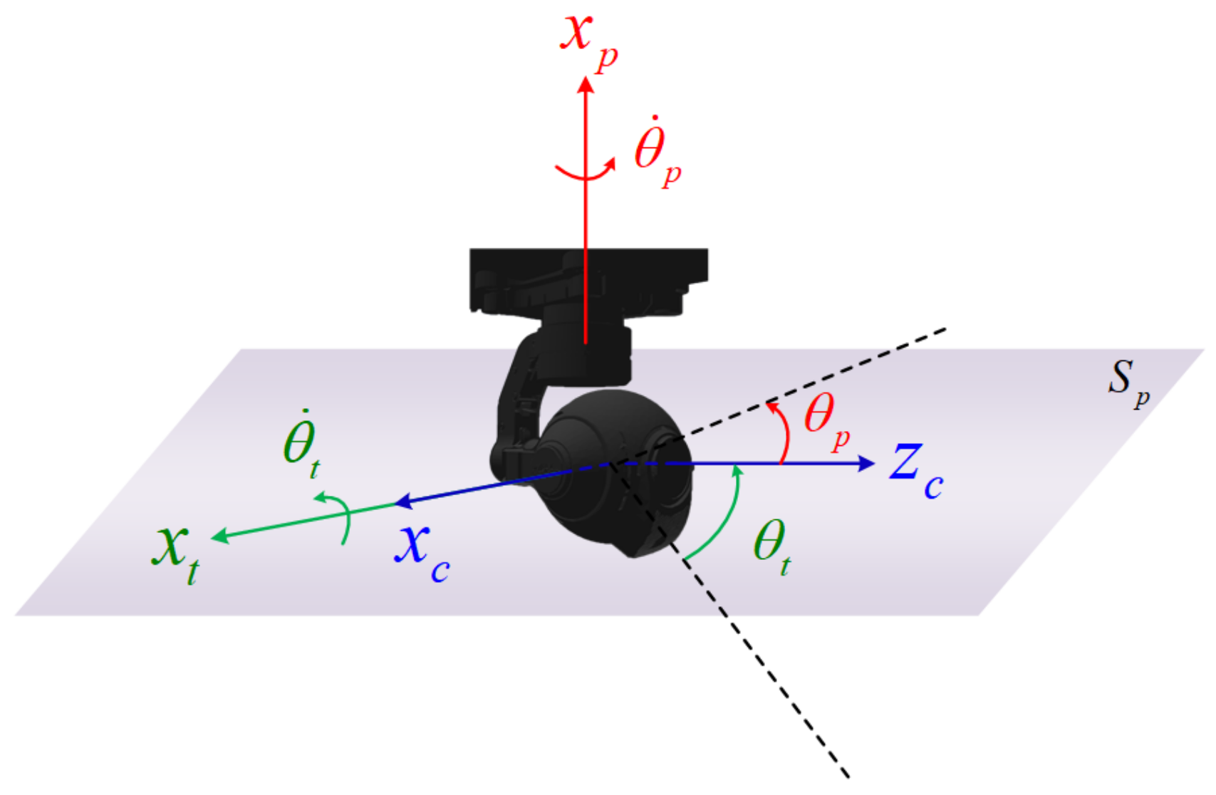
The paper aims to achieve target tracking for a fixed-wing UAV using a pan-tilt camera based on a method combining MPC and IBVS. As Figure 1 shows, the UAV can circle around the target and concurrently keep the target near the image center with the aid of the pan-tilt camera. Note that the position and motion of the target considered in this work is unknown to the UAV, and the only source of the information about the target is the image captured by the pan-tilt camera. In terms of the pan-tilt camera, it has 2-DOF that can rotate in the horizontal and vertical planes, as shown in Figure 2. Three different frames are primarily involved. The body frame F b = { o b , x b , y b , z b } is fixed on the UAV, where o b is located at the center of gravity of the fixed-wing UAV and the x b -axis points to the head direction of the UAV. The origin o c of the camera frame F c = { o c , x c , y c , z c } lies at the optical center, and the z c -axis is along the optic axis. As for the image frame F i = { o i , x i , y i } , its x i -axis and y i -axis are parallel to the x c -axis and the y c -axis, respectively.

2.1. System Modeling

The system used here is composed of a fixed-wing UAV and a pan-tilt camera. In contrast to rotor UAVs that are capable of executing various maneuvers [22,23], fixed-wing UAVs are constrained by the minimum stall speed and the turning radius. Therefore, they are assumed to fly at a constant speed and altitude in this study. The configuration used has been commonly employed in research on formation control [24] and path following [25]. Moreover, the unicycle model can be adopted to analyze the kinematics of the UAV. Denote the flight speed and altitude of the UAV by V t and H, respectively. The yaw, pitch, and roll angles of the UAV are denoted by ψ , θ , and ϕ , respectively. Then, the UAV model can be represented as
V x = V t · c o s ψ , V y = V t · s i n ψ , ψ ˙ = u ψ ,
where u ψ is the control input of the UAV. It is noted that the model is also used in [24,25].
Next, the pan-tilt camera with 2-DOF is modeled, which is shown in Figure 2. Denote the horizontal plane by S p , and the x t -axis lies in S p , while the x p -axis is perpendicular to S p . Correspondingly, the pitch angle and the yaw angle of the pan-tilt are denoted by θ t and θ p , respectively. Specifically, this paper adopts a pan-tilt with omnidirectional deflection around the x p -axis. Therefore, the pan-tilt model can be represented as
θ p ˙ = u p , θ p [ γ p , γ p ] θ t ˙ = u t , θ t [ γ 1 , γ 2 ]
where u p and u t are the control inputs of the pan-tilt, and γ 1 > π 2 while γ 2 > 0 . Note that θ t = 0 when the z c -axis lies in S p , as shown in Figure 2.
To sum up, we have the following overall system composed of a UAV and a pan-tilt camera:
V x = V t · c o s ψ V y = V t · s i n ψ ψ ˙ = u ψ θ p ˙ = u p , θ p [ π , π ] θ t ˙ = u t , θ t [ γ 1 , γ 2 ]
Problem 1.
How to design a controller for the overall system composed of a fixed-wing UAV and a pan-tilt camera based on the model of (3), such that the target will not be beyond the field of view or far away from the UAV to make it undetectable, and the UAV can achieve long-term tracking of the fast moving target while keeping it near the image center?

2.2. Image Kinematics

This part aims to construct the image kinematic model so that it can be used to predict the future behavior of the feature point during the process of the MPC. Denote the coordinates of the target in F c and F i by ( x c , y c , z c ) and ( u i , v i ) , respectively. According to the triangle similarity, there exists the following relationship:
u i x c = v i y c = f z c ,
where f represents the focal length.
Furthermore, the motion of the camera needs to be taken into consideration. Denote the linear velocity vector along the three axes of F c by V c = [ V x , V y , V z ] . Simultaneously, the corresponding angular velocity vector is denoted by Ω c = [ ω x , ω y , ω z ] . Let s i = [ u i , v i ] ; then, the following equation can be obtained based on [1]:
s ˙ i = L s · V c Ω c ,
where L s R 2 × 6 is called an image Jacobian matrix, which is equal to
L s = f z c 0 u i z c u i v i f f 2 + u i 2 f v i 0 f z c v i z c f 2 + v i 2 f u i v i f u i .

3. Controller Design

3.1. MPC Optimization Problem Formulation

This part aims to solve Problem 1.
Based on our previous work [7], a reference state named the Ideal State was proposed to construct the relationship between the image feature vector and u ψ . As for the reference state, it has the following constant state:
θ p = π 2 , θ t = α , θ = 0 , ϕ = 0 .
Note that α ( 0 , π 2 ] is a given constant. When given the desired circling radius R d , α can be expressed as α = arctan ( H R d ) . Denote the coordinates of the feature point in F i by ( u 1 , v 1 ) , and in the reference state by ( u 2 , v 2 ) ; then, the relationship can be written as:
u ˙ 2 v ˙ 2 = f 2 + u 2 2 f · c o s α v 2 · s i n α f z c u 2 · v 2 f · c o s α + u 2 · s i n α 0 · u ψ V t .
Simultaneously, u p and u t can be obtained from (20) in [7], which is
u p = arctan ( u ˙ 1 f ) , u t = arctan ( v ˙ 1 f ) .
Define s 2 = [ u 2 , v 2 ] and based on (8), the discrete time state-space model can be expressed as
s 2 ( k + 1 ) = s 2 ( k ) + s ˙ 2 ( k ) · Δ t ,
where Δ t is the sampling time.
For convenience of subsequent analysis, the discrete form is rewritten as
s 2 ( k + 1 ) = f s ( s 2 , u ψ , k ) ,
Since the yaw rate of the fixed-wing UAV is restricted, then the following constraint needs to be satisfied:
u ψ U s e t , U s e t = [ u max , u max ] .
In order to guarantee that the change in u ψ can be smooth, the acceleration constraint is also given:
Δ u ψ a s e t , a s e t = [ a max , a max ] .
where
Δ u ψ ( k + i ) = u ψ ( k + i ) u ψ ( k + i 1 ) .
Furthermore, the perception capability of the camera is taken into consideration as well. Under the condition of invariant camera parameters, whether the target can be detected correctly usually depends on the amount of feature information contained in the image. More specifically, it is related to the maximum perceived distance of the camera, which is denoted by L M . Therefore, the clear perception range of the camera is equivalent to a cone, as shown in Figure 3.
In order to determine whether the target is within the cone, the feature point in the current image plane is first mapped into that in the horizontal image plane. Define the feature point in the latter plane as ( u 3 , v 3 ) , considering that θ t = α of (7) in the Ideal State; then, ( u 3 , v 3 ) can be obtained from ( u 2 , v 2 ) based on the following transformation:
u 3 v 3 f = k 3 1 0 0 0 sin α cos α 0 cos α sin α u 2 v 2 f ,
where k 3 R + . After solving the above three equations, the value of u 3 and v 3 can be obtained.
Since the flight altitude H of the UAV is constant in this paper, the maximum perceived distance can be converted into the maximum horizontal distance, which is denoted by R M . Therefore, the target is recognized to be within the perception range if, and only if, the following condition is met:
u 3 2 + v 3 2 f R M H .
After that, in order to keep the target within the perception range when the UAV circles around it, α in (7) needs to satisfy the following condition:
tan ( π 2 α ) R M H ,
Simultaneously, considering the constraint of u ψ in (12), there exists
tan ( π 2 α ) V t u max · H .
Define η 1 = arctan R M H , η 2 = arctan V t u max · H , then α [ π 2 η 1 , π 2 η 2 ] . Based on (16), the perception constraint at time-step k can be defined as
g 1 ( k ) 0 ,
where
g 1 : = u 3 2 + v 3 2 f 2 R M 2 H 2
Denote the error of the feature point by
Δ s 2 ( i | k ) = s d s 2 ( i | k ) ,
where s d = [ 0 , 0 ] is the desired value of s 2 , and s 2 ( 0 | k ) = s 2 ( k ) is the observed value at time-step k. Since Δ u ψ ( 0 | k ) = u ψ ( 0 | k ) u ψ ( k 1 ) , then the cost function can be defined as follows:
J 1 ( k ) = i = 1 N p Δ s 2 ( i | k ) Q s 2 + Δ u ψ ( i 1 | k ) Q u 2 = i = 1 N p J r ( i | k ) ,
where Δ s 2 Q s 2 = Δ s 2 · Q s · Δ s 2 and similar to Δ u ψ Q u 2 , Q s = d i a g { q 1 , q 2 } is positive definite and Q u R + . The control sequence is
U = { u ψ ( 0 | k ) , u ψ ( 1 | k ) , , u ψ ( N p 1 | k ) } ,
N p R + is the prediction horizon.
Note that J 1 = 0 if, and only if, Δ s 2 ( i | k ) = 0 and Δ u ψ ( i 1 | k ) for i { 1 , , N p } . That is, the constant control input of the UAV makes it circle around the static target.
Due to the fact that only the first control input of U in (23) is used, the following contraction constraint is provided to ensure the stability of the system (which will be proven in Section 3.3):
C C 1 ( k ) = Δ s 2 ( 1 | k ) δ · Δ s 2 ( k ) 0 ,
where Δ s 2 ( k ) represents the 2-norm of s 2 ( k ) , δ ( 0 , 1 ) .
Therefore, based on Equations (11)–(13), (19), (22), and (24), the MPC optimization problem can be formulated as
P 1 : arg min U ( k ) J 1 ( k )
s . t . s 2 ( i | k ) = f s s 2 , u ψ , i 1 | k ,
u ψ ( i 1 | k ) U s e t ,
Δ u ψ ( i 1 | k ) a s e t ,
g 1 ( i | k ) 0 ,                  
C C 1 ( k ) 0 ,                  
where i = 1 , 2 , , N p .

3.2. Switching-Based Optimization Control

Problem 2.
With the increase in N p and limited by the computing capability of the processors, it is time-consuming to solve the optimization problem of (25) with nonlinear hard constraints (25e) and (25f) online. Even worse, they may also lead to the problem of an infeasible solution within the predefined iterations. Then, the question arises of how to design an online MPC strategy for practical application?
To solve the problem, this paper considers adding the hard constraints into the cost function, so that these constraints need not be strictly satisfied.
Firstly, add the constraint (25e) into J r ; then, we have
J r , 1 ( i | k ) = J r ( i | k ) + β 1 · max { g 1 ( i | k ) , 0 } ,
where β 1 R + is a constant.
Remark 1.
In the context of discrete systems as addressed in this work, the discontinuous nature of the sampling points renders the exact occurrence at g 1 ( i | k ) = 0 highly improbable. Furthermore, it is essential to acknowledge that the cost function focuses on the overall optimization objective, thus rendering the non-differentiability of specific points inconsequential to the overall optimization.
Furthermore, considering the constraints of (12), (13), and the unknown motion of the target, it may be unable to make g 1 ( k + 1 ) 0 when g 1 ( k ) > 0 . Therefore, g 1 in (20) is redefined as follows to make β 1 · max { · } in (26) function earlier:
g 2 : = u 3 2 + v 3 2 f 2 ( R M Δ R ) 2 H 2 ,
where Δ R > 0 . Then, (26) is rewritten as
J r , 1 ( i | k ) = J r ( i | k ) + β 1 · max { g 2 ( i | k ) , 0 } ,
After that, turn (24) into a soft constraint as well; then, the cost function can be represented as
J 1 , s o f t ( k ) = i = 1 N p J r , 1 ( i | k ) + β 2 · max { C C 1 ( k ) , 0 } .
Compared with the soft constraints-based method that introduces slack variables like [26], the method that uses the max function is more efficient. When g 2 ( i | k ) 0 is satisfied, the nonlinear function does not participate in solving the gradient in each iteration when using the interior point method. However, the gradients of all the g 2 ( i | k ) still need to be calculated in each iteration for the former method, which is more time-consuming.
Therefore, the MPC optimization problem can be reformulated as
P 1 , s o f t : arg min U ( k ) J 1 , s o f t ( k )
s . t . s 2 ( t | k ) = f s s 2 , u ψ , i 1 | k ,
u ψ ( i 1 | k ) U s e t ,          
Δ u ψ ( i 1 | k ) a s e t ,          
where i = 1 , 2 , , N p .
A warm start is also used in this work. Based on our previous work [7], the control input for the UAV can be obtained with the aid of LSM and (11), which is denoted by u ψ ( i | 0 ) , i = 0 , , N p 1 . Note that u ψ i U s e t is required; then, the initial control sequence can be chosen as
U 0 = { u ψ ( 0 | 0 ) , u ψ ( 1 | 0 ) , , u ψ ( N p 1 | 0 ) } .
Obviously, U 0 satisfies the inequality constraints of (30c) and (30d). This indicates that U 0 is the feasible solution of the optimization problem.
Furthermore, denote the optimal solution at time-step k by U ( k ) ; then, the feasible solution at time-step k + 1 , denoted by U ( k + 1 ) , can be chosen as
u ψ ( i | k + 1 ) = u ψ ( i + 1 | k ) , i = 0 , , N p 2 u ψ ( N p 1 | k ) , i = N p 1
With increase in the target speed, the relative distance between the fixed-wing UAV and the target may exceed the maximum perceived distance limited by the constraints of (12) and (13). Although the target may still be recognized with the aid of a detection algorithm, the accuracy of detection will decline and the details of the target cannot be clearly distinguished. It is noted that investigating the details of the target is a basic need for UAV target tracking applications.
The items of β 1 · max { g 2 ( i | k ) , 0 } ( i = 1 , , N p ) in the cost function J r , 1 of (28) help to avoid the relative distance from exceeding R M . However, the optimization problem of (30) is still more concerned with the convergence of s 2 . Moreover, both the gradients about ( u 2 , v 2 ) and ( u 3 , v 3 ) need to be calculated online, which increases the workload of computation.
To solve the problem, a switching-based control method is proposed. When the relative distance keeps within the maximum perceived distance, the optimization problem (30) is considered to enable the UAV to fly around the target. However, if the condition is unsatisfied, the other optimization problem is designed to return the target back to the perception range quickly.
According to (16), the perception constraint is directly affected by ( u 3 , v 3 ) . However, the optimization problem P 1 , s o f t focuses on the convergence of ( u 2 , v 2 ) to s d . Therefore, in order to accelerate the convergence of g 1 ( k ) to 0 once the perception constraint is unsatisfied, a new cost function is defined as follows:
J g ( k ) = i = 1 N p Δ s 3 ( i | k ) Q s , g 2 + Δ u ψ ( i 1 | k ) Q u 2 = i = 1 N p l g ( i | k ) ,
where Q s , g = d i a g { q 1 , g , q 2 , g } is positive definite, Q u R + and
s 3 = [ u 3 , v 3 ] , Δ s 3 ( i | k ) = s d s 3 ( i | k ) .
In addition, to ensure the convergence of Δ s 3 , the following contraction constraint is also given:
C C g ( t | k ) = Δ s 3 ( 1 | k ) δ · Δ s 3 ( k ) 0 ,
where Δ s 3 ( k ) represents the 2-norm of Δ s 3 ( k ) . Similar to (29), in order to avoid the nonlinear constraint of (35), the cost function of J g ( k ) in (33) is rewritten as
J g , s o f t ( k ) = i = 1 N p l g ( i | k ) + β g · max { C C g ( k ) , 0 } ,
where β g R + .
Remark 2.
The convergence of C C 1 in (24) does not theoretically guarantee the convergence of C C g in (35) around g 1 ( k ) = 0 . Only when u 2 2 and v 2 2 converge simultaneously can the convergence of (35) be ensured (refer to Section 3.3 for the proof), thereby ensuring the stability of the switching process.
To this end, a new contractive constraint is defined as follows:
C C 2 a = | Δ u 3 ( 1 | k ) | δ · | Δ u 3 ( k ) 0 , C C 2 b = | Δ v 3 ( 1 | k ) | δ · | Δ v 3 ( k ) 0 .
Referring to (36), the corresponding cost function can be written as
J 2 , s o f t ( k ) = t = 1 N p l g ( t | k ) + a 2 · max { C C 2 a ( k ) , 0 } + max { C C 2 b ( k ) , 0 } .
Considering that (37) necessitates the simultaneous convergence of both | u 2 | and | v 2 | , whereas (35) only mandates the convergence of s 3 , it is evident that the solution requirements for the former are more stringent. By comprehensively considering the stability of the switching process and alleviating the solution constraints, we reformulate the control optimization problem based on Equations (30), (36), and (38) as
P s w i t c h : arg min U ( k ) J s w i t c h ( k )
s . t . s 2 ( t | k ) = f s s 2 , u ψ , t 1 | k ,    
u ψ ( t 1 | k ) U s e t ,
Δ u ψ ( t 1 | k ) a s e t ,    
where t = 1 , 2 , , N p , and
J s w i t c h = J 1 , s o f t ( k ) , n 1 = 0 , J 2 , s o f t ( k ) , 0 < n 1 < n max , J g , s o f t ( k ) , n 1 = n max
Note that n 1 Z + functions as a counter that increases by one when g 1 ( k ) 0 and resets to 0 when g 1 ( k ) > 0 . Moreover, n max Z + represents the counting threshold. The constraint (35) is employed to relax the solution limit only after n 1 reaches n max , thereby mitigating the potential issue of an unstable switching process.
The update of n 1 is formulated as
n 1 = sat ( n 1 + 1 ) , g 1 ( k ) 0 , n 1 = 0 , g 1 ( k ) > 0 ,
where the saturation function s a t ( · ) is defined as
sat ( x ) = n max , x > n max , x , e l s e .
The initialization of n 1 is as follows:
n 1 = n max , g 1 ( 0 ) < 0 , n 1 = 0 , e l s e ,
The implementation of the proposed method is shown as Algorithm 1.
Algorithm 1:Switching-based optimization control for target tracking
Require: The image captured by camera
Ensure: ( u 1 , v 1 ) 0 , ( u 2 , v 2 ) 0
    1:
Let k = 0 , calculate g 1 ( 0 ) , and initialize n 1 based on (43).
    2:
while Discover the target do
    3:
   Detect the centroid coordinates ( u 1 , v 1 ) ;
    4:
   Calculate ( u 2 , v 2 ) of the reference state (7);
    5:
   if  k = 0  then
    6:
     Obtain initial control sequence U ( k ) based on (31).
    7:
   else
    8:
     Obtain initial control sequence U ( k ) based on (32).
    9:
   end if
    10:
   Solve the optimization problem (39) online to obtain U ( k ) .
    11:
   Choose the first element of U ( k ) to be the control input.
    12:
    k = k + 1 .
    13:
   Obtain the control input of the pan-tilt based on (9).
    14:
   Calculate g 1 ( k ) and update n 1 based on (41).
    15:
end while

3.3. Stability Analysis

Theorem 1.
Based on the model of (11), given the contractive constraints (24), (35), and (37), the control input obtained from the control optimization problem (39) ensures the stability of the closed-loop system.
Proof. 
Since (39) is a switching-based control optimization problem, then the stability analysis is divided into three parts, which correspond to the steps when g 1 ( k ) > 0 , g 1 ( k ) 0 for the switching process.
(1) g 1 ( k ) > 0
Based on (35), there exists the following relationship:
Δ s 3 ( k + 1 ) δ · Δ s 3 ( k ) δ k + 1 · Δ s 3 ( 0 ) .
When δ ( 0 , 1 ) , there exists e ( δ 1 ) δ ; then, we have
e ( δ 1 ) k δ k 0 , k Z + .
Substitute (45) into (44) and we obtain
Δ s 3 ( k + 1 ) Δ s 3 ( 0 ) · e ( 1 δ ) ( k + 1 ) .
Since lim k e ( 1 δ ) ( k + 1 ) 0 and Δ s 3 ( k + 1 ) 0 , then
lim k Δ s 3 ( k + 1 ) 0 .
Due to Δ s 3 ( k ) = s 3 ( k ) , then
lim k s 3 ( k ) 0 .
This implies that s 3 will exponentially converge until the condition g 1 ( k ) 0 is met.
(2) g 1 ( k ) 0
When 0 < n 1 < n max , the contractive constraint (24) takes effect, resulting in the following inequalities:
Δ s 2 ( 1 | k ) δ · Δ s 2 ( k ) 0 .
By referring to (44) and (45), we obtain
Δ s 2 ( k + 1 ) Δ s 2 ( 0 ) · e ( 1 δ ) ( k + 1 ) .
Consequently, it follows that
lim k s 2 ( k ) 0 ,
indicating an exponential convergence of s 2 to 0.
Moreover, the norm of s 2 is expressed as
s 2 ( k + 1 ) = u 2 ( k + 1 ) 2 + v 2 ( k + 1 ) 2 ,
When n 1 = n max , the contractive constraint (37) comes into play, leading to the following relationship based on (52):
s 2 ( k + 1 ) δ 2 · u 2 ( k ) 2 + v 2 ( k ) 2 = δ · s 2 ( k ) ,
thus demonstrating exponential convergence in accordance with (50) and (51).
(3) The switching process
According to (15), u 3 and v 3 can be expressed as
u 3 = f · u 2 v 2 · cos α + f · sin α , v 3 = f · ( v 2 · sin α f · cos α ) v 2 · cos α + f · sin α .
Then, we have
u 3 2 + v 3 2 = f 2 · u 2 2 + ( v 2 · sin α f · cos α ) 2 ( v 2 · cos α + f · sin α ) 2 = f 2 · u 2 2 + v 2 2 + f 2 ( v 2 cos α + f · sin α ) 2 ( v 2 · cos α + f · sin α ) 2 = f 2 · ( u 2 2 + v 2 2 + f 2 ) ( v 2 · cos α + f · sin α ) 2 f 2 .
Based on (55), the derivative of u 3 2 + v 3 2 with respect to u 2 2 is
( u 3 2 + v 3 2 ) u 2 2 = f 2 ( v 2 · cos α + f · sin α ) 2 > 0 .
This indicates that u 3 2 + v 3 2 is positively correlated with u 2 2 .
Since v 2 < 0 when s 2 is near the area defined by g 1 = 0 , then we can first solve the derivative of u 3 2 + v 3 2 with respect to v 2 , which is
( u 3 2 + v 3 2 ) v 2 = f 2 · ( v 2 · cos α + f · sin α ) 2 · ( 2 v 2 ) ( v 2 · cos α + f · sin α ) 4 f 2 · ( u 2 2 + v 2 2 + f 2 ) · 2 ( v 2 · cos α + f · sin α ) · cos α ( v 2 · cos α + f · sin α ) 4 = 2 f 2 · ( v 2 · cos α + f · sin α ) · v 2 ( u 2 2 + v 2 2 + f 2 ) · cos α ( v 2 · cos α + f · sin α ) 3 = 2 f 2 · f · v 2 · sin α ( u 2 2 + f 2 ) · cos α ( v 2 · cos α + f · sin α ) 3 .
It is noted that sin α > 0 and cos α > 0 , then
f · v 2 · sin α ( u 2 2 + f 2 ) · cos α < 0 .
Simultaneously, there exists arctan ( v 2 f ) < α according to the definition of α , which can be rewritten as
v 2 · cos α + f · sin α > 0 .
Substituting (58) and (59) into (57), we have
( u 3 2 + v 3 2 ) v 2 < 0 .
Considering that v 2 < 0 , then u 3 2 + v 3 2 is also positively correlated with v 2 2 . Therefore, if both u 2 2 and v 2 2 are convergent when v 2 < 0 , then Δ s 3 is convergent. □

4. Numerical Simulations and Results

In the numerical simulations, the parameters are set as Table 1 shows. Simultaneously, for convenience of the following analysis, the target speed and relative horizontal distance between the target and UAV are denoted by V c and R, respectively. The initial position and bearing of the UAV in the global frame are ( 85 , 0 , 50 ) and π 2 , while the initial position of the target lies at the origin. Note that the fmincon function in MATLAB is adopted to solve the MPC problem.

4.1. Comparative Experiments of the LSM Method [7] and the Proposed Method

This part compares the tracking effects of the UAV for a moving target with V c = 7 m/s by the LSM method and the proposed method of (39). The simulation results for them are shown in Figure 4. Figure 4a intuitively shows the tracking trajectories of the UAVs. Figure 4b provides the details of control. It can be found that u ψ of the proposed method does not change as smoothly as that of the LSM method, which is to trade off the benefits between making s 2 tend to s d and keeping the target within the perception range. It is obvious that R corresponding to the LSM method exceeds R M in Figure 4c, where R M is represented by the black dashed line. However, R corresponding to the proposed method is always less than R M . Furthermore, the changes in s 2 are analyzed as well. Here, we introduce the root mean square error (RMSE) to analyze the deviations, which is defined as RMSE = 1 N i = 1 N Δ s 2 ( i ) 2 2 , where N represents the total sampling number. After calculating, it can be obtained that the RMSE ( L S M ) 226.55 of the LSM method is significantly larger than the RMSE ( p r o ) 153.63 of the proposed method (unit: px), which decreases by 32.19%. Therefore, the above comparisons confirm the superiority of the proposed method over the LSM method in target tracking.

4.2. Comparative Experiments of P 1 , s o f t and the Proposed Method

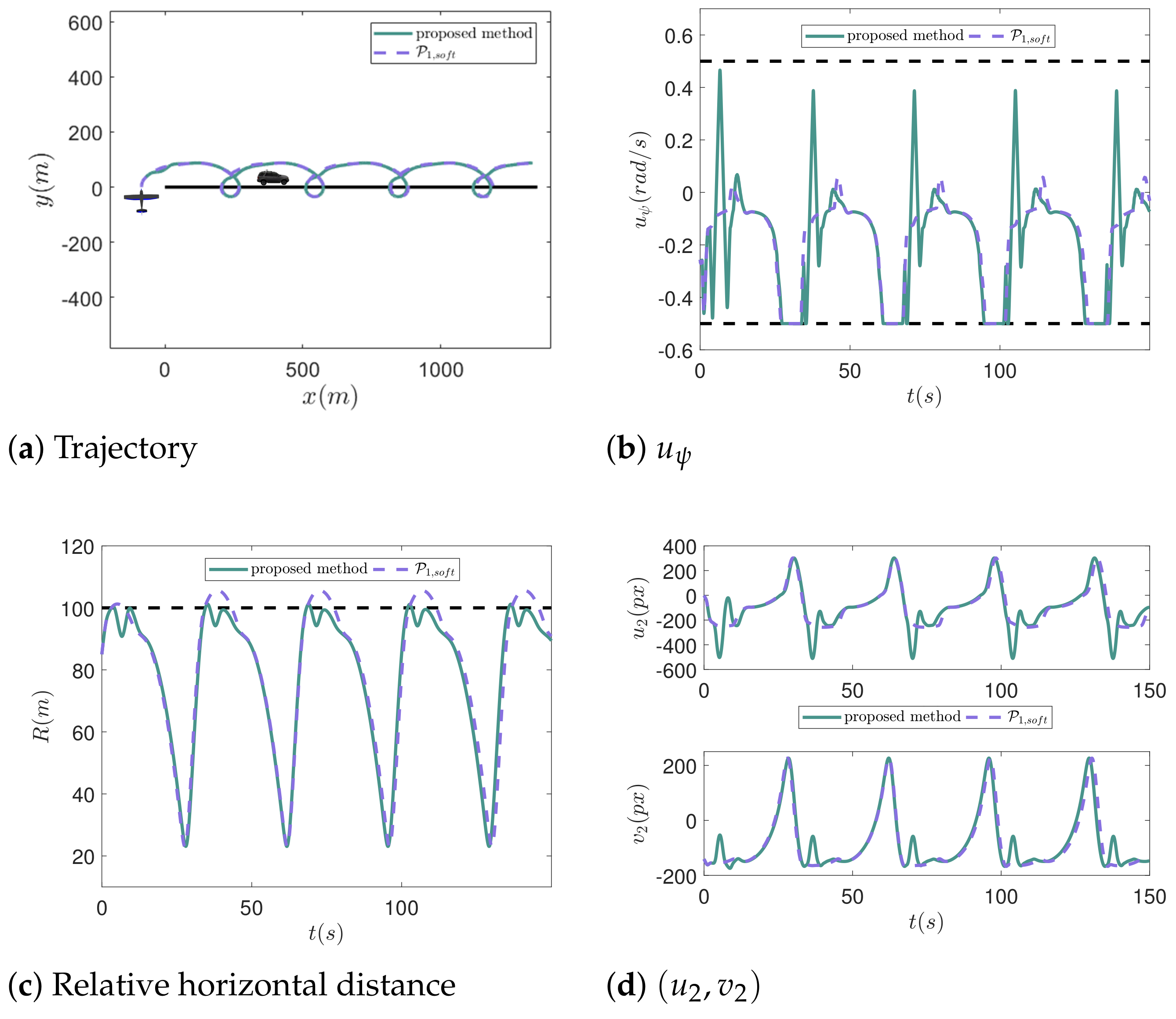
This part compares the tracking effects of the UAV for a moving target with V c = 9 m/s by the proposed method of (39) and P 1 , s o f t of (30) without switch. The corresponding simulation results are shown in Figure 5. When the relative horizontal distance exceeds R M , the UAV is expected to reenter the perception range as soon as possible. It can be found that R corresponding to the method of (30) in Figure 5c exceeds R M , and each time out of the perception range is larger than 9 s. However, once R exceeds R M , it will soon drop below R M under the action of the proposed method. Furthermore, in order to analyze the deviations from s 2 to s d , the RMSE is taken into consideration as well. It can be calculated that the RMSE ( P 1 , s o f t ) 228.56 while the RMSE ( p r o ) 238.38 (unit: px), which just increases by 4.3%. To sum up, compared with the method of (30) without the switch, the proposed method enables the target to quickly return to the perception range with little increase in the RMSE.

4.3. Comparative Experiments on Complex Movements of the Target

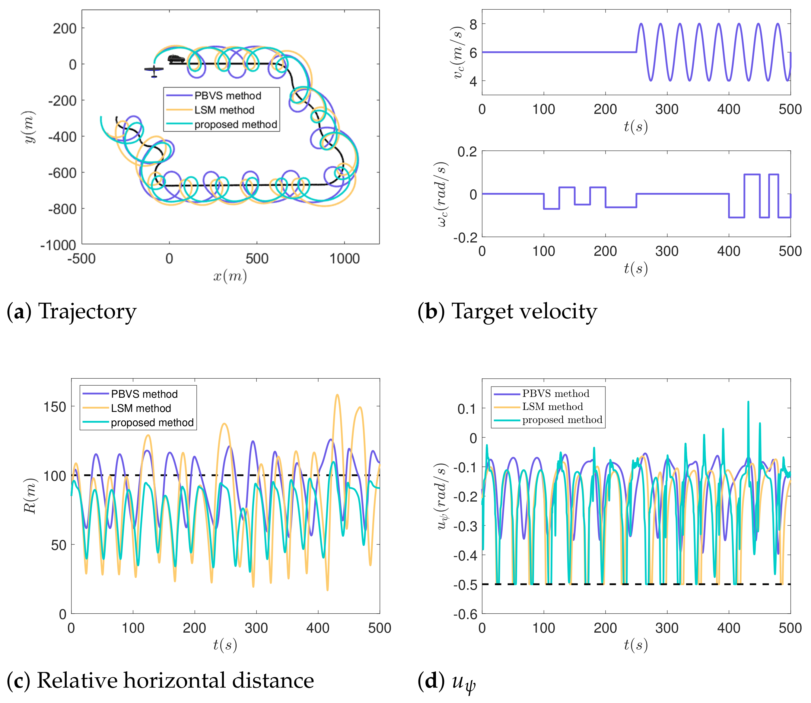
To further demonstrate the effectiveness of our method, a comparative simulation involving situations where the target executes complex movements is conducted. Specifically, we compare our proposed method with the PBVS method presented in [4] and the LSM method, and the corresponding results are depicted in Figure 6. The target’s speed and yaw rate are denoted by v c and ω c , respectively. Based on the trajectories illustrated in Figure 6a and the target velocity in Figure 6b, it is evident that the target’s motion is divided into four distinct phases as follows: (1) uniform linear motion at 0∼100 s; (2) uniform nonlinear motion at 100∼250 s; (3) linear motion at a changing speed at 250∼400 s; (4) nonlinear motion at a changing speed at 400∼500 s. Furthermore, Figure 6c displays the variation in the relative horizontal distance R between the UAV and the target. It is apparent that when employing the method in [4] and the LSM method, R frequently exceeds R m = 100 m, with the maximum of R reaching 124 m and 158 m, respectively. In comparison, our method effectively prevents R from exceeding R m , with only one instance occurring at about 430 s due to the rapid movement of the target and significant changes in its yaw. Even so, the maximum of R reaches just 109 m, which is smaller than that achieved by the other two methods. Additionally, the changes in the control inputs are depicted in Figure 6d. It is noticeable that the amplitude change of u ψ in our method exceeds that in the other two methods. This is beneficial in preventing R from exceeding R m , thereby enabling clear observation of the target.

5. HITL Simulations and Results

5.1. Simulation Setup

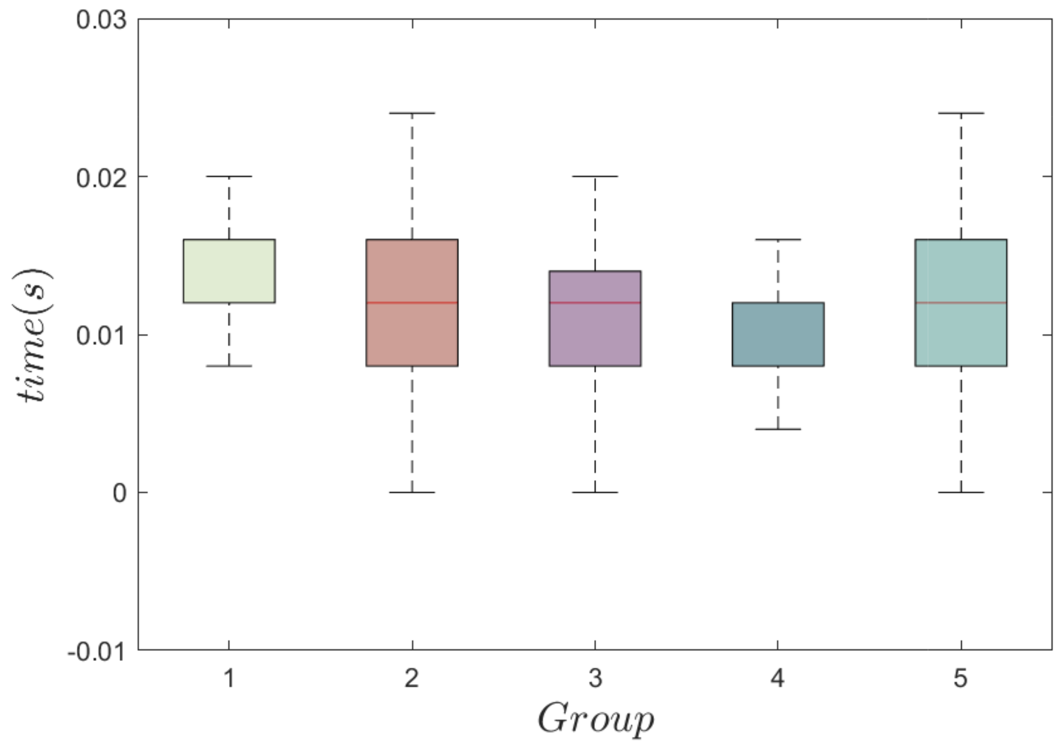
In order to achieve the practical application of the proposed method, a high-fidelity simulation system is built as shown Figure 7, which is based on the XTdrone [27] developed by our team. Note that we developed a full chain of verification from HITL simulation to flight test in the previous work [7,28], so that the program verified in the HITL simulation can be migrated to the physical platform directly, with just minor modifications in the interfaces. The simulation system is mainly composed of four parts: A jetson Xavier NX is adopted as the onboard processor with a robot operation system (ROS) installed, which is used for program deployment and provides interfaces to communicate with Gazebo; PX4 is a platform-agnostic autopilot software that communicates with ROS by MAVROS; QGroundControl (QGC) is a ground control station of PX4 that provides a visual interface to display the flight status and trajectory of the UAV; Gazebo is a 3D dynamic simulator and communicates with PX4 by MAVLink, where a black car represents the tracked target; the resolution of the pan-tilt camera is 1280 px × 720 px, and θ t [ 1.55 , 0.17 ] (unit: rad). The tiny version of YOLOv7 [29] is adopted in this work to achieve real-time and accurate detection with an average rate of 16 fps. The open-source nonlinear optimization solver NLopt is adopted to solve the MPC optimization problem; the computational time on the onboard processor is illustrated in Figure 8. Each group comprises 500 samples and the result demonstrates that the computational time is consistently below 0.025 s. This fulfills the real-time requirement. Figure 9 displays snapshots of the target tracking in different instants, which include the top views in Gazebo, the detected images with the target bounding box, and the trajectories in QGC. Note that the parameters used in the HITL simulations are the same as those in the numerical simulations.

5.2. Comparative Experiments of the LSM Method [7] and the Proposed Method

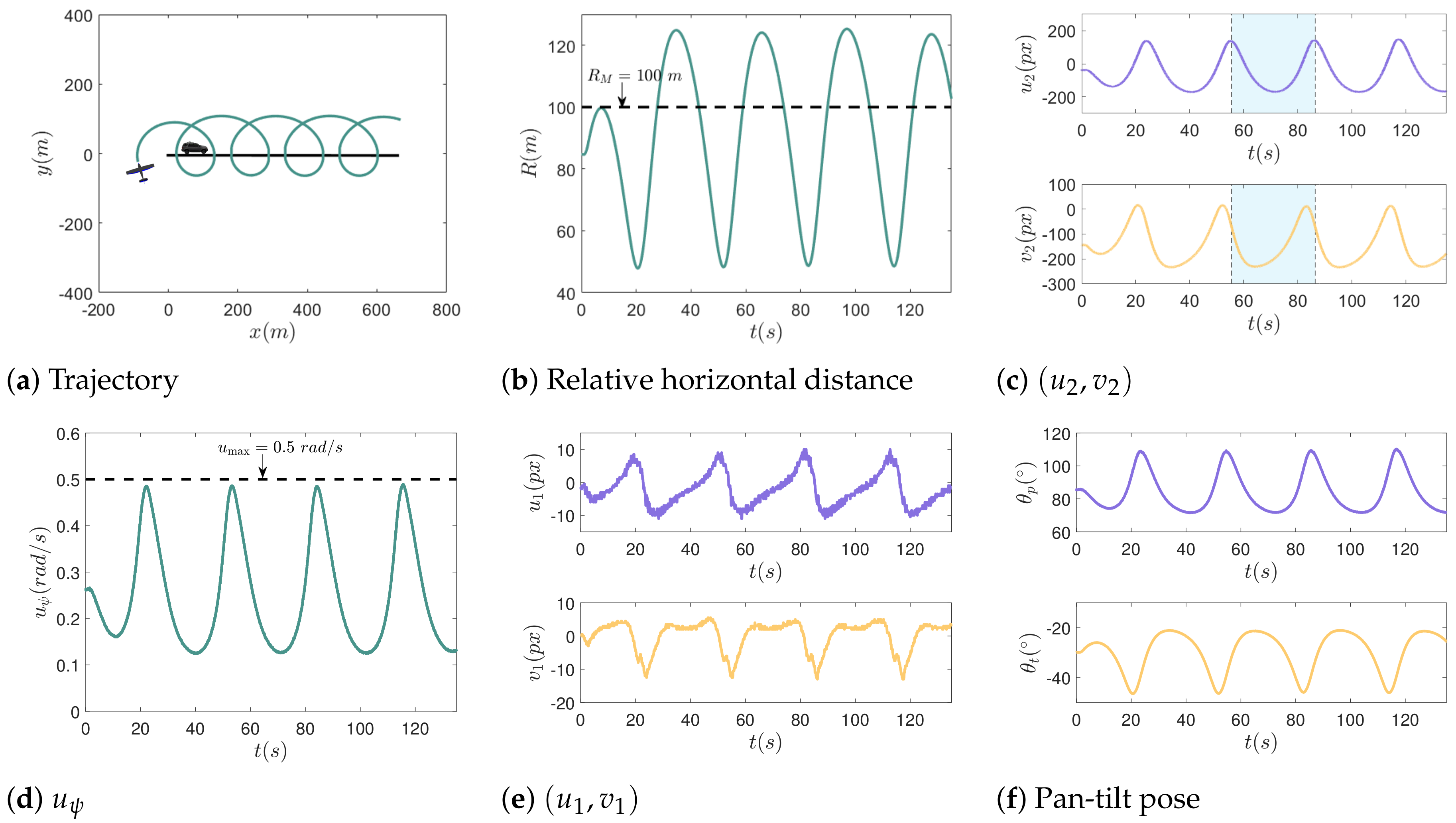
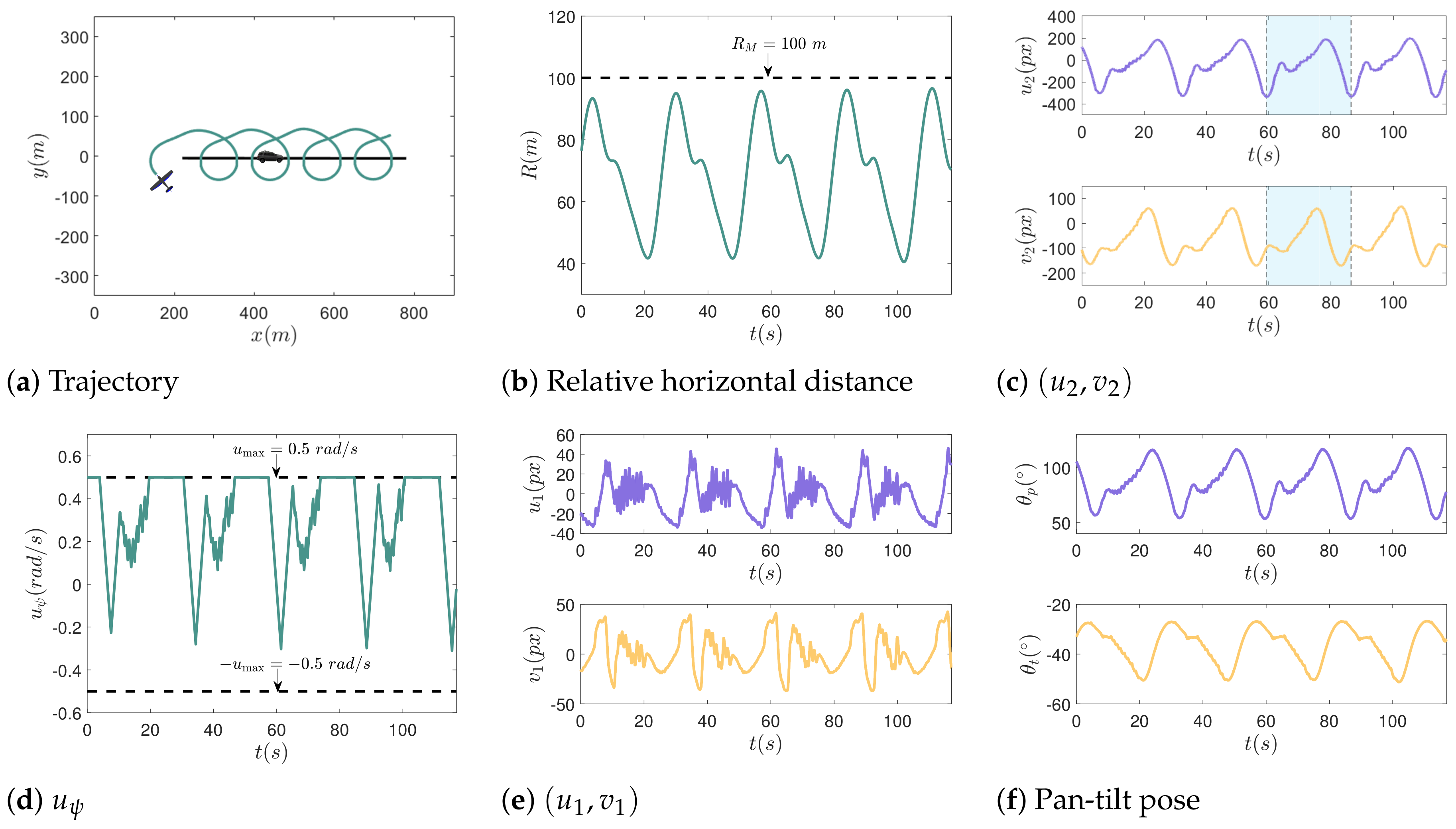
In the set of simulations, the tracking effects of the UAV for a moving target with V c = 5 m/s by the LSM method and the proposed method are compared; the simulation results are shown in Figure 10 and Figure 11, respectively. It can be observed that the maximum of R reaches 125 m in Figure 10b, which goes far beyond R M . However, R is less than R M throughout the tracking in Figure 11b. Moreover, the RMSE inside the blue zone shown in Figure 10b is RMSE ( L S M ) 203.33 , while that in Figure 11b is RMSE ( p r o ) 178.70 (unit: px), which decreases by 12.11%. The above results show the advantages of the proposed method over the LSM method.
The changes in ( u 1 , v 1 ) and the pose of the pan-tilt are presented as well. It can be observed that the curves in Figure 10e are smoother than those in Figure 11e. To account for the phenomenon, the change in u ψ needs to be taken into account. Since the change in u ψ in Figure 10d is smoother than that in Figure 11d, then the attitude change of the UAV in the former will be smoother as well, which leads to a small offset of the feature point in the image. Therefore, it can be found that the range of u 1 and v 1 are just about [−10, 10] and [−13, 5] (unit: px) in Figure 10e, while they are about [−32, 46] and [−36, 42] (unit: px) in Figure 11e, respectively. In this case, the feature point will return to the image center as long as the pan-tilt rotates smoothly in a small range; the comparison results are given in Figure 10f and Figure 11f, respectively. Even so, the feature point is still close to the image center with the proposed method.

5.3. Comparative Experiments of P 1 , s o f t and the Proposed Method

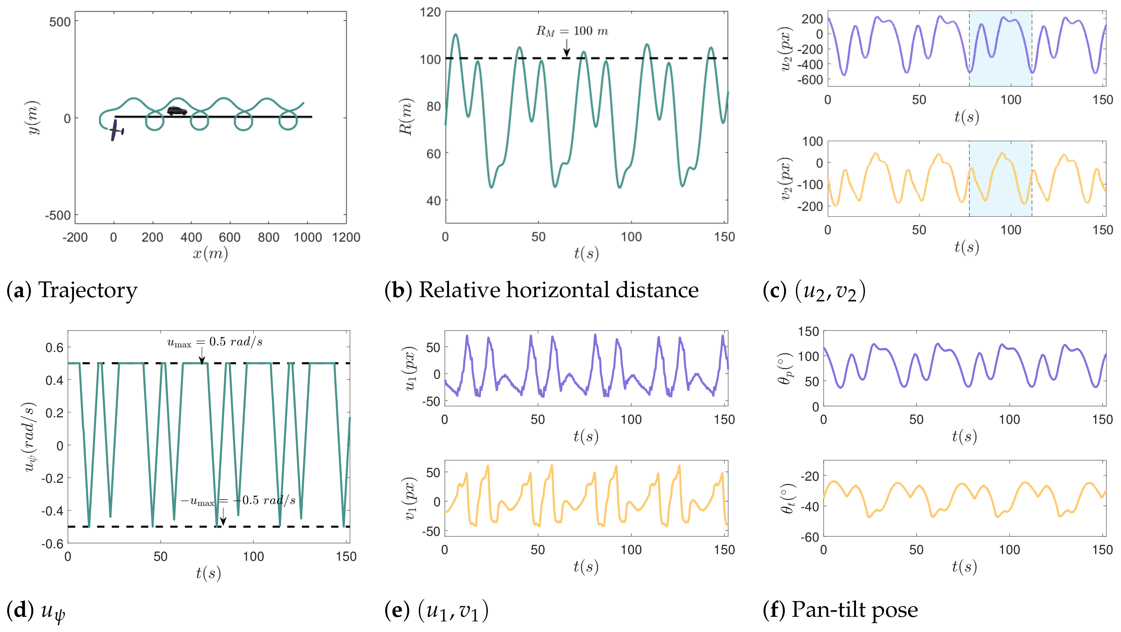
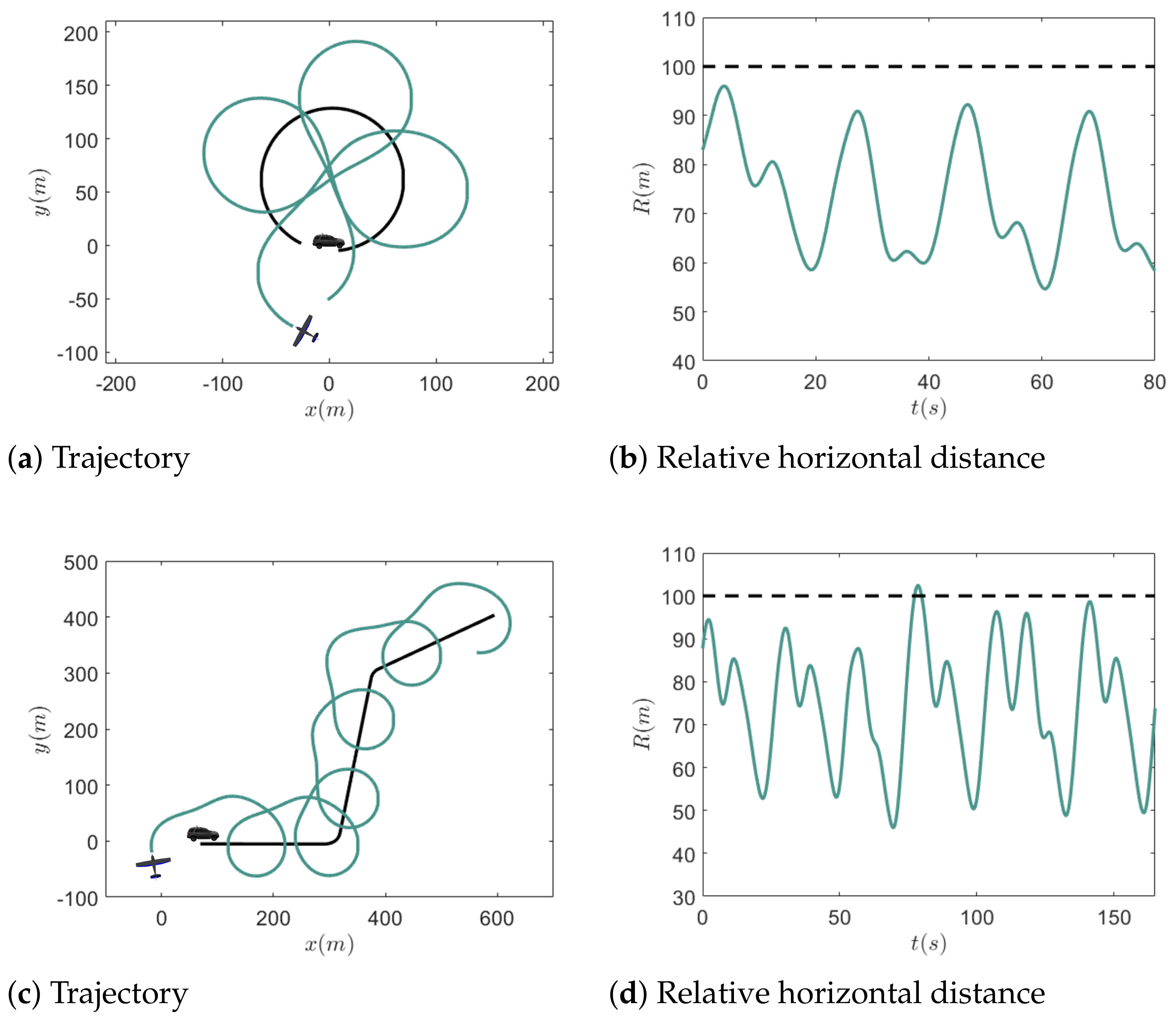
In the set of simulations, the tracking effects of the UAV for a moving target with V c = 7 m/s by P 1 , s o f t of (30) and the proposed method are compared; the corresponding results are shown in Figure 12 and Figure 13, respectively. It can be found in Figure 12b that when using the control input obtained from P 1 , s o f t , the maximum of R exceeds 120 m, and the average time that the target returns perception range ( R < R M ) is about 8.7 s. However, according to Figure 13b, the maximum of R does not exceed 110 m with the aid of the proposed method, and is even less than 105 m after 10 s, and the target will return to the perception range faster. Furthermore, the RMSE inside the blue zone shown in Figure 12c is about RMSE ( P 1 , s o f t ) 271.53 , while in Figure 13c is about RMSE ( p r o ) 258.17 (unit: px), which decreases by 4.9%. Compared with the results of numerical simulation in Section 4.2, it can be found that the changes in the RMSE are different. This is caused by two factors: one is the different target speed; the other is that there is a difference between the given speed and the real speed in the HITL simulation. Due to the second factor, the UAV is unable to achieve the expected motion to make the target remain in the perception range; then, R in both Figure 12b and Figure 13b exceeds R M . In comparison, R will soon drop below R M in Figure 13b, and then s 2 will approach s d to decrease the RMSE with the aid of the proposed method. Therefore, the RMSE in Figure 13b is smaller than that in Figure 12b. In terms of the change for u 1 and v 1 , it can be observed from Figure 12e and Figure 13e that their ranges are almost the same. Note that the sharp jitter of the curves is caused by the attitude change of the UAV and the time delay of the pan-tilt control. Figure 12f and Figure 13f present the changes in the pan-tilt.

5.4. Tracking Target with Nonlinear Motion

In the set of simulations, two typical nonlinear motions of the target are considered, including circular motion and sharp turns. The tracking results are shown as Figure 14, where the target moves at a speed of 5 m/s. According to Figure 14b, it is obvious that R is always less than R M . When the target moves in a sharp turn, it can be observed that R exceeds R M at about 80 s in Figure 14d. This is because the sharp turn of the target changes the relative movement trend between them, which leads to increase in R. Even so, the proposed method can make the target return to the perception range immediately within about 4 s. Based on the above simulations, the effectiveness of the proposed method is further verified.

6. Conclusions

In this paper, we have proposed an online MPC-based IBVS method for a fixed-wing UAV with a 2-DOF pan-tilt camera for target tracking. The method enables the UAV to achieve persistent tracking of the target, while concurrently maintaining the target near the image center. With the aid of MPC, the dynamic constraint of the UAV and the perception constraint of the camera can be considered when solving the optimization problem. After that, a soft constraint method is designed for practical implementation combined with a warm start.
Furthermore, a switching-based control strategy is proposed to return the target to the perception range quickly once it is outside the range, and the asymptotic stability for the controller is proven. Extensive comparative simulation experiments including numerical simulations and HITL simulations were conducted, which demonstrated the effectiveness and superiority of the proposed method. In the future, estimation of the target speed will be considered, and real flight tests will be conducted as well.

Author Contributions

Conceptualization, L.Y., X.W. and L.S.; methodology, L.Y. and Z.L.; software, L.Y.; validation, L.Y. and Y.Z.; formal analysis, L.Y.; investigation, L.Y. and X.W.; resources, X.W. and Z.L.; data curation, L.Y. and Y.Z.; writing—original draft preparation, L.Y.; writing—review and editing, X.W. and Z.L.; visualization, L.Y.; supervision, L.S.; project administration, X.W. and Z.L.; funding acquisition, Z.L. All authors have read and agreed to the published version of the manuscript.

Funding

This work was supported by the Natioanl Natural Science Fondation of China (61906209) and (61973309).

Data Availability Statement

The data presented in this study are available on request from the corresponding author.

Conflicts of Interest

The authors declare no conflict of interest.

References

  1. Chaumette, F.; Hutchinson, S. Visual servo control, part I: Basic approaches. IEEE Robot. Autom. Mag. 2006, 13, 82–90. [Google Scholar] [CrossRef]
  2. Li, Z.; Hovakimyan, N.; Dobrokhodov, V.; Kaminer, I. Vision-based target tracking and motion estimation using a small UAV. In Proceedings of the 49th IEEE Conference on Decision and Control (CDC), Atlanta, GA, USA, 15–17 December 2010; pp. 2505–2510. [Google Scholar]
  3. Choi, H.; Kim, Y. UAV guidance using a monocular-vision sensor for aerial target tracking. Control Eng. Pract. 2014, 22, 10–19. [Google Scholar] [CrossRef]
  4. Wang, X.; Zhu, H.; Zhang, D.; Zhou, D.; Wang, X. Vision-based detection and tracking of a mobile ground target using a fixed-wing UAV. Int. J. Adv. Robot. 2014, 11, 156. [Google Scholar] [CrossRef]
  5. Le Bras, F.; Hamel, T.; Mahony, R. Image-based visual servo control for circular trajectories for a fixed-wing aircraft. In Proceedings of the 48th IEEE Conference on Decision and Control (CDC) Held Jointly with 28th Chinese Control Conference (CCC), Shanghai, China, 16–18 December 2009; pp. 3430–3435. [Google Scholar]
  6. Peliti, P.; Rosa, L.; Oriolo, G.; Vendittelli, M. Vision-based loitering over a target for a fixed-wing UAV. In Proceedings of the 10th IFAC Symposium on Robot Control, Dubrovnik, Croatia, 5–7 September 2012; Volume 45, pp. 51–57. [Google Scholar]
  7. Yang, L.; Liu, Z.; Wang, X.; Yu, X.; Wang, G.; Shen, L. Image-based visual servo tracking control of a ground moving target for a fixed-wing unmanned aerial vehicle. J. Intell. Robot. Syst. 2021, 102, 1–20. [Google Scholar] [CrossRef]
  8. Triputra, F.R.; Trilaksono, B.R.; Adiono, T.; Sasongko, R.A. Visual servoing of fixed-wing unmanned aerial vehicle using command filtered backstepping. Int. J. Electr. Eng. Inform. 2015, 7, 9. [Google Scholar] [CrossRef]
  9. Ferreira, P.A.F.; Pinto, J.R.C. Visual based predictive control for a six degrees of freedom robot. In Proceedings of the 2006 IEEE Conference on Emerging Technologies and Factory Automation, Prague, Czech Republic, 20–22 September 2006; pp. 846–853. [Google Scholar]
  10. Allibert, G.; Courtial, E.; Chaumette, F. Predictive control for constrained image-based visual servoing. IEEE Trans. Robot. 2010, 26, 933–939. [Google Scholar] [CrossRef]
  11. Copot, C.; Lazar, C.; Burlacu, A. Predictive control of nonlinear visual servoing systems using image moments. IET Control Theory Appl. 2012, 6, 1486–1496. [Google Scholar] [CrossRef]
  12. Sauvée, M.; Poignet, P.; Dombre, E. Ultrasound image-based visual servoing of a surgical instrument through nonlinear model predictive control. Int. J. Robot. Res. 2008, 27, 25–40. [Google Scholar] [CrossRef]
  13. Hajiloo, A.; Keshmiri, M.; Xie, W.; Wang, T. Robust online model predictive control for a constrained image-based visual servoing. IEEE Trans. Ind. Electron. 2015, 63, 2242–2250. [Google Scholar]
  14. Gao, J.; Proctor, A.A.; Shi, Y.; Bradley, C. Hierarchical model predictive image-based visual servoing of underwater vehicles with adaptive neural network dynamic control. IEEE Trans. Cybern. 2015, 46, 2323–2334. [Google Scholar] [CrossRef] [PubMed]
  15. Mohamed, S.; Saraf, N.; Bernardini, D.; Goswami, D.; Basten, T.; Bemporad, A. Adaptive predictive control for pipelined multiprocessor image-based control systems considering workload variations. In Proceedings of the 2020 59th IEEE Conference on Decision and Control (CDC), Jeju, Republic of Korea, 14–18 December 2020; pp. 5236–5242. [Google Scholar]
  16. Qiu, Z.; Hu, S.; Liang, X. Disturbance observer based adaptive model predictive control for uncalibrated visual servoing in constrained environments. ISA Trans. 2020, 106, 40–50. [Google Scholar] [CrossRef] [PubMed]
  17. Liu, S.; Dong, J. Robust online model predictive control for image-based visual servoing in polar coordinates. Trans. Inst. Meas. Control 2020, 42, 890–903. [Google Scholar] [CrossRef]
  18. Liu, X.; Mao, J.; Yang, J.; Li, S.; Yang, K. Robust predictive visual servoing control for an inertially stabilized platform with uncertain kinematics. ISA Trans. 2021, 114, 347–358. [Google Scholar] [CrossRef] [PubMed]
  19. Sheng, H.; Shi, E.; Zhang, K. Image-based visual servoing of a quadrotor with improved visibility using model predictive control. In Proceedings of the 2019 IEEE 28th International Symposium on Industrial Electronics (ISIE), Vancouver, BC, Canada, 12–14 June 2019; pp. 551–556. [Google Scholar]
  20. Li, M.; Wu, H.; Liu, Z. Sampling-based path planning and model predictive image-based visual servoing for quadrotor UAVs. In Proceedings of the 2017 Chinese Automation Congress (CAC), Jinan, China, 20–22 October 2017; pp. 6237–6242. [Google Scholar]
  21. Zhang, K.; Shi, Y.; Sheng, H. Robust nonlinear model predictive control based visual servoing of quadrotor UAVs. IEEE ASME Trans. Mechatron. 2021, 26, 700–708. [Google Scholar] [CrossRef]
  22. Elfeky, M.; Elshafei, M.; Saif, A.W.A.; Malki, M.F.A. Modeling and simulation of quadrotor UAV with tilting rotors. Int. J. Control Autom. 2016, 14, 1047–1055. [Google Scholar] [CrossRef]
  23. Saif, A.W.A.; Aliyu, A.; Dhaifallah, M.A.; Elshafei, M. Decentralized backstepping control of a quadrotor with tilted-rotor under wind gusts. Int. J. Control Autom. 2018, 16, 2458–2472. [Google Scholar] [CrossRef]
  24. Sun, Z.; de Marina, H.G.; Seyboth, G.S.; Anderson, B.D.O.; Yu, C. Circular formation control of multiple unicycle-type agents with nonidentical constant speeds. IEEE Trans. Control Syst. Technol. 2018, 27, 192–205. [Google Scholar] [CrossRef]
  25. Zhao, S.; Wang, X.; Lin, Z.; Zhang, D.; Shen, L. Integrating vector field approach and input-to-state stability curved path following for unmanned aerial vehicles. IEEE Trans. Syst. Man Cybern. 2018, 50, 2897–2904. [Google Scholar] [CrossRef]
  26. Zhang, A.; Morari, M. Stability of model predictive control with soft constraints. In Proceedings of the 1994 33rd IEEE Conference on Decision and Control (CDC), Lake Buena Vista, FL, USA, 14–16 December 1994; pp. 1018–1023. [Google Scholar]
  27. Xiao, K.; Tan, S.; Wang, G.; An, X.; Wang, X.; Wang, X. XTDrone: A customizable multi-rotor UAVs simulation platform. In Proceedings of the 2020 4th International Conference on Robotics and Automation Sciences (ICRAS), Wuhan, China, 12–14 June 2020; pp. 55–61. [Google Scholar]
  28. Liu, Z.; Wang, X.; Shen, L.; Zhao, S.; Cong, Y.; Li, J.; Yin, D.; Jia, S.; Xiang, X. Mission-Oriented Miniature Fixed-Wing UAV Swarms: A Multilayered and Distributed Architecture. IEEE Trans. Syst. Man Cybern. 2020, 52, 1588–1602. [Google Scholar] [CrossRef]
  29. Wang, C.Y.; Bochkovskiy, A.; Liao, H.Y.M. YOLOv7: Trainable bag-of-freebies sets new state-of-the-art for real-time object detectors. In Proceedings of the 2023 IEEE/CVF Conference on Computer Vision and Pattern Recognition (CVPR), Vancouver, BC, Canada, 17–24 June 2023; pp. 7464–7475. [Google Scholar]
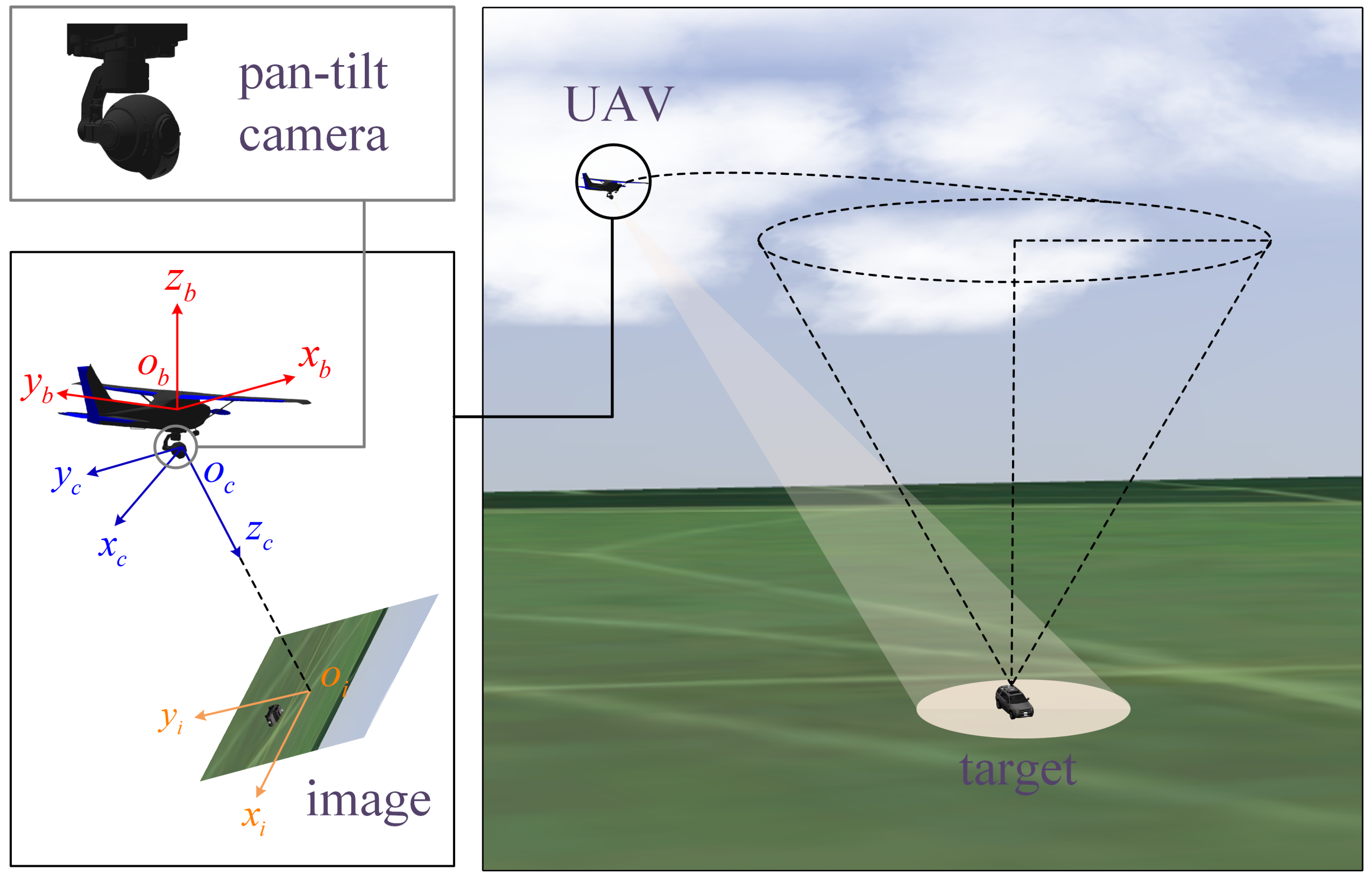
Figure 1. Target tracking for the fixed-wing UAV.
Drones 08 00136 g001
Figure 2. Schematic diagram of the pan-tilt camera.
Drones 08 00136 g002
Figure 3. The perception range of the UAV.
Drones 08 00136 g003
Figure 4. The simulation results when V c = 7 m/s.
Drones 08 00136 g004
Figure 5. The simulation results when V c = 9 m/s.
Drones 08 00136 g005
Figure 6. The simulation results when the target makes complex movements.
Drones 08 00136 g006
Figure 7. The HITL simulation setup.
Drones 08 00136 g007
Figure 8. The optimization time of our method on the onboard processor.
Drones 08 00136 g008
Figure 9. Snapshots of the target tracking in the HITL simulations.
Drones 08 00136 g009
Figure 10. The simulation results based on the LSM method when V c = 5 m/s.
Drones 08 00136 g010
Figure 11. The Simulation results based on the proposed method when V c = 5 m/s.
Drones 08 00136 g011
Figure 12. The simulation results based on P 1 , s o f t when V c = 7 m/s.
Drones 08 00136 g012
Figure 13. The simulation results based on the proposed method when V c = 7 m/s.
Drones 08 00136 g013
Figure 14. The simulation results when V c = 5 m/s. The target makes a circular motion in (a,b), while it makes a sharp turn in (c,d).
Drones 08 00136 g014
Table 1. Parameters and their values.
ParameterValueParameterValueParameterValue
V t 16 m/sH100 m R M 100 m
Δ R 10 m R d 50 m u max 0.5 rad/s
a max 0.02 rad/s Δ t 0.05 s Q s diag{0.5,2}
Q u 1.0 × 10 6 Q s , g diag{1,1} δ 0.99
β 1 1.0 × 10 4 β 2 1.0 × 10 3 β g 1.0 × 10 3
f537 N p 15 n max 100
Disclaimer/Publisher’s Note: The statements, opinions and data contained in all publications are solely those of the individual author(s) and contributor(s) and not of MDPI and/or the editor(s). MDPI and/or the editor(s) disclaim responsibility for any injury to people or property resulting from any ideas, methods, instructions or products referred to in the content.