Abstract
Today, ground control points (GCPs) represent indispensable tools for products’ georeferencing in all the techniques concerning remote sensing (RS), particularly in monitoring activities from unmanned aircraft system (UAS) platforms. This work introduces an innovative tool, smart GCPs, which combines different georeferencing procedures, offering a range of advantages. It can serve three fundamental purposes concurrently: (1) as a drone takeoff platform; (2) as a base station, allowing the acquisition of raw global navigation satellite system (GNSS) data for post-processed kinematic (PPK) surveys or by providing real-time GNSS corrections for precision positioning; (3) as a rover in the network real-time kinematic (NRTK) mode, establishing its position in real time with centimetric precision. The prototype has undergone testing in a dedicated study area, yielding good results for all three geodetic correction techniques: PPK, RTK, and GCP, achieving centimeter-level accuracy. Nowadays, this versatile prototype represents a unique external instrument, which is also easily transportable and able to connect to the GNSS RING network, obtaining real-time positioning corrections for a wide range of applications that require precise positioning. This capability is essential for environmental applications that require a multitemporal UAS-based study. When the real-time RING data are accessible to the scientific community operating in RS surveying, this work could be a helpful guide for researchers approaching such investigations.
1. Introduction
Today, unmanned aircraft systems (UASs) represent a common platform for mapping and performing the spatial analysis of territories [1,2,3]. Data collection through these technologies offers results in terms of quality and reliability comparable to those of conventional techniques (e.g., topographic campaigns, terrestrial laser scanning, and conventional aerial photogrammetry) [4,5,6], which require higher costs and very long times [7].
Over the last few years, various achievements and improvements in UASs have been made by numerous researchers from different disciplines. In fact, commercial societies, research institutes, and industries are interested in unmanned aerial vehicles (UAVs) as one of the simplest and cheapest pieces of equipment for data acquisition, which also depends on drones’ payloads.
Data acquired using UASs offer useful information for archaeological investigations and cataloging [8,9], geological and geomorphological surveys and monitoring [10,11,12,13,14,15], earthquake surface-faulting analyses [16], urban mapping [17], emergency assessments [18,19,20], land cover classifications [21,22,23], multitemporal investigations [24,25,26], and engineering applications [27,28]. Nowadays, most UASs include an onboard, multifrequency GNSS receiver, which is very useful for geomatic applications [29,30]. In fact, it is used to support navigation and for products’ georeferencing and three-dimensional (3D) positioning. To achieve high precision in 3D space when using remote-sensing techniques, it is necessary to use GCPs (ground control points) [31], and the number, accuracy, and distribution of GCPs in the investigated area [32,33,34] affect the precision of the geometric correction in remotely sensed imagery.
A precise georeferencing technique known as indirect georeferencing (IG) [35,36] consists of using GCPs to support assisted aerotriangulation (AAT) and reaches accuracies of a few centimeters, as evaluated using independent checkpoints (ICPs) [37]. The utilization of GCPs is the most accurate solution as it allows for the comparison of UAS images with those of any other remote-sensing product [38,39,40]. Following the IG approach, initially, images are georeferenced with the drone’s navigation coordinates and can be affected by metric errors, especially in the elevation component. Subsequently, point clouds are projected in an absolute coordinate system through a 3D linear similarity transformation taking into account the GCPs’ coordinates acquired during the survey. Using these steps, it is possible to obtain point clouds with great accuracy. However, the acquisition of terrestrial GCPs can be the main obstacle in some important applications of UASs, such as forest inventories and mapping and surveys in areas with steep slopes and susceptible to landslides, avalanches, and other potential risks [41].
An alternative georeferencing method for UAV images has recently emerged, namely, direct georeferencing (DG) [42,43], whereby control is provided by measuring digital image positions at exposure times with centimeter-level accuracy [44]. This method uses a UAS-mounted GNSS receiver, which is capable for supporting dual frequency, multiconstellation phase observations [45]. The use of an inertial measurement unit (IMU) and a GNSS for DG can result in quick data collection and a significant improvement in work efficiency, rendering DG less time-consuming and costly. Different authors have evaluated the accuracy of UAV-based DG methods with GNSS RTK/PPK technology, and the experimental results highlighted that horizontal and vertical RMSE values (root mean square error) [46,47] are on the order from centimeters to decimeters [48,49,50,51,52].
When carrying out a flight mission for photogrammetric purposes, there is a need to bring a lot of instrumentation into the field to obtain GNSS measurements. From these difficulties arose the need to build a portable and manageable instrument that contains as much functionality and instrumentation as possible.
This work describes and presents a smart GCP (S-GCP), implemented by the authors, with the following features: a multi-constellation/multi-band (L1, L2, and L5) GNSS receiver, Wi-Fi and Bluetooth connections, a 4G LTE router, and a power system with solar energy charging and a cooling mechanism.
This new tool is able to work with various configurations as follows:
- The S-GCP is used as takeoff and landing points for the drone;
- The S-GCP is used as a GNSS base to acquire raw GNSS data for the post-processing analysis (PPK survey);
- The S-GCP is used first to receive the real-time correction from CORS (specifically, RING networks, [53]) and then provide it to the drone (RTK survey);
- The S-GCP is used as a GNSS base to provide corrections to the rover in GCP measurements (GCP surveys).
In particular, in Section 3, “Experiments and Results”, the performance of the S-GCP set with configurations described in points 2, 3, and 4 are evaluated. The outcomes are examined separately and then compared to assess the accuracy of the instruments during a photogrammetric survey.
2. Materials and Methods
The tool proposed in this paper is assembled with equipment and materials already available at INGV. All the instrumentation is contained in a portable suitcase made up of two resealable solar panels; their size is 675 × 540 × 35 mm, and they work at a tension of 18 V and a maximum power of 50 Wp, as depicted in Figure 1.
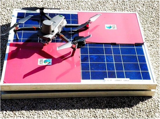
Figure 1.
Suitcase of smart GCP. The small back box is the GNSS antenna.
On the suitcase is installed a u-blox ANN-MB multiband (L1, L2/E5b/B2I) active GNSS antenna. Inside the suitcase are installed the components described below and presented in Figure 2.
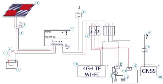
Figure 2.
S-GCP components’ connection: (1) solar panel; (2) power socket (DC max, 50 V); (3) power plug (DC max, 50 V); (4) unipolar switch; (5) disconnector with fuse holder; (6) solar battery (9 Ah, 12 V); (7) charge regulator; (8) RS485/ethernet interface; (9) disconnector with fuse holder; (10) RouterBoard (Mikrotik); (11) NO contact; (12) temperature control module; (13) voltmeter; (14) cooling fan; (15) temperature probe; (16) USB connector; (17) delay switch (30 s); (18) GNSS receiver; red lines indicate positive electrical cables, black lines indicate negative.
2.1. Power System
The power supply system of the S-GCP is standalone, consisting of a polycrystalline silicon photovoltaic module, a WRM15 charge regulator produced by Western Co. (San Benedetto del Tronto, Italy), and a hermetic lead–acid accumulator. The charge regulator is equipped with an MPPT charging circuit that can optimize the charge of the accumulators with any photovoltaic module that has a maximum power Voltage (Vmp) greater than the battery voltage and that falls within the open circuit Voltage limits (Voc) under 100 V. In addition, the system can also be recharged by means of a special 12 V DC power supply having a special power socket. The charge regulator is also equipped with an RS485 serial interface, thanks to which it is possible to set it and verify its operating status through the MODBUS communication protocol. The collected telemetry data can be consulted through the following:
- a web app interface, if the user is close to the S-GCP, through a Bluetooth connection (Figure 3a), ensuring the monitoring and the configuration of different parameters, including the produced power, load power, and battery charging;
 Figure 3. Real-time telemetry: (a) Bluetooth app for mobile devices where it is possible to visualize both the battery solar recharging and the S-GCP power consumption; (b) web portal that shows the battery voltage and the temperature inside the suitcase.
 - a web portal that can be accessed remotely, as illustrated in [54] (Figure 3b). Thanks to some Python queries that allow for storing, over time, information related to electrical parameters, such as the battery voltage, internal temperature, load current, photovoltaic current, photovoltaic voltage, and battery temperature.
2.2. GNSS Data Acquisition
The GNSS antenna is connected to an Emlid Reach M2 (https://emlid.com/reach/ accessed on 16 March 2024) GNSS receiver inside the S-GCP box. It is a multiband and multifrequency receiver that allows for precise UAS navigation and mapping. It provides robust performance and quick initialization, allowing for work on long baselines (e.g., a few tens of kilometers, [55]). The receiver has installed its web interface (Figure 4) to set different configurations and manage the collected data.
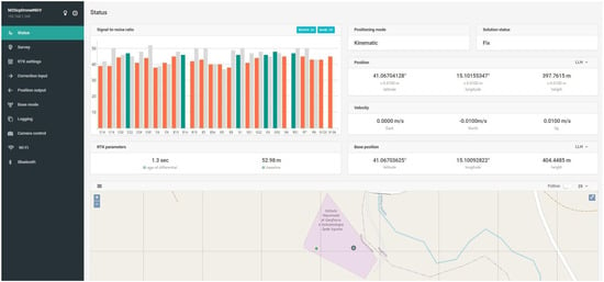
Figure 4.
GNSS ReachView web interface. On the left, there are various tools for the system’s settings; the central part displays a comprehensive overview of the GNSS’s status, which includes the number and SNR of satellites, the positioning mode, the solution status, and the accuracy and coordinates of both the base and rover and their locations on a map.
The user can visualize the interface by connecting via the Internet to the IP device address or via the ReachView smart app available for the Android and IOS operating systems.
2.3. Data Transmission
The S-GCP Internet connection is ensured by an LTE router consisting of a Mikrotik RouterBoard (RB912R-2nD-LTm) and a Mikrotik R11e-LTE modem.
The router, thanks to a secure SSTP VPN tunnel with the INGV Irpinia headquarters (http://www.irp.ingv.it accessed on 16 March 2024), allows the remote and real-time checking of the operating status of the instrumentation (i.e., the S-GCP and charge controller) and interaction with the relative configurations. Moreover, thanks to the VPN connection, if the smart GCP works in the NRTK (network real-time kinematic) mode, it can receive corrections via NTRIP (the networked transport of the RTCM via the internet protocol) from the stations of the National Integrated Network GNSS (RING—http://ring.gm.ingv.it accessed on 16 March 2024) collected by an NTRIP caster server (Figure 5). The implemented tool is the only platform capable for connecting and communicating (i.e., receiving corrections) with the GNSS RING network at the national level, even outside the INGV intranet systems. However, in the case of a lack of Internet connections, the acquired data can be collected and then corrected following the post-processing approach.
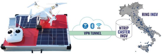
Figure 5.
Data transmission system illustrating the various types of connections between the RING network and the S-GCP prototype through the VPN tunnel.
3. Experiments and Results
3.1. Test Site, Reference Points, Ground Control Points, and Mission Planning
The test site corresponds to the parking lot of the INGV Irpinia headquarters. The area is mostly flat and paved and all around, small trees and light fixtures are distributed throughout. On the top of the building, the permanent station (GRO1) of the RING network is installed.
Initially, 15 reference points (RPs) were measured in the NRTK mode, as shown in Table 1. The antenna was set at 2.134 m on the ground. The acquisitions were performed using a rover (Emlid Reach RS2) connected through Wi-Fi to the S-GCP to receive corrections (RTCM3) from the mountpoint (GRO1) (with a very short baseline) of the NTRIP caster INGV.

Table 1.
Reference point (RP) measurements.
In addition, the positions of the other 30 ground control points (GCPs) were acquired to be used as control points during photogrammetric data processing (UAS-GCP survey, Section 3.3) and are summarized in Table 2.

Table 2.
Ground control point (GCP) measurements.
All the positions of the RPs and GCPs were acquired by fixing the carrier phase ambiguities [56] and RMS values within a few centimeters.
The aerial surveys were performed on 3 May 2023, using a DJI Phantom 4 RTK equipped with the RTK/PPK system. For each mission (i.e., PPK, RTK, and GCP surveys) the same flight plan was used (see Figure 6). The software employed for the mission planning is UgCS Enterprise version 4.16 (https://shop.ugcs.com/en-it accessed on 16 March 2024). With this software, the terrain-following module allows for the creation of missions by keeping the drone’s height from the ground constant. In particular, the tool Photogrammetry was used, and the parameters were set as follows: the flight altitude was 50 m above the ground for collecting nadiral images with a forward overlap of 80% and a side overlap of 70%, achieving an average ground sample distance (GSD) of 1 cm. The flight speed was 3.5 m/s, and the drone flew for 5.34 min, capturing 131 images and covering an area of 14,725 m2.
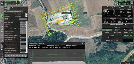
Figure 6.
UgCS Enterprise v. 4.20 software interface for UAS mission planning. In the left panel are shown the set parameters for the flight plan; the right panel shows the UAS telemetry, and the bottom window displays the survey’s altimetry and number of waypoints.
3.2. UAS-PPK Survey
In this approach, the UAS is set to acquire GNSS raw data at 10 Hz, and at the same time, for each photo, the corresponding triggers are recorded. These data will subsequently be used for image geotagging. Simultaneously, the GRO1 station was set for GNSS raw data acquisition at 10 Hz.
Photo geotagging is performed using RedToolbox v. 3.1 software (Figure 7—https://www.redcatch.at/redtoolbox/ accessed on 16 March 2024). First, you need to choose the GNSS data format and trigger used by the drone (DJI Phantom 4 RTK L1/L2) and then the format of the correct data output from the software (in this case, Agisoft project .psx, TextFile .txt, and Pdf Report .pdf files). Moreover, the choice of the output coordinate system is required, and in this case, the ellipsoidal model WGS84 was selected.

Figure 7.
RedToolbox interface: (a) device and output setting interface; (b) data loading and processing.
Successively, (i) the acquired photos, (ii) GNSS IMU and triggers and UAS data, and (iii) GNSS data of the base station (Figure 8b) were imported and processed with the RedToolbox environment. Regarding the position of the base station (GRO1), it was estimated, considering the information in the header of the RINEX file, to employ the same position in the RTK and GCP surveys. After the geotagging step, the corrected photos were processed following the SfM workflow [57,58] implemented in Agisoft Metashape Professional software (Version 2.03, Agisoft LLC, St. Petersburg, Russia), including image alignment, sparse point cloud generation, dense point cloud refinements, and DEM generation.
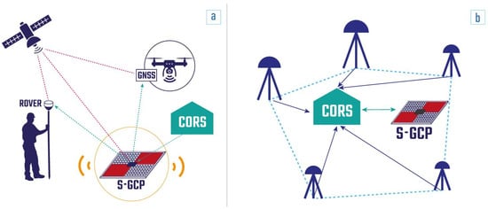
Figure 8.
(a) S-GCP in base/NTRIP configuration to provide real-time GNSS correction to rover and UAS; (b) S-GCP in rover/base configuration to receive real-time GNSS corrections from the CORS and save the raw data locally, using them later in PPK.
3.3. UAS-RTK Survey
In the second test, the UAS was connected to the S-GCP, gaining real-time RTCM3 correction (sampling at 1 Hz) from the GRO1 mountpoint via the NTRIP caster. With this configuration, the S-GCP plays a key role in ensuring the correct navigation to the drone in RTK, and, then, the geotagged images obtained the precise position in the adopted reference system (Figure 8a). Successively, the obtained imagery was processed with the same approach as that in the UAS-PPK survey.
3.4. UAS-GCP Survey
With this configuration, the UAS flight was performed without any position corrections, and, consequently, the geotags of the acquired images were affected by metric errors (The average errors for ‘X’, ‘Y’, and ‘Z’ were 2.19, 2.32, and 2.95 m, respectively.).
In the second step, during photogrammetric processing, the measured GCPs (Figure 8a) were recognized in each image and adopted for the point cloud optimization. In this way, we tried to refine the positions of the captured images by reducing the geotag metric errors to the centimeter scale.
3.5. Survey Results
In this section, the three digital elevation models (DEMs) obtained in various acquisition modes are introduced and subsequently compared. The 3 DEMs were obtained considering the same flight mission and the same number of images but with different geodetic correction approaches. So, the models are perfectly overlapping considering the planar coordinates.
In the GIS environment (Figure 9), the ellipsoidal elevation value was measured for each DEM at the same X and Y coordinates of the 15 RPs.
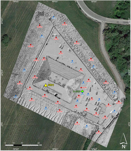
Figure 9.
PPK-survey DEM derived from the positions of the GCPs (red circles), RPs (blue circles), GRO1 RING station (yellow triangle), and S-GCP (green diamond).
Table 3 indicates the RPs’ elevations in meters a.s.l. (column 4), as measured with Emlid Reach RS2, and the projections of the elevations measured in the GIS environment onto the three obtained DEMs (columns 5, 7, and 9) corresponding to the same RP coordinates.

Table 3.
Survey result comparison.
Columns 6, 8, and 10 show the height differences (in meters) between the RPs and the 3 DEMs. It is interesting to note that for the DEM obtained through PPK processing, the elevation difference with respect to all the RPs never exceeds 3 cm.
Considering the DEM obtained with the RTK survey, the differences in the RPs range from 0.8 cm to 9.7 cm. Therefore, this DEM shows an error larger than that of the PPK-survey DEM. Lastly, the DEM produced with the use of GCPs seems to have the highest error rate. In fact, corresponding to RP4, the elevation difference is 13.6 cm, representing the highest value among the three DEMs. However, for the other RPs, the error is similar to that measured in the RTK survey.
Despite looking at the absolute value of the average difference, PPK processing produced the best result (1.7 cm), while the other two processing methods had errors similar to 3–4 cm.
The information in columns 6, 8, and 10 of Table 3 is depicted in Figure 10. As shown, only for some points, there are substantial differences, and they are located very close to the building and parking area.
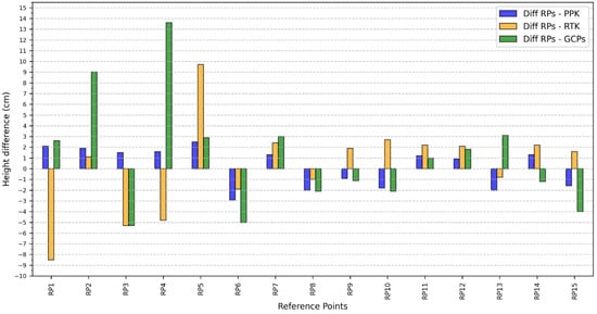
Figure 10.
Graphical comparison among the height differences (cm) of the three DEMs measured for the 15 RPs that were considered.
4. Discussion
New technological platforms for quick land surveying and measurements, such as UASs, are widespread in different fields, and the precise georeferencing of acquired data plays a key role in obtaining robust products. This study concerns the use of the S-GCP prototype by describing its application potential in high-precision georeferencing drone surveys. For this purpose, three DEM outcomes were compared, in terms of accuracy and error estimation, taking into account different survey approaches. Specifically, for the traditional UAS photogrammetric application, where the point cloud and all the resulting products are processed by georeferencing, the use of GCPs has been compared with that in the other two image orthorectification modes: PPK and RTK.
As shown in Section 3.4, the three different geodetic correction techniques constitute valid approaches for proximal remote sensing. Among them, PPK processing proved to be the most accurate as it showed the lowest average error, less than 2 cm, according to previous studies by Cirillo et al. (2022) and Martínez-Carricondo et al. (2023). This result was predictable because in PPK, the correction of the GNSS data can be refined in retrospect, adding more correct information, and because by working in RTK, the sample frequencies are lower. In fact, if the UAV in our test flew at 3.5 m/s and corrected its position at a frequency of 1 Hz, it obtained a correct position at every 3.5 m. From the drill, in PPK, we worked with a sampling frequency at 10 Hz, obtaining a new position at every 35 cm. The PPK method for georeferencing provides consistent accuracy and can take the place of the GCP-based method when it is challenging [59].
In the other two tests that were mentioned, the performance of the S-GCP proved to be highly promising also in scenarios where a nearby CORS system was unavailable. The vertical RMSE values achieved through RTK and GCP surveys may suffice for a broad range of medium-coarse mapping tasks, where extremely high-accuracy height models are not imperative. Specifically, in the RTK survey outlined in this study, the short baseline between the drone and the mountpoint (GRO1) significantly contributes to minimizing the RMSE. At the same time, when faced with the absence of a nearby and stable GNSS station, the S-GCP, leveraging its VPN connection to the RING network, has the potential to reduce the RMSE thanks to its capability to function as a station for obtaining position corrections.
The prototype presented herein is the only one that can work with the real-time data of the national GNSS INGV network, providing corrections to any connected device (terrestrial rover or drone). RING-INGV’s GNSS data are currently available a few hours after acquisition (ftp://gpsfree.gm.ingv.it accessed on 16 March 2024), with 30 s sampling. In the near future, INGV also plans to provide a real-time GNSS data distribution service with 1 Hz sampling.
GCP-derived DEMs are affected by higher diffuse errors that can be explained by the RMSE values in Table 2. In fact, despite the solution in the FIX mode, there are GCP positions acquired by Emlid Reach RS2 with different RMSEs, which may be because of problems in the ambiguity resolution processes. This survey was conducted on a flat surface without significant elevation gradients but with the presence of disturbing elements (buildings, walls, cars, and light poles). The higher errors corresponding to RPs were recorded in the crowded area, while for the other points (RP6-RP15), thanks to the absence of obstacles, the GCP-derived model could also be compared with the other two. From RP1 to RP5, the model derived from RTK also had the same behavior, while the model derived from PPK also demonstrated its effectiveness in the parking lot. S-GCP-based methods improve speed and allow photogrammetry to be used for a wider range of tasks in both industry and science by ensuring the required accuracy. Another strong point of S-GCP concerns its easy portability. In fact, in addition to the environmental conditions necessary for successful flights and scanning, such as the temperature, sun exposure, and humidity, the transportation of instrumentation to the field to have precise GNSS measurements may be an additional problem to be solved. Therefore, having a handy, easily transportable, and, at the same time, very reliable tool in terms of GNSS data management represents a further step forward for smart data acquisition surveys.
5. Conclusions
In this study, the potentialities of S-GCPs were evaluated during photogrammetric surveys, and, in particular, the contribution of S-GCPs to the correct geopositioning of acquired images has been assessed. The obtained DEMs have been compared, highlighting differences in terms of elevation errors corresponding to known reference points. In three distinct tests, the utilization of S-GCPs highlighted their potential across all the adopted photogrammetric approaches. Although the PPK method yielded the most precise DEM, both the GCP and RTK methods produced acceptable elevation models, demonstrating the effectiveness of S-GCPs in enhancing accuracy thanks to their capability to obtain corrections from private and public GNSS CORS stations (specifically, in the RING network).
In conclusion, the use of S-GCPs allows for connecting drones to different stations in the RING network, and, therefore, their use can be a replicable added value throughout the Italian national territory. Furthermore, there are RING stations located in other areas of the Mediterranean Basin (e.g., Malta and Greece), allowing for the use of S-GCPs outside of Italy.
The RING network represents a scientifically driven permanent GNSS infrastructure, and the capability of S-GCPs to connect to it constitutes an added value of this tool, especially in the reconstruction of differential DEMs along a certain time span: for this application, having a stable station within a CORS plays a key role.
With regard to the encouraging results that were achieved, the S-GCP prototype can be used for several data acquisition campaigns involving the use of drones and where high precision in the georeferencing of the acquired data is required, such as lidar, echo-sounding, and ground-penetrating radar.
In addition, the S-GCP prototype can be used in other geodesy applications: for example, it can be used as a GNSS mobile station for “noise tests” that are carried out at sites where the GNSS station of a permanent network is to be installed. S-GCPs would significantly reduce the amount of equipment to be transported and installed, making both telemetry and GNSS data usable in real time and allowing for instant “quality checks” of the same.
The authors, in the next few months, will start the procedure to obtain the patent of the prototype, and in the future, substantial changes can be made to the tool presented in this article by optimizing the size and components.
Author Contributions
Conceptualization, N.A.F.; methodology, N.A.F.; validation, N.A.F., P.M., A.M., L.F., A.C., R.M. (Raffaele Moschillo), C.G., R.M. (Robert Migliazza), G.S. and A.V.; formal analysis, N.A.F., P.M., A.M., L.F., A.C., R.M. (Raffaele Moschillo), C.G., R.M. (Robert Migliazza), G.S. and A.V.; investigation, N.A.F., P.M., A.M., L.F., A.C., R.M. (Raffaele Moschillo), C.G., R.M. (Robert Migliazza), G.S. and A.V.; resources, N.A.F., P.M., A.M., L.F., A.C., R.M. (Raffaele Moschillo), C.G., R.M. (Robert Migliazza), G.S. and A.V.; data curation, N.A.F.; writing—original draft preparation, N.A.F., P.M., A.M., L.F., A.C., R.M. (Raffaele Moschillo), C.G., R.M. (Robert Migliazza), G.S. and A.V.; writing—review and editing, N.A.F., P.M., A.M., L.F., A.C., R.M. (Raffaele Moschillo), C.G., R.M. (Robert Migliazza), G.S. and A.V.; visualization, N.A.F., P.M., A.M., L.F., A.C., R.M. (Raffaele Moschillo), C.G., R.M. (Robert Migliazza), G.S. and A.V.; supervision, N.A.F.; project administration, N.A.F. All authors have read and agreed to the published version of the manuscript.
Funding
This research received no external funding.
Acknowledgments
The authors would like to thank the RING infrastructure for providing the GNSS data and the technology lab at INGV Irpinia headquarters for having supplied the materials used for the assembly of the prototype that is presented.
Conflicts of Interest
The authors declare no conflicts of interest.
References
- Rakha, T.; Gorodetsky, A. Review of Unmanned Aerial System (UAS) Applications in the Built Environment: Towards Automated Building Inspection Procedures Using Drones. Autom. Constr. 2018, 93, 252–264. [Google Scholar] [CrossRef]
- Kerle, N.; Nex, F.; Gerke, M.; Duarte, D.; Vetrivel, A. UAV-Based Structural Damage Mapping: A Review. ISPRS Int. J. Geo-Inf. 2020, 9, 14. [Google Scholar] [CrossRef]
- Sigala, A.; Langhals, B. Applications of Unmanned Aerial Systems (UAS): A Delphi Study Projecting Future UAS Missions and Relevant Challenges. Drones 2020, 4, 8. [Google Scholar] [CrossRef]
- Colomina, I.; Molina, P. Unmanned Aerial Systems for Photogrammetry and Remote Sensing: A Review. ISPRS J. Photogramm. Remote Sens. 2014, 92, 79–97. [Google Scholar] [CrossRef]
- Pepe, M.; Fregonese, L.; Scaioni, M. Planning Airborne Photogrammetry and Remote-Sensing Missions with Modern Platforms and Sensors. Eur. J. Remote Sens. 2018, 51, 412–436. [Google Scholar] [CrossRef]
- Jiang, S.; Jiang, W.; Wang, L. Unmanned Aerial Vehicle-Based Photogrammetric 3D Mapping: A Survey of Techniques, Applications, and Challenges. IEEE Geosci. Remote Sens. Mag. 2022, 10, 135–171. [Google Scholar] [CrossRef]
- Grubesic, T.H.; Nelson, J.R. UAS Platforms and Applications for Mapping and Urban Analysis. In UAVs and Urban Spatial Analysis: An Introduction; Grubesic, T.H., Nelson, J.R., Eds.; Springer International Publishing: Cham, Switzerland, 2020; pp. 13–29. ISBN 978-3-030-35865-5. [Google Scholar]
- Campana, S. Drones in Archaeology. State-of-the-Art and Future Perspectives. Archaeol. Prospect. 2017, 24, 275–296. [Google Scholar] [CrossRef]
- Adamopoulos, E.; Rinaudo, F. UAS-Based Archaeological Remote Sensing: Review, Meta-Analysis and State-of-the-Art. Drones 2020, 4, 46. [Google Scholar] [CrossRef]
- Saito, H.; Uchiyama, S.; Hayakawa, Y.S.; Obanawa, H. Landslides Triggered by an Earthquake and Heavy Rainfalls at Aso Volcano, Japan, Detected by UAS and SfM-MVS Photogrammetry. Prog. Earth Planet. Sci 2018, 5, 15. [Google Scholar] [CrossRef]
- Heincke, B.; Jackisch, R.; Saartenoja, A.; Salmirinne, H.; Rapp, S.; Zimmermann, R.; Pirttijärvi, M.; Sörensen, E.V.; Gloaguen, R.; Ek, L.; et al. Developing Multi-Sensor Drones for Geological Mapping and Mineral Exploration: Setup and First Results from the MULSEDRO Project. GEUS Bull. 2019, 43. [Google Scholar] [CrossRef]
- Hamshaw, S.D.; Engel, T.; Rizzo, D.M.; O’Neil-Dunne, J.; Dewoolkar, M.M. Application of Unmanned Aircraft System (UAS) for Monitoring Bank Erosion along River Corridors. Geomat. Nat. Hazards Risk 2019, 10, 1285–1305. [Google Scholar] [CrossRef]
- Yang, Q.; Tang, F.; Wang, F.; Tang, J.; Fan, Z.; Ma, T.; Su, Y.; Xue, J. A New Technical Pathway for Extracting High Accuracy Surface Deformation Information in Coal Mining Areas Using UAV LiDAR Data: An Example from the Yushen Mining Area in Western China. Measurement 2023, 218, 113220. [Google Scholar] [CrossRef]
- Koukouvelas, I.K.; Caputo, R.; Nikolakopoulos, K.G.; Kyriou, A.; Famiglietti, N.A. Is the Mesochori Fault a Key Structure for Understanding the Earthquake Activity during the 2021 Damasi Earthquakes in Northern Thessaly, Greece? Geosciences 2023, 13, 331. [Google Scholar] [CrossRef]
- Cirillo, D.; Zappa, M.; Tangari, A.C.; Brozzetti, F.; Ietto, F. Rockfall Analysis from UAV-Based Photogrammetry and 3D Models of a Cliff Area. Drones 2024, 8, 31. [Google Scholar] [CrossRef]
- Menichetti, M.; Roccheggiani, M.; De Guidi, G.; Carnemolla, F.; Brighenti, F.; Barreca, G.; Monaco, C. Sentinel-1 Interferometry and UAV Aerial Survey for Mapping Coseismic Ruptures: Mts. Sibillini vs. Mt. Etna Volcano. Remote Sens. 2023, 15, 2514. [Google Scholar] [CrossRef]
- Salas López, R.; Terrones Murga, R.E.; Silva-López, J.O.; Rojas-Briceño, N.B.; Gómez Fernández, D.; Oliva-Cruz, M.; Taddia, Y. Accuracy Assessment of Direct Georeferencing for Photogrammetric Applications Based on UAS-GNSS for High Andean Urban Environments. Drones 2022, 6, 388. [Google Scholar] [CrossRef]
- Ameri, B.; Meger, D.; Power, K.; Gao, D.Y. UAS Applications: Disaster & Emergency Management. In Proceedings of the ASPRS 2009 Annual Conference, Baltimore, MD, USA, 9–13 March 2009. [Google Scholar]
- Xu, Z.; Yang, J.; Peng, C.; Wu, Y.; Jiang, X.; Li, R.; Zheng, Y.; Gao, Y.; Liu, S.; Tian, B. Development of an UAS for Post-Earthquake Disaster Surveying and Its Application in Ms7.0 Lushan Earthquake, Sichuan, China. Comput. Geosci. 2014, 68, 22–30. [Google Scholar] [CrossRef]
- Mandirola, M.; Casarotti, C.; Peloso, S.; Lanese, I.; Brunesi, E.; Senaldi, I.; Risi, F.; Monti, A.; Facchetti, C. Guidelines for the Use of Unmanned Aerial Systems for Fast Photogrammetry-Oriented Mapping in Emergency Response Scenarios. Int. J. Disaster Risk Reduct. 2021, 58, 102207. [Google Scholar] [CrossRef]
- Hassler, S.C.; Baysal-Gurel, F. Unmanned Aircraft System (UAS) Technology and Applications in Agriculture. Agronomy 2019, 9, 618. [Google Scholar] [CrossRef]
- White, C.T.; Petrasova, A.; Reckling, W.; Mitasova, H. Automated Land Cover Change Detection through Rapid UAS Updates of Digital Surface Models. Int. Arch. Photogramm. Remote Sens. Spat. Inf. Sci. 2020, XLII-3-W11, 155–159. [Google Scholar] [CrossRef]
- Belcore, E.; Piras, M.; Pezzoli, A. Land Cover Classification from Very High-Resolution UAS Data for Flood Risk Mapping. Sensors 2022, 22, 5622. [Google Scholar] [CrossRef]
- Civico, R.; Ricci, T.; Scarlato, P.; Andronico, D.; Cantarero, M.; Carr, B.B.; De Beni, E.; Del Bello, E.; Johnson, J.B.; Kueppers, U.; et al. Unoccupied Aircraft Systems (UASs) Reveal the Morphological Changes at Stromboli Volcano (Italy) before, between, and after the 3 July and 28 August 2019 Paroxysmal Eruptions. Remote Sens. 2021, 13, 2870. [Google Scholar] [CrossRef]
- Martínez, C.; Grez, P.W.; Martín, R.A.; Acuña, C.E.; Torres, I.; Contreras-López, M. Coastal Erosion in Sandy Beaches along a Tectonically Active Coast: The Chile Study Case. Prog. Phys. Geogr. Earth Environ. 2022, 46, 250–271. [Google Scholar] [CrossRef]
- Massaro, L.; Forte, G.; De Falco, M.; Santo, A. Geomorphological Evolution of Volcanic Cliffs in Coastal Areas: The Case of Maronti Bay (Ischia Island). Geosciences 2023, 13, 313. [Google Scholar] [CrossRef]
- Griffiths, D.; Boehm, J. Rapid object detection systems, utilising deep learning and unmanned aerial systems (uas) for civil engineering applications. Int. Arch. Photogramm. Remote Sens. Spat. Inf. Sci. 2018, XLII–2, 391–398. [Google Scholar] [CrossRef]
- Wang, X.; Demartino, C.; Narazaki, Y.; Monti, G.; Spencer, B.F. Rapid Seismic Risk Assessment of Bridges Using UAV Aerial Photogrammetry. Eng. Struct. 2023, 279, 115589. [Google Scholar] [CrossRef]
- Sun, H.; Li, L.; Ding, X.; Guo, B. The Precise Multimode GNSS Positioning for UAV and Its Application in Large Scale Photogrammetry. Geo-Spat. Inf. Sci. 2016, 19, 188–194. [Google Scholar] [CrossRef]
- Stöcker, C.; Nex, F.; Koeva, M.; Gerke, M. Quality Assessment of Combined IMU/GNSS Data for Direct Georeferencing in the Context of UAV-Based Mapping. Int. Arch. Photogramm. Remote Sens. Spat. Inf. Sci. 2017, XLII-2-W6, 355–361. [Google Scholar] [CrossRef]
- Xiang, H.; Tian, L. Method for Automatic Georeferencing Aerial Remote Sensing (RS) Images from an Unmanned Aerial Vehicle (UAV) Platform. Biosyst. Eng. 2011, 108, 104–113. [Google Scholar] [CrossRef]
- Wangfei, Z.; Jianguo, G.; Tianshu, X.; Yanru, H. The Selection of Ground Control Points in a Remote Sensing Image Correction Based on Weighted Voronoi Diagram. In Proceedings of the 2009 International Conference on Information Technology and Computer Science, Kiev, Ukraine, 25–26 July 2009; Volume 2, pp. 326–329. [Google Scholar]
- Guang, Y.; Weili, J. Research on Impact of Ground Control Point Distribution on Image Geometric Rectification Based on Voronoi Diagram. Procedia Environ. Sci. 2011, 11, 365–371. [Google Scholar] [CrossRef]
- Villanueva, J.K.S.; Blanco, A.C. Optimization of ground control point (GCP) configuration for unmanned aerial vehicle (uav) survey using structure from motion (SFM). Int. Arch. Photogramm. Remote Sens. Spat. Inf. Sci. 2019, XLII-4-W12, 167–174. [Google Scholar] [CrossRef]
- dos Santos, D.R.; Dal Poz, A.P.; Khoshelham, K. Indirect Georeferencing of Terrestrial Laser Scanning Data using Control Lines. Photogramm. Rec. 2013, 28, 276–292. [Google Scholar] [CrossRef]
- Jaud, M.; Letortu, P.; Augereau, E.; Le Dantec, N.; Beauverger, M.; Cuq, V.; Prunier, C.; Le Bivic, R.; Delacourt, C. Adequacy of Pseudo-Direct Georeferencing of Terrestrial Laser Scanning Data for Coastal Landscape Surveying against Indirect Georeferencing. Eur. J. Remote Sens. 2017, 50, 155–165. [Google Scholar] [CrossRef]
- Benjamin, A.R.; O’Brien, D.; Barnes, G.; Wilkinson, B.E.; Volkmann, W. Improving Data Acquisition Efficiency: Systematic Accuracy Evaluation of GNSS-Assisted Aerial Triangulation in UAS Operations. J. Surv. Eng. 2020, 146, 05019006. [Google Scholar] [CrossRef]
- Sanz-Ablanedo, E.; Chandler, J.H.; Rodríguez-Pérez, J.R.; Ordóñez, C. Accuracy of Unmanned Aerial Vehicle (UAV) and SfM Photogrammetry Survey as a Function of the Number and Location of Ground Control Points Used. Remote Sens. 2018, 10, 1606. [Google Scholar] [CrossRef]
- Meinen, B.U.; Robinson, D.T. Mapping Erosion and Deposition in an Agricultural Landscape: Optimization of UAV Image Acquisition Schemes for SfM-MVS. Remote Sens. Environ. 2020, 239, 111666. [Google Scholar] [CrossRef]
- Liu, X.; Lian, X.; Yang, W.; Wang, F.; Han, Y.; Zhang, Y. Accuracy Assessment of a UAV Direct Georeferencing Method and Impact of the Configuration of Ground Control Points. Drones 2022, 6, 30. [Google Scholar] [CrossRef]
- Tomaštík, J.; Mokroš, M.; Surový, P.; Grznárová, A.; Merganič, J. UAV RTK/PPK Method—An Optimal Solution for Mapping Inaccessible Forested Areas? Remote Sens. 2019, 11, 721. [Google Scholar] [CrossRef]
- Turner, D.; Lucieer, A.; Wallace, L. Direct Georeferencing of Ultrahigh-Resolution UAV Imagery. IEEE Trans. Geosci. Remote Sens. 2014, 52, 2738–2745. [Google Scholar] [CrossRef]
- Gabrlik, P.; la Cour-Harbo, A.; Kalvodova, P.; Zalud, L.; Janata, P. Calibration and Accuracy Assessment in a Direct Georeferencing System for UAS Photogrammetry. Int. J. Remote Sens. 2018, 39, 4931–4959. [Google Scholar] [CrossRef]
- Chris, M.; Edward, M.; James, S. Manual of Photogrammetry; ASPRS: Bethesda, MD, USA, 2004. [Google Scholar]
- Stott, E.; Williams, R.D.; Hoey, T.B. Ground Control Point Distribution for Accurate Kilometre-Scale Topographic Mapping Using an RTK-GNSS Unmanned Aerial Vehicle and SfM Photogrammetry. Drones 2020, 4, 55. [Google Scholar] [CrossRef]
- Li, X.; Ge, M.; Dai, X.; Ren, X.; Fritsche, M.; Wickert, J.; Schuh, H. Accuracy and Reliability of Multi-GNSS Real-Time Precise Positioning: GPS, GLONASS, BeiDou, and Galileo. J. Geod. 2015, 89, 607–635. [Google Scholar] [CrossRef]
- Famiglietti, N.A.; Cecere, G.; Grasso, C.; Memmolo, A.; Vicari, A. A Test on the Potential of a Low Cost Unmanned Aerial Vehicle RTK/PPK Solution for Precision Positioning. Sensors 2021, 21, 3882. [Google Scholar] [CrossRef]
- Lo, C.F.; Tsai, M.L.; Chiang, K.W.; Chu, C.H.; Tsai, G.J.; Cheng, C.K.; El-Sheimy, N.; Ayman, H. The direct georeferencing application and performance analysis of uav helicopter in gcp-free area. Int. Arch. Photogramm. Remote Sens. Spat. Inf. Sci. 2015, XL-1-W4, 151–157. [Google Scholar] [CrossRef]
- Shahbazi, M.; Sohn, G.; Théau, J.; Menard, P. Development and Evaluation of a UAV-Photogrammetry System for Precise 3D Environmental Modeling. Sensors 2015, 15, 27493–27524. [Google Scholar] [CrossRef]
- Padró, J.-C.; Muñoz, F.-J.; Planas, J.; Pons, X. Comparison of Four UAV Georeferencing Methods for Environmental Monitoring Purposes Focusing on the Combined Use with Airborne and Satellite Remote Sensing Platforms. Int. J. Appl. Earth Obs. Geoinf. 2019, 75, 130–140. [Google Scholar] [CrossRef]
- Cirillo, D.; Cerritelli, F.; Agostini, S.; Bello, S.; Lavecchia, G.; Brozzetti, F. Integrating Post-Processing Kinematic (PPK)–Structure-from-Motion (SfM) with Unmanned Aerial Vehicle (UAV) Photogrammetry and Digital Field Mapping for Structural Geological Analysis. ISPRS Int. J. Geo-Inf. 2022, 11, 437. [Google Scholar] [CrossRef]
- Martínez-Carricondo, P.; Agüera-Vega, F.; Carvajal-Ramírez, F. Accuracy Assessment of RTK/PPK UAV-Photogrammetry Projects Using Differential Corrections from Multiple GNSS Fixed Base Stations. Geocarto Int. 2023, 38, 2197507. [Google Scholar] [CrossRef]
- Avallone, A.; Selvaggi, G.; D’Anastasio, E.; D’Agostino, N.; Pietrantonio, G.; Riguzzi, F.; Serpelloni, E.; Anzidei, M.; Casula, G.; Cecere, G.; et al. The RING Network: Improvements to a GPS Velocity Field in the Central Mediterranean. Ann. Geophys. 2010, 53, 2. [Google Scholar] [CrossRef]
- Castagnozzi, A.; Falco, L.; Cogliano, R. Upgrade del sistema di alimentazione delle stazioni sismiche/GPS e monitoraggio remoto dei parametri elettrici. Rapp. Tec. 2018. [Google Scholar] [CrossRef]
- Takasu, T.; Yasuda, A. Kalman-Filter-Based Integer Ambiguity Resolution Strategy for Long-Baseline RTK with Ionosphere and Troposphere Estimation. In Proceedings of the 23rd International Technical Meeting of the Satellite Division of the Institute of Navigation (ION GNSS 2010), Portland, OR, USA, 24 September 2010; pp. 161–171. [Google Scholar]
- Laoniphon, C.; Thongtan, T.; Satirapod, C. Performance Assessments of Correction Models in GNSS Network-Based RTK Positioning. In Proceedings of the 2021 18th International Conference on Electrical Engineering/Electronics, Computer, Telecommunications and Information Technology (ECTI-CON), Chiang Mai, Thailand, 19–22 May 2021; pp. 2–5. [Google Scholar]
- Rosnell, T.; Honkavaara, E. Point Cloud Generation from Aerial Image Data Acquired by a Quadrocopter Type Micro Unmanned Aerial Vehicle and a Digital Still Camera. Sensors 2012, 12, 453–480. [Google Scholar] [CrossRef] [PubMed]
- Smith, M.W.; Carrivick, J.L.; Quincey, D.J. Structure from Motion Photogrammetry in Physical Geography. Prog. Phys. Geogr. Earth Environ. 2016, 40, 247–275. [Google Scholar] [CrossRef]
- McMahon, C.; Mora, O.E.; Starek, M.J. Evaluating the Performance of sUAS Photogrammetry with PPK Positioning for Infrastructure Mapping. Drones 2021, 5, 50. [Google Scholar] [CrossRef]
Disclaimer/Publisher’s Note: The statements, opinions and data contained in all publications are solely those of the individual author(s) and contributor(s) and not of MDPI and/or the editor(s). MDPI and/or the editor(s) disclaim responsibility for any injury to people or property resulting from any ideas, methods, instructions or products referred to in the content. |
© 2024 by the authors. Licensee MDPI, Basel, Switzerland. This article is an open access article distributed under the terms and conditions of the Creative Commons Attribution (CC BY) license (https://creativecommons.org/licenses/by/4.0/).