1. Introduction
UAVs have rapidly emerged as multipurpose indispensable tools in our modern era, bringing significant innovations in a variety of fields [
1,
2,
3]. One of the sectors where UAVs have found an appealing application is inspection [
4]. Whether in infrastructure, energy, agriculture or environmental monitoring, UAVs offer an efficient solution for inspecting hard-to-reach or potentially dangerous areas. Equipped with cutting-edge technology, UAVs can carry out detailed inspections and provide real-time data, enabling potential problems to be identified quickly, reducing operational costs, and minimizing risks to personnel. However, the limited autonomy of their batteries [
5,
6] and their dependence on physical recharging, often at the starting point, restrict the use of UAVs. This considerably reduces the overall duration of their missions. To extend the UAV’s mission duration and automate the charging process, a WPT system based on resonant inductive coupling can be integrated into the UAV.
In previous papers, several researchers studied WPT for UAVs using different approaches. In [
4], the authors investigated a WPT system for UAVs intended for transmission lines patrol with 100 W power and 83% efficiency. The authors in [
7] proposed the addition of a buck converter before the load (the battery) to increase the charging current and reduce power losses, increasing system efficiency by 9%. In [
8], the authors designed a magnetic coupler aiming at a lightweight receiver and low leakage flux, using a vertically placed hollow coil and a bipolar magnetic field design. In [
9], a three-phase WPT system was proposed to reduce electromagnetic interference. Additionally, ref. [
10] proposed a new magnetic coupler for UAVs to improve magnetic coupling. However, these studies did not extensively explore the impact of misalignment considering the emitter coil size.
Other studies have explored innovative designs but did not adequately address the weight of the system components. In [
11], the authors presented an UAV WPT system capable of delivering up to 70 W with a receiver in the form of a landing gear designed using an aluminum tube. Similarly, in [
12], the authors investigated Series–Series (SS) and Series–Parallel (SP) compensation topologies to enhance efficiency while minimizing the coils’ weight with a configuration that required the addition of extra landing gear and holders to fix the receiving coil. In [
13], origami-deployable coils were introduced to enable wireless power transfer for UAVs using a system responsible for folding and unfolding the receiving coil.
Other related papers treated the weight and misalignment issues; unfortunately, the system’s efficiency was not sufficiently developed. In [
14], the authors proposed a dual-coil WPT system designed to maintain charging efficiency above 50% and address misalignment during landing, but the system experienced over 30% losses, which were left untreated. The study in [
15] presented an optimized phase-shift modulation strategy for bidirectional inductive power transfer to minimize coil losses in an SS WPT circuit, but the overall system efficiency was not fully explored.
Other studies addressed also WPT. In [
16], the authors explored various coupler topologies to identify the most efficient one for dynamic WPT. In the same concept, the authors in [
17] analyzed different coil structures for WPT systems designed for UAV applications. The authors in [
18] investigated the efficiency of a magnetic resonant WPT system in the conducting medium to develop a method for the determination of the optimal frequency for system design. Similarly, in [
19], the authors focused on improving the efficiency and performance of inductive power transfer coils through an optimization approach. Their findings indicated that coupling mainly depends on the area enclosed by the coils and that their exact shape has only a minor influence. In [
20], the authors studied the impact of the working frequency on WPT systems. The results showed that higher frequency results in a smaller coupler for the same transmitted power.
To enhance the current approaches, new perspectives were explored in this paper by studying the overall challenges encountered in WPT for UAVs aiming for a best compromise between high efficiency level, extending the misalignment range, adding minimum weight, and choosing an appropriate frequency for the WPT system all while maintaining UAV performance and aerodynamics. In order to so and design an effective WPT system with a short downtime during recharging, a novel parametric approach was introduced, considering key factors such as compensation topology, coils turns, and resonance frequency.
The work is divided into two main sections: modeling and simulation and experimental validation. In the modeling phase, the Finit Element Method (FEM) is used to design an electromagnetic model to determine the electrical parameters of the magnetic coupler. The electrical model was then simulated using electrical circuits simulator software, adopting a circuit-based approach to analyze the entire power chain and assess the power efficiency of the WPT system. For the experimental validation, the electrical parameters of the magnetic coupler were first measured, which was then followed by a comprehensive validation of the entire system through a mechanical test bench, allowing a thorough misalignment study.
3. WPT System Setup and Analysis
3.1. WPT System Configuration
The configuration of the WPT system is illustrated in
Figure 1 and consists mainly of two parts: the transmitting part and the receiving part. In general, the primary part, contains an AC power supply and a transmitting coil
with a compensation capacitor
. The secondary part consists of a battery, a rectifier for converting AC current to DC, and a receiving coil
with its compensation capacitor
. A ferrite plate is placed right on top of the secondary coil to reinforce the coupling between the two coils and serve as a shielding for the on-board electronics.
One of the main challenges of WPT for UAVs is ensuring accurate landing, as this parameter depends directly on the precision of the UAV’s GPS. Inaccurate positioning can cause misalignment between the transmitting coil and the receiver, leading to weak power transfer. To mitigate this issue, the size of the transmitter coil was chosen to be twice that of the receiver coil, providing a larger effective area for WPT despite potential misalignment.
Coils were chosen to be circular planar since the distance between the two coils is small.
3.2. System’s Electrical Circuit
SP compensation topology was first adopted for the electrical circuit (
Figure 2) due to its advantage of high coupler efficiency with a reduced number of turns at the receiving coil [
12].
Inspired by [
12], the coupler configuration (
Table 1) was adapted to the DJI F450 UAV model. This configuration was determined by electromagnetic modeling with an efficiency of over
estimated using Equation (1). For SP and SS compensation topology, Equation (1) represents the maximum efficiency that can be achieved by the coupler [
19], where
and
are the respective self-inductances and resistances of the coils,
M is the mutual inductance between coils,
is the quality factor of the coils and
k is the coupling factor between coils.
Figure 3 illustrates the evaluation method used to identify an efficient coupler configuration. This approach allows for selecting the configuration with the required performance.
The characteristics of the coupler are described in
Table 2. The radius of the Litz wire used to design the coils was chosen to withstand a current of 12 A that can allow up to a 2C charging rate of the UAV’s battery.
Based on coupler characteristics, an FEM model of the coupler was developed to evaluate its efficiency and performance.
3.3. Electromagnetic Model of the Coupler
The aim of the electromagnetic model was to explore various coupler designs and configurations to maximize power transfer efficiency (
Figure 4). This includes optimizing coil shapes and geometrical layouts. The 3D FEM model allows the analysis of the coupler performance by calculating the electrical parameters «self-inductances
,
and mutual inductance
M» versus misalignment from the design before producing physical prototypes.
The obtained values of , and M are first used to estimate the maximum coupler efficiency «» and then subsequently used in the electrical circuit to determine the power efficiency «» of the WPT system both at resonance and out of resonance, as it is directly dependent on the misalignment.
Coils were simplified to homogenized multi-turn structures due to the complexity and CPU consumption involved in accurately modeling Litz wire [
22].
3.4. Experimental Validation of the FEM Results
For experimental validation, the inductances
and
M were measured versus misalignment
via an RLC meter «Wayne Kerr 4300 series» (
Figure 5c). The receiver coil was fixed to a mechanic arm to allow misalignment study.
Based on the coupler’s electrical Equation (3), the concept is to make two series associations; the first with the windings in the same direction (
Figure 6a), and the second with the windings in the opposite direction (
Figure 6b). Winding resistances are neglected in these measurements (
).
,
and
,
represent the transmitter and receiver coil’s voltages and currents, respectively.
The measurements are then compared with the results from the FEM model.
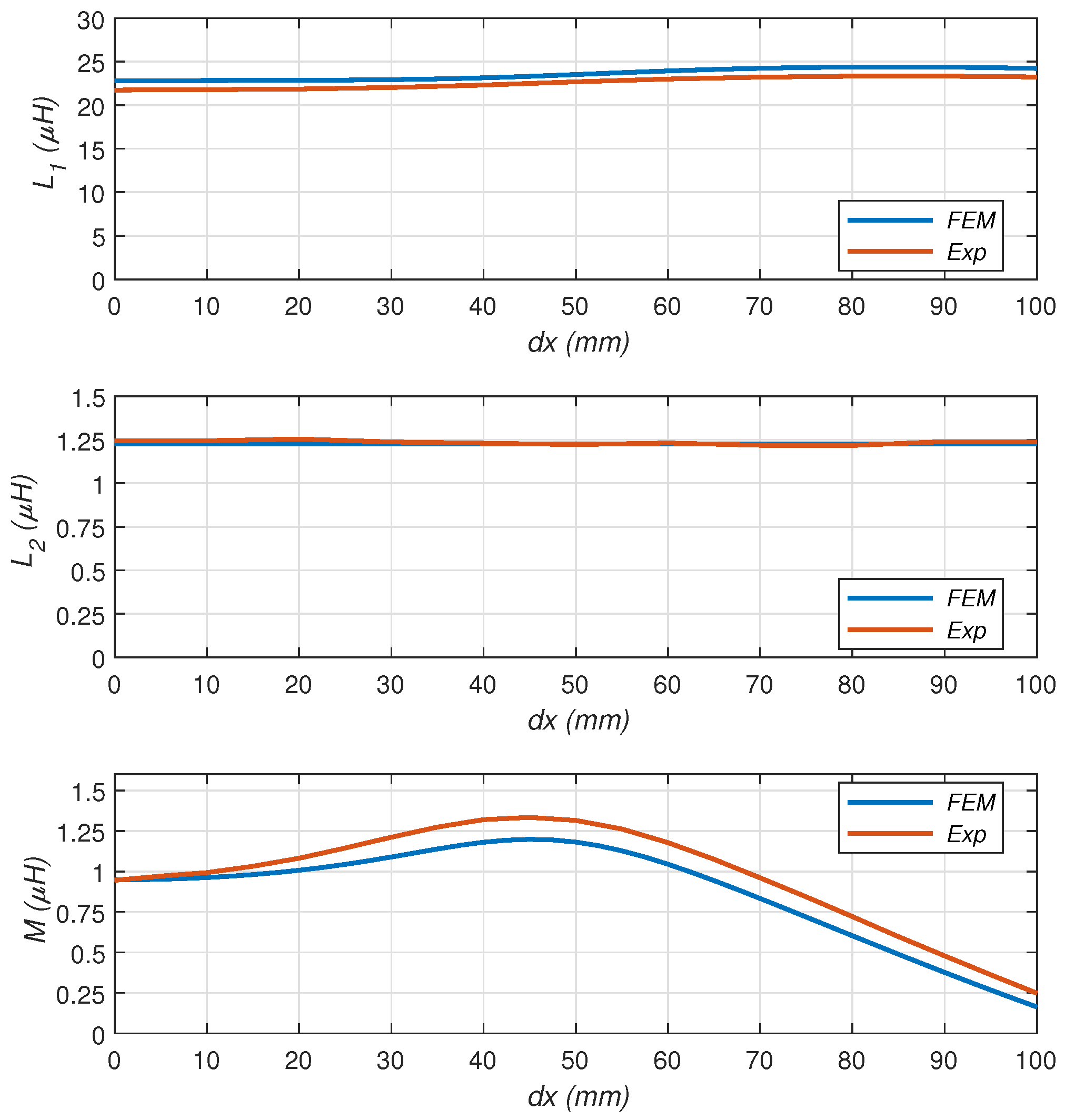
Figure 7 illustrates the variation of the system’s main inductances versus misalignment. The FEM and experimental results show almost identical trends with less than 10% error. The primary self-inductance
remains relatively constant despite misalignment with a slight increase beyond 50 mm due to the displacement of the ferrite above the receiver coil. Since the two coils are positioned closely together (10 mm apart), the ferrite above the receiving coil has an influence on the primary inductance.
The secondary self-inductance remains unchanged versus misalignment, since it is fixed to the ferrite. With the receiver coil fixed below the ferrite, the ferrite maintains a constant impact on the versus misalignment.
For the mutual inductance M, a progressive increase is observed up to 50 mm misalignment, which is followed by a decrease beyond this point. This curve indicates that maximum coupling between the two coils occurs when their axes are misaligned by approximately 50 mm. This can be explained by the size difference between the coils. The receiver coil, being half the size of the transmitter coil, is able to capture a higher magnetic field density from the transmitter when misaligned compared to when the two coils are perfectly aligned.
3.5. Coupler Efficiency Analysis
The maximum efficiency that the coupler can achieve Equation (1) was first estimated with FEM results using the FEM inductances and DC resistance of coils; however, at 150 kHz, the AC resistance of coils become significant, which is why the measured AC resistance of the coils and measured inductances were used for a real coupler efficiency estimation (
Table 3).
Figure 8 illustrates the coupler’s maximum efficiency as a function of misalignment. The curve shows an 80% efficiency from 0 mm to 70 mm of misalignment, reflecting strong coupling between the two coils. Beyond 70 mm, a drop in efficiency is observed up to 100 mm of misalignment explained by the weak coupling between coils seen in the mutual inductance curve (
Figure 7).
The efficiency curve highlights the coupler’s effective performance across varying levels of misalignment, leading to a further study of the overall energy efficiency of the WPT system under misalignment conditions.
3.6. WPT System Evaluation
In this section, an evaluation of the whole WPT system efficiency was developed. A simulation of the electrical circuit (
Figure 2) on LTspice was carried out, and the efficiency of the system was calculated using Equation (4), which represents the ratio between the active power consumed by the load and the active power supplied by the charging station.
A power «
» of 63 W was imposed at the load level
to charge the
battery (
Figure 9) in 1 h, and a voltage of 12.6 V was set as the charging voltage «
». Based on these two parameters, the load equivalent resistance «
», which corresponds to the UAV’s battery plus the AC/DC full bridge rectifier, was calculated at the first harmonic using Equation (5).
As for compensation capacitors, according to [
23,
24], capacitors
and
are obtained via Equation (6) for SP compensation topology to ensure working at resonance.
The source power
was adapted to ensure the 63 W load power with a limit of 120 W (
Table 4). This AC power source is provided by a DC source followed by a half-bridge inverter, as shown in
Figure 10. The inverter and its LTspice model were developed and provided in the laboratory.
Real components values were measured and taken into consideration for a realistic simulation approach. Resistors and represent the total resistance of the primary and secondary blocks (series resistances of coils plus capacitors). The capacitors’ equivalent series inductances (ESLs) were neglected compared to the coils’ inductances.
The overall characteristics of the WPT system are summarized in
Table 4.
Simulations versus misalignment were run.
Figure 11 shows the source and load voltages and currents in the time domain. Both primary and load currents
,
are in phase with their respective voltages
and
; this indicates an adequate compensation of inductive reactances and operation in resonance.
At 65 mm misalignment (
Figure 11b), a phase shift between the primary current and voltage begins to appear as the coils are further misaligned. This is due to weak coupling and variation in the mutual inductance
M as a result of the secondary coil being further misaligned with the primary coil, which led to losing the compensation on the primary bloc.
Further simulations were ran, and power efficiency was calculated versus misalignment via RMS values of signals for each misalignment case to evaluate the system’s response at misalignment conditions.
The efficiency curve (
Figure 12) shows the same shape as the mutual inductance with an efficiency drop from 70 mm misalignment corresponding to weak coupling between coils. The efficiency level is approximately between 60 and 76% in the 0 to 70 mm misalignment range; this is due to Joule losses in coils and in capacitors. One other reason for the efficiency drop from 70 mm misalignment is the phase shift between the source current and voltage (
Figure 11b). This phase shift is the result of an incomplete compensation of reactive energy at the primary level. The incomplete compensation is caused by the relation between the primary compensation capacitor
and the mutual inductance
M (Equation (6)), which changes as a function of the misalignment. These results lead to pursuing the study with a different compensation topology that isolates the value of the capacitors from the mutual inductance with the aim of obtaining a WPT system that is more tolerant to misalignment and more effective for the UAV.
4. Parametric Studies
Following the validation of the coupler inductances and the evaluation of the system efficiency with SP compensation, parametric studies have been carried out to analyze the influence of different parameters on the WPT performance. A parametric study allows for the systematic modification and analysis of multiple variables, aiming to enhance the system’s overall performance.
To explore alternatives to the challenges identified in the previous configuration, compensation topology and the coils’ number of turns were studied, aiming for a coupler configuration with potential improvements. Additionally, a frequency study was carried out to determine the appropriate frequency for the final coupler configuration.
For easy reading, the configurations will be described by × , where they are composed with turns for the primary coil and turns for the secondary coil.
4.1. Compensation Topology and Number of Turns
As an alternative to SP compensation topology, SS topology (
Figure 13a) was studied. In this configuration, capacitor
no longer depends on the mutual inductance (Equation (7)), which varies with misalignment.
However,
Figure 13b shows lower misalignment tolerance for the 8 × 2 configuration when SS compensation is adopted. According to [
25], to reach high efficiency levels and better misalignment tolerance for this compensation topology for the same frequency, it is preferable to choose a sufficiently high number of turns for both coils.
In order to find an effective and suitable configuration for the number of turns for this compensation topology, different configurations were studied (
Table 5).
Inductances of each configuration were obtained via FEM modeling and measured versus misalignment following the same process previously seen in
Section 3.3 and
Section 3.4. Then, their coupler efficiencies
were examined (
Figure 14).
Figure 14 shows efficiency levels of around 90% versus misalignment, up to 80 mm misalignment for all four configurations, with a slight increase of efficiency level with the number of turns. From 80 mm misalignment onwards, efficiency drops as the receiver coil is mostly outside the perimeter of the transmitter coil, causing weak coupling between coils.
Afterwards, an evaluation of power efficiency was carried out via simulations (
Figure 15) to assess the performance of each configuration in real operating conditions.
It is important to note that the series resistance of the compensation capacitors was fixed at 50 mΩ (
Table 5) to perform the correct comparison between the different configurations studied. These resistances can change depending on how the value of the capacitor was obtained (by taking one capacitor or multiple capacitors in series/in parallel for example) and on the capacitor’s type, and according to these resistances, the efficiency of the WPT system can change, since they are directly related to Joule losses in the system.
Results of the simulations (
Figure 16) show that the more turns the coils contain, the better the efficiency and the tolerance to misalignment; configurations 6 × 6 and 8 × 8 have close efficiencies of approximately 78% with misalignment tolerances up to 75 mm.
The difference in tolerance to misalignment between the maximum coupler efficiency curves (
Figure 14) that can go up to 90 mm misalignment and power efficiency curves (
Figure 16) that can undergo 75 mm misalignment is that in power efficiency evaluation, compensation capacitors are taken into account, and beyond 75 mm misalignment, capacitor
no longer provides full compensation. At this misalignment distance, the primary inductance changes due to the proximity of the two coils and the displacement of the ferrite above the secondary coil, affecting the overall system performance.
The choice between the 6 × 6 and 8 × 8 configurations favors the configuration 6 × 6. This configuration has fewer turns on the receiving part compared to the configuration 8 × 8, which is crucial for reducing the weight of the secondary block to be integrated into the UAV. Furthermore, according to
Figure 17, this configuration presents more tolerance to misalignment than the 8 × 2 configuration with SP compensation presented in
Figure 12, which is why this configuration, with SS compensation, will be tested in
Section 5 for experimental validation.
In other cases, where the misalignment tolerance is a higher priority than weight, configuration 8 × 8 might be a better choice. Therefore, the results of these studies will depend on the specific objectives sought.
4.2. Frequency Study
In order to check the frequency choice, the maximum coupler efficiency (Equation (1)) of the 6 × 6 configuration with SS compensation was analyzed at perfect alignment across different frequencies.
Figure 18 shows the coupler efficiency augmentation with frequency increase. For a 80 to 90% coupler efficiency, the frequency must be at least 115 kHz. Opting for 150 kHz ensures a satisfying choice for efficiency. Choosing higher frequency can lead to higher switching losses and higher electromagnetic interference.
Once the frequency and coupler configuration were determined, experimental testing of the system was carried out in order to validate simulation results and system performance.
5. Experimental Test Bench
The test bench used to measure the power efficiency of the WPT system and to validate the simulation model is shown in
Figure 19 and
Figure 20. The setup consists of a DC power source, an inverter, a primary compensation capacitor connected to the coupler, a secondary compensation capacitor and an equivalent resistive load. An oscilloscope is used to visualize the currents and voltages present in the system. The receiver coil is mounted on a controlled mechanic arm to enable misalignment studies.
A reduced-power model of the WPT system was implemented, multiple tests were run under misalignment conditions, and the system’s efficiency was evaluated versus misalignment. The settings of the experimental bench are described in
Table 6.
Figure 21 shows the time response of the source and load voltages and currents for two misalignment cases: 0 mm and 90 mm. In the first case of 0 mm misalignment, the obtained curves show correlation with the simulation results (
Figure 11) with a difference in power level. This correspondence indicates that the model accurately simulates the essential characteristics of the real system, such as resonances and losses.
At 90 mm misalignment, a phase shift between the primary current and voltage is observed. This is due to weak coupling and variation in the transmitter self inductance caused by the proximity of the ferrite on top of the secondary coil, which led to losing the compensation on the primary bloc.
Results Analysis
The RMS values of the currents and voltages were measured for each case of misalignment to calculate the power efficiency of the system (Equation (4)) versus misalignment.
The efficiency curves from both experimental and simulation results (
Figure 22) exhibit similar trends with an error margin of less than 10%. The efficiency level remains between 70 and 80%. This is largely due to the chosen operating frequency (
Figure 18), where the maximum achievable efficiency of the coupler was observed to be approximately 85–90% at 150 kHz. Additionally, Joule losses in the components further reduce the overall system efficiency to 70–80% with a misalignment tolerance limit of 75 mm. Beyond this point, the system operates at an efficiency below 70%.
It is possible to improve the system’s efficiency level by increasing frequency; however, higher frequencies can lead to higher switching losses and higher electromagnetic interference to explore.


