Abstract
The efficacy of visual Simultaneous Localization and Mapping (SLAM) diminishes in large-scale environments due to challenges in identifying distant landmarks, leading to a limited perception range and trajectory drift. This paper presents a practical method to enhance the accuracy of feature-based real-time visual SLAM for compact unmanned vehicles by constructing distant map points. By tracking consecutive image features across multiple frames, remote map points are generated with sufficient parallax angles, extending the mapping scope to the theoretical maximum range. Observations of these landmarks from preceding keyframes are supplemented accordingly, improving back-end optimization and, consequently, localization accuracy. The effectiveness of this approach is ensured by the introduction of the virtual map point, a proposed data structure that links relational features to an imaginary map point, thereby maintaining the constrained size of local optimization during triangulation. Based on the ORB-SLAM3 code, a SLAM system incorporating the proposed method is implemented and tested. Experimental results on drone and vehicle datasets demonstrate that the proposed method outperforms ORB-SLAM3 in both accuracy and perception range with negligible additional processing time, thus preserving real-time performance. Field tests using a UGV further validate the efficacy of the proposed method.
1. Introduction
Simultaneous Localization and Mapping (SLAM) is a technique that concurrently estimates the poses of a platform and maps the details of an environment through sensory perception. It has emerged as a promising approach for the localization of autonomous unmanned vehicles, particularly in GNSS-denied environments. With significant advancements over the recent two decades, SLAM has been successfully demonstrated in indoor, building-scale environments; however, it remains challenging for SLAM operated over extended periods and larger areas [1], such as in autonomous driving [2], ocean exploration [3] or precision agriculture [4]. The limited detection range of sensors restricts the scope of perception, posing a risk to mapping with insufficient coverage and to localization with a trajectory drift.
Cameras as sensory instruments offer incomparable advantages in being lightweight and cost-effective, making vision-based SLAM an attractive option for unmanned vehicle applications [5,6]. In addition, images contain a wider scope of information, including pixels projected from distant landmarks, which has the potential to extend the perception range of SLAM systems in large-scale environments. However, direct measurements of distances using a camera require an auxiliary camera (e.g., stereo camera or depth camera) or additional sensor (e.g., LiDAR or other ranging sensors), which still suffers from accuracy degradation as the range increases. To map distant landmarks utilizing projected pixels, structure computation is performed across different viewpoints, which is a fundamental process in feature-based visual SLAM.
In modern feature-based SLAM, pixels corresponding to the same spatial point, referred to as image features, are typically associated and constructed into a map point within a small batch of consecutive images. The batch size is constrained to maintain the algorithm efficiency, which limits the maximum search range for features in conventional feature-based SLAM, leading to insufficient parallax for triangulating distant landmarks.
This paper presents an effective method for constructing distant landmarks, which extends the mapping range and improves the localization accuracy of feature-based SLAM in large-scale environments while maintaining real-time performance. The main contributions of this work are as follows:
- The limitation of the conventional SLAM algorithm in large-scale environments is revealed by discussing the perception range constrained by the triangulation parallax angle. By enhancing the covisibility of keyframes for the graph optimization, a methodology is proposed to improve SLAM by the observation of distant landmarks.
- The concept of the virtual map point is introduced, representing a map point candidate without a determined spatial coordinate. By continuously tracking corresponding features across frames through this data structure, distant map points can be triangulated once sufficient parallax angles are achieved, expanding the mapping range of visual SLAM. Meanwhile, these features are related, monitored, and retrieved effectively and preciously without extending the range of local mapping, thus constraining the scale of optimization.
- An example SLAM software incorporating the proposed method is implemented based on the open-source ORB-SLAM3 code. Experiments conducted on drone and vehicle datasets, along with field tests on an embedded system in a UGV, demonstrate that the proposed method surpasses the state-of-the-art baseline system in terms of perception range, enhancing localization accuracy while maintaining real-time performance.
This paper is organized as follows. Related works on the evolution of visual-based SLAM in large-scale environments are briefly surveyed in Section 2. The cause of limited perception ranges in feature-based SLAM is analyzed in Section 3, with a discussion of the possibility of enhancing the accuracy of localization by distant landmarks. The methodology and implementation details are introduced in Section 4. In Section 5, the experiments conducted with the proposed method on datasets and in the real world are presented, with discussions on experimental results. The contribution of this paper is concluded in Section 6.
2. Related Works
For direct methods of visual SLAM, frame poses are estimated by minimizing the photometric error of pixels, which is less affected by the distance of landmarks. Some direct methods can be applied in large-scale indoor scenes, such as LSD-SLAM, and in outdoor scenes, such as the succeeding DSO [7]. Since minimizing intensity error typically requires a denser sampling of pixels, a key challenge for large-scale direct SLAM lies in the computational burden of back-end optimization for global consistency, affecting both runtime and memory usage. In SVO and the succeeding SVO Pro [8], minimization is sparsified/ becomes sparse by selecting corners and features among pixels, thereby enhancing robustness and efficiency in outdoor environments. DSM [9] advances the technique of photometric bundle adjustment (PBA) toward building a persistent global map. However, the fundamental of direct methods relies on the intensity-invariant assumption, which is significantly challenged in long-term, large-scale scenarios.
Conversely, in the majority of feature-based SLAM algorithms, the accuracy of pose estimation is heavily dependent on the quality of the constructed landmarks, raising concerns about the mapping range in large-scale environments.
In the filtering era of visual SLAM, limiting the size and quality of landmarks was crucial for large-scale SLAM. Now that the bundle adjustment of keyframes has been proven to outperform filtering in efficiency, increasing the number of features has been shown to improve accuracy [10]. Ever since the feasibility of decoupling mapping from localization was demonstrated in PTAM [11], numerous methods have been developed to enhance visual SLAM by improving the construction and management of landmarks from features without the strict constraint of immediacy.
The depth of the landmarks in conventional approaches is estimated based on the motion of the camera, similar to structure from motion (SFM). In most feature-based methods, the perception of landmarks relies on the precise triangulation of features, which directly affects the accuracy of feature tracking in subsequent localization. To construct landmarks with larger depth, DT-SLAM [12] defers triangulation until a sufficient baseline is achieved in a subsequent keyframe. In ORB-SLAM [13], the range of triangulation candidates is further extended to a set of preceding keyframes with covisiblity.
To further extend the range of visual mapping, auxiliary sensors can be introduced to cooperate with cameras, providing an instant depth measurement of landmarks within a frame. RGB-D cameras can directly provide pixel depths using structured light or time-of-flight (ToF) within a short range, which can be used in large-scale indoor environments [14]. In large-scale outdoor environments, point clouds generated by ranging sensors can assist the camera with depth information, such as LIMO [15] and LOFF [16] with LiDAR.
As for secondary cameras, stereo vision can provide depth image similar to point clouds of RGB-D camera. Nevertheless, stereo cameras in visual SLAM are typically used for triangulating features on landmarks instantly within the frame [17]. In addition to the depth measurement of pixels, some multi-camera systems can provide a wider field of view and expand the perception width. However, the range of triangulation depth is directly constrained by the baseline length of the cameras. In large-scale SLAM applications, such as autonomous driving, the baseline of a stereo or multi-camera system can reach several decimeters, which is too bulky for most unmanned platforms. Moreover, the measurement of depth assisted by auxiliary sensors or secondary cameras is inherently bounded by instrumental limitation and can typically only supplement the mapping in most situations.
Consequently, many visual SLAM research works focus on computer-vision-based approaches in large-scale environments, and most approaches focus on better recognizing and managing the landmarks. For instance, Xue et al. [18] semantically labeled entire buildings as instances in the database for recognition. MS-SLAM [19] sparsified the map by removing redundant nonlocal map points to achieve memory efficiency, facilitating the scalability in large-scale environments. However, the perception range while mapping and its relationship with localization accuracy are rarely discussed. This issue brings the topic back to the construction of landmarks from motion. The perception, or at least the sensation, of remote landmarks remains a concern in large-scale visual SLAM.
3. Perception of Distant Landmarks in SLAM
3.1. Triangulation Error and Parallax Angle
As illustrated in Figure 1, a spatial point with world coordinates is observed from two camera viewpoints with camera centers and . The projection of onto images and are and , respectively. According to the epipolar constraint in multiple-view geometry, the points , , and , are coplanar. Given the camera extrinsics for each camera pose, the position of can be determined by the intersection of the back-projected rays and , satisfying
where , and are homogeneous coordinates. Applying the direct linear transformation (DLT) [20], a linear equation can be formulated as
where and . can be computed numerically by singular value decomposition (SVD), considering the measurement error of the camera.
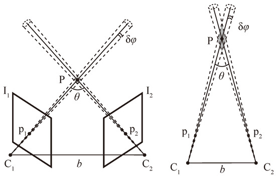
Figure 1.
Triangulation of a spatial point. The uncertainty of triangulation is represented by the gray area. The case illustrated on the right has a shorter baseline b and/or a smaller parallax angle , resulting in greater uncertainty in the localization of .
To be more specific, when the projection point moves by , the angular displacement of the sight angle causes a corresponding change in the estimation of . A larger baseline or parallax angle results in significantly smaller , thereby reducing the uncertainty in the estimation of [21], and vice versa. The measurement error of and the estimation error of and bring similar and thus uncertainty to the estimation of . Given that baseline length correlates positively with the distance to the spatial point, a threshold is set to ensure a minimum parallax angle during triangulation in SLAM.
3.2. Perception Range of Feature-Based SLAM
In typical feature-based SLAM, image features corresponding to new landmarks are searched and matched within the new frame and a batch of adjacent keyframes. After triangulation, the coordinates of local landmarks, together with the poses of local keyframes, are filtered or optimized to minimize the reprojection error in each keyframe, thereby reducing triangulation errors. This procedure is known as local mapping, and the candidate keyframes are typically designated by a sliding window or covisibility graph. To maintain real-time performance, the batch size for local mapping is bounded, which limits the maximum length of baseline. Since the minimum parallax angle is fixed as aforementioned, the maximum distance of the perception range is constrained in conventional SLAM systems, as illustrated in Figure 2.
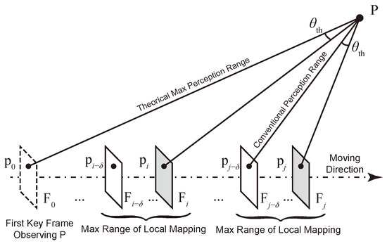
Figure 2.
Extending the perception range to the maximum by utilizing features from keyframes beyond the local mapping range.
To extend the perception range and accurately triangulate distant landmarks, the baseline can be extended by searching for corresponding features in preceding keyframes outside the local mapping batch, starting from the initial observation of the landmark by the camera. Once a sufficient parallax angle is established between the new frame and a past keyframe, the distant landmark can be triangulated with acceptable uncertainty. Since corresponding features have been matched in preceding keyframes, the observation of constructed landmarks is subsequently integrated into these frames. This approach enables earlier triangulation of distant landmarks than conventional methods, thereby maximizing the perception range of SLAM.
3.3. Localization Enhanced by Distant Landmarks
In contrast to indoor environments, landmarks in large-scale environments are distributed across a wider range of distances. While nearby landmarks may suffice for short-term localization, the perception of distant landmarks, expected to be observed through longer range, is crucial for long-term applications as it enhances the covisibility of keyframes.
The error of observation during SLAM is represented as
where concatenates the states of camera poses and landmarks , represents the error around the current estimated state , and is the Jacobian matrix of the error function .
In typical feature-based SLAM systems with an optimization-based back-end, the incremental linear equation of optimization for camera poses and landmarks is established as
where is the optimal perturbation, is the Hessian matrix, is the information matrix, and is a constant vector in each iteration [22]. The subscripts C and P represent camera poses and landmarks, respectively.
In the bundle adjustment with graph optimization, takes an arrowhead structure with a sparse pattern. The blocks and are diagonal due to the independence of distribution within camera poses and map points. The dimension M of is significantly smaller than the dimension N of in the context of SLAM. A block in is non-zero only when the camera pose has an observation of .
In large-scale SLAM, it is common for camera viewpoints along a long trajectory to have limited overlap in the observation of landmarks due to a restricted perception range. For camera poses and , which do not observe the same landmarks, their relationship and constraints are relayed by intermediate poses and landmarks , as illustrated in Figure 3a. The Hessian block matrix for this local part is diagrammed in Figure 3b. In the absence of direct constraint between and within , the risk of drift increases during pose and landmark estimation using Equation (6).
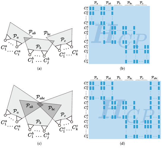
Figure 3.
The relationship between the perception ranges of the camera and the structure of the matrix . The case in (a) has shorter perception range, with represented as (b). While the case in (c) has longer perception range, with augmented by the commonly observed landmarks , represented as (d). Note that many of the block matrices in dark blue remain zero due to the absence of observation between corresponding camera pose and landmark .
With the extension of perception range, the observation of distant landmarks can be supplemented across aforementioned camera poses, as illustrated in Figure 3c. The number of covisible landmarks and are enriched, and landmarks that can be commonly observed by all sets of pose are supplemented. is augmented accordingly, as diagrammed in Figure 3d, thereby enhancing constraints during optimization and reducing the likelihood of drift. Furthermore, distant landmarks can be recognized over a broader scope and are less likely to be occluded by other objects, which can aid in loop closure, improve global positioning, and enhance relocalization from kidnapping scenarios.
On the other hand, optimization efficiency can be preserved by maintaining the batch size of camera poses. Equation (6) can be marginalized with Schur elimination, yielding the following expression:
The complexity for each iteration to determine is [23], primarily dictated by the number of poses M, given that . By limiting the amount of poses to optimize, the bundle adjustment with additional constraint remains computationally feasible, especially when conducted in a thread parallel to real-time tracking.
Thus, to enhance real-time large-scale visual SLAM, the proposed method should perform the following:
- Construct distant landmarks as early as possible;
- Constrain the batch size of keyframes to optimize while constructing landmarks.
4. SLAM System with the Virtual Map Point
With maintaining a bounded size of local mapping, distant map points can be triangulated using matched features between a new frame and the preceding frame with a sufficient parallax angle. However, it is time-consuming to traverse preceding keyframes, retrieve features and match them correctly.
Considering that unmapped features in preceding frames have already/previously been extracted, matched and had triangulation attempted to be performed on, managing these data for later triangulation is both convenient and beneficial. By threading and indexing features corresponding to potential distant map points for a real-time SLAM system, a data structure named the virtual map point (VMP) is introduced in the proposed method.
4.1. Virtual Map Point
A virtual map point is defined as a provisional map point, representing a landmark that is observed by the camera but whose spatial coordinate cannot be determined at the moment. A virtual map point can be considered a pre-built candidate for a distant map point.
Through the virtual map point, observations of a remote landmark from frames are registered to this data structure. Unlike a normal map point whose spatial coordinates are determined immediately after observation, the virtual map point and corresponding observations are to be managed by the SLAM system over a period of time. The following are key motivations behind the design of the data structure of the virtual map point:
- Efficient Parallax Inspection: Through computing angles between back-projected rays from observed frames, the maximum parallax angle among frames is continuously updated within the data structure. This procedure is detached from the optimization for tracking or mapping; thus, the angle can be inspected constantly but effectively, which consumes minimal computational resources, ensuring timely awareness of enough parallax.
- Rapid Frame Retrieval: The features corresponding to the same distant landmark are continuously attached to the data structure. Instead of searching for frames outside the range of local mapping by feature matching, the frame corresponding to sufficient parallax angle can be retrieved effectively through indexed features.
- Seamless Conversion to Map Point: Once the spatial coordinates of a virtual map point are determined, the observation from historical frames is inherited when constructing the corresponding map point. This relationship of observations enhances covisibility between frames and is crucial for further local and global optimization in the SLAM system.
Based on these principles, the pipeline for constructing and managing a virtual map point is outlined as follows. When a landmark is observed by two frames with a small parallax angle, a virtual map point is instantiated, storing references to the corresponding features and frames. Observations of the virtual map point are concurrently added to the frames. As the camera continues moving, features in subsequent frames are matched and associated to the virtual map point. The parallax angle between the new frame and the stored frames is computed within the virtual map point. Once sufficient parallax is accumulated, the spatial coordinates are triangulated. Subsequently, a new map point is constructed from the triangulated virtual map point, inheriting preceding observations from the frames. A diagram of a virtual map point is illustrated in Figure 4.
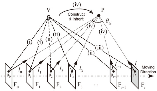
Figure 4.
A diagram of a virtual map point. (i) The virtual map point is constructed from features matched from two adjacent frames. (ii) As the camera moves, features and back-projected rays in subsequent frames are associated with , allowing for the calculation of the maximum parallax angle. (iii) The spatial coordinates of are triangulated when the parallax angle exceeds the threshold . (iv) Subsequently, a map point is constructed from , inheriting the observation relationships with frames ranging from to .
Compared to a normal map point, a virtual map point contains nearly identical information, including indices to corresponding features and observed frames, except for the spatial coordinates. Consequently, the construction, maintenance and conversion of virtual map points can be processed alongside normal map points during mapping, conserving computing resources and time.
4.2. Software Implementation Based on ORB-SLAM3
To validate the efficacy and efficiency of the proposed method, a real-time SLAM software is implemented based on an existing SLAM system, which also serves as a baseline for comparison in the experiments. ORB-SLAM3 [24], one of the most popular feature-based open-source SLAM systems with state-of-the-art performance, is selected as the base system. An overview of the proposed system is illustrated in Figure 5.
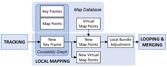
Figure 5.
An overview of the proposed SLAM system. The management of virtual map points is integrated into the “Local Mapping” thread of ORB-SLAM3.
Parallel to map points, virtual map points are created and managed by the “Local Mapping” thread, where the major modifications of the proposed method take place. When the new keyframe is passed from the “Tracking” thread, a covisibility graph is organized with local keyframes and map points in the “Local Mapping” thread. Features are then matched between the new keyframe and each of the local keyframes. Features with sufficient parallax are triangulated into new map points, whereas low-parallax features are constructed into virtual map points or associate to existing virtual map points for update. Once the maximum parallax angle exceeds the threshold after the update, the virtual map point is triangulated and converted to new map point, retaining preceding observation relationships. The details of mapping with a virtual map point are stated in Algorithm 1.
| Algorithm 1 Mapping with virtual map points. |
Input: New frame with n features and pose ; Adjacent keyframe with features and pose ; Output: New map points and virtual map points ;
|
Once all the new map points and new virtual map points are created, a local bundle adjustment is executed within the covisibility graph together with the new map points, optimizing
where are triangulated virtual map points together with other new map points and local map points, are local keyframes, and are other covisible keyframes of local keyframes. is the reprojection error of in , and is the robust Huber cost function [25]. Through a local bundle adjustment, the coordinates of converted virtual map points are further optimized, eliminating inconsistent triangulation. Afterwards, the new keyframe is conveyed to the “Loop and Map Merging” thread, searching for a possible loop closure.
The threshold of the parallax angle is set to in ORB-SLAM3, which remains unchanged in our method for a better comparison. Some low-parallax features are discarded in ORB-SLAM3 due to a threshold of the triangulation baseline for corresponding local keyframes, defined as
where is the baseline of the stereo camera and is the median depth of map points observed by the new frame. Keeping unchanged, these features are also retained in our method to be constructed or associated to virtual map points.
5. Experimental Results and Discussion
5.1. Dataset Tests
To verify the proposed method, dataset experiments are conducted using both ORB-SLAM3 and the proposed system for comparison. Some image sequences in large-scale environments with accurate groundtruth are selected from popular datasets for visual SLAM.
Collected by a vehicle in city scenes, the KITTI Dataset [26] is widely tested by many visual SLAM algorithms. Consequently, all 11 sequences are tested and compared in this paper. Collected indoors by a drone, the EuRoC Dataset [27] is also widely used due to the accuracy of groundtruth tracked by a laser tracker. Rather than the Vicon Room sequences, the Machine Hall sequences are chosen for their larger depth of field.
In addition to classical datasets, some popular datasets with long-range sequences and large-scale scenes are tested in this paper. Collected by a vehicle in metropolitan scenes, the KAIST urban dataset [28] is tested with a subset of complex routes. The Zurich Urban Micro Aerial Vehicle Dataset [29] is also tested in this paper due to the long duration of recording by a quadrotor drone.
The experiments have been conducted on an Intel Core i7-12700K@3.6GHz computer, without the utilization of GPU acceleration. The image sequences are processed in monocular mode, producing poses of keyframes as trajectory and map points as the map. A transformation with the Umeyama algorithm is applied to align the trajectory with groundtruth due to the ambiguous scale. In both methods, the number of extracted features per frame is set to 1000 for the EuRoC dataset and 2000 for the rest, according to the resolution.
The root mean square of absolute trajectory error (RMS ATE) is calculated to evaluate the accuracy of localization. For each sequence, multiple experiments are conducted with both methods, and the metric results featuring median RMS ATE are listed in Table 1 and Table 2. Mean tracking time per frame is calculated to verify the real-time performance of the algorithms. The depth of triangulation during the construction of map points is recorded, along with the distance of map points observed by keyframes. The median depths and distances are provided in the table for reference. The amount of map points is listed, indicating the size of the map. Additionally, the percentage of map points converted from virtual map points is provided for the proposed method.

Table 1.
Classical SLAM dataset results and comparison.

Table 2.
Long-range dataset results and comparison.
5.2. Discussion on Dataset Tests
5.2.1. Accuracy of Localization
The proposed method exceeds the baseline ORB-SLAM3 system in all sequences, with a consistently lower RMS ATE of keyframe trajectories.
In the KITTI sequences, the range of reduced RMS ATE is from in sequence 03 to in sequence 08. In sequence 04, the proposed method reduces the RMS ATE by a maximum proportion of 44.42% compared to ORB-SLAM3. Although both methods underperform in sequence 01, the proposed method achieves 11.85% less RMS ATE than ORB-SLAM3.
In the KAIST sequences, which are more lengthy and complicated than the KITTI sequences, the proposed method outperforms ORB-SLAM3 by a significant margin. The minimum reduced RMS ATE is in sequence 27 by 14.43%, and the maximum is in sequence 39 by an impressive 60.15%.
For aerial datasets, the RMS ATE is reduced by during a flight in the UZH MAV sequence. In the indoor environment of the EuRoC sequences, the improvement in accuracy is diminished due to the short range of motion and limited scale of the environment, though the maximum reduction in RMS ATE occurs in the sequence of Machine Hall 05 with a proportion of 17.67%. The EuRoC dataset test indicates that while the proposed method is designed for large-scale environments, it does not degrade in indoor environments.
The keyframe trajectories of selected sequences, highlighted in bold in the tables, are compared in Figure 6 from the top view, which are plotted by EVO [30].
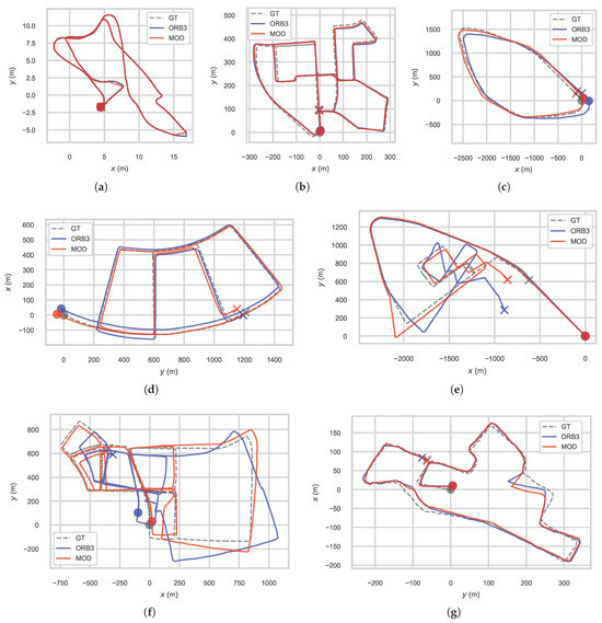
Figure 6.
Keyframe trajectory comparison between ORB-SLAM3 (ORB3) and the proposed method (MOD) alongside groundtruth (GT) from the top view in sequences of (a) EuRoC Machine Hall 05, (b) KITTI 00, (c) KAIST 32, (d) KAIST 27, (e) KAIST 33, (f) KAIST 39 and (g) UZH MAV during the dataset test.
5.2.2. Range of Mapping
Compared with the baseline ORB-SLAM3 system, the proposed method creates map points with greater triangulation depths, thereby extending the perception range during mapping.
The median map point triangulation depth in the proposed method is universally larger than that in ORB-SLAM3. The only exception occurs in indoor sequence EuRoC MH 03, where the median depths in the two methods are sufficiently close, with a disparity of 0.42%.
Corresponding to trajectories in Figure 6, the distribution of the triangulation depth of map points is illustrated in Figure 7a. Compared with ORB-SLAM3, the map points of the proposed method converge at greater depths. To further analyze the distribution of the triangulation depth in the proposed method, the comparison between normal map points and map points converted from virtual map points is illustrated in Figure 7b. The distribution of the triangulation depth of normal map points in the proposed method is similar to that in ORB-SLAM3. However, the converted virtual map points converges at significantly greater depth than normal map points, demonstrating that the expansion of the perception range is attributed to the utilization of virtual map points.
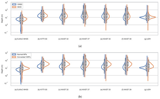
Figure 7.
The distribution of triangulation depth of map points in dataset tests: (a) Comparison between ORB-SLAM3 (ORB3) and the proposed method (MOD); (b) comparison between normal map points and map points converted from virtual map points within the proposed method.
Consequently, landmarks of larger distance are observed during frame tracking, manifested by the universal promotion in the median observation distance of map points. A comparison of the perception and observation range for the two methods is given as an example in Figure 8. In the proposed method, the remote white buildings are initially observed in the 2776th frame of the sequence KAIST 26, with the corresponding converted virtual map point beginning to be continuously tracked. After a time interval of with of displacement, the same buildings are initially observed in the 2979th frame by ORB-SLAM3. Meanwhile, several converted virtual map points on the buildings have been constructed and tracked for a period in the proposed method, continuously guiding the localization of the platform. Covisibility relationship is then expanded by the converted virtual map points, enhancing local and global optimization for keyframes and map points.
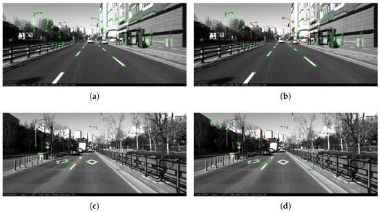
Figure 8.
The observation on map points in the 2776th frame of the sequence KAIST 26 by (a) ORB-SLAM3 and (b) the proposed method, and in the 2979th frame by (c) ORB-SLAM3 and (d) the proposed method, with normal map points denoted in green and converted virtual map points denoted in red.
In summary, the extended range of perception by distant landmarks contributes to the improvement in the accuracy of localization in visual SLAM, especially under large-scale and long-range situations.
5.2.3. Real-Time Performance
The proposed method maintains real-time performance comparable to the baseline ORB-SLAM3, with negligible extra processing time.
The mean tracking time listed in the tables suggests that both the methods may process the frames quicker or slower independently of other factors. Additionally, the mean tracking time fluctuates across all the sequences in the same dataset. Since the experiment has been conducted repeatedly for each sequence in both methods, the mean tracking time of every experiment is collected. The statistics are illustrated in Figure 9, containing tens to over a hundred trials for each dataset.
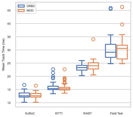
Figure 9.
Comparison of statistics on mean tracking time across the dataset and field tests between ORB-SLAM3 (ORB) and the proposed method (MOD).
The median of mean tracking time in ORB-SLAM3 is , and for EuRoC, KITTI and KAIST, respectively. In the proposed method, the median of the mean tracking time is , and , respectively. It is expected that the proposed method would consume more time than the base system due to the additional management of virtual map points. However, the distribution of mean tracking time is similar in both methods, and the difference of the median is negligible, being under .
The difference in the amount of map points may provide some clues. The map points in the proposed method are slightly fewer than those in ORB-SLAM3 for most of the sequences, which contributes to restraining the map size for long-term SLAM [31]. It is inferred that the utilization of virtual map points might reduce some repetitive or redundant map points corresponding to the same landmarks, thereby limiting the scale of the map size, and maintaining the efficiency of local mapping and global optimization. In any case, it is concluded that the proposed method can maintain the real-time performance comparable to the baseline method.
5.3. Field Tests and Discussion
To further evaluate the real-time performance of the proposed method in practical applications, field tests are conducted using an embedded system. Monocular image sequences are recorded at by an Intel D435i camera integrated into an Agilex wheeled robot with Ackermann steering. The ComNav M100 system (RTK + GNSS + INS) offers groundtruth with exceptional three-dimensional positioning precision within . The unmanned ground vehicle carrying the experimental platform is illustrated in Figure 10a. The unmanned ground vehicle is manually guided through campus scenes, including a yard, road and park. The paths on the satellite map are illustrated in Figure 10c–e.
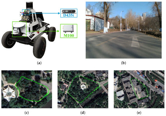
Figure 10.
(a) The experimental platform on a wheeled robot. Intel D435i collects the monocular image sequence and ComNav M100 offers groundtruth. (b) A sample of collected image sequences, which contains parts of distant landmarks. The sequences are collected in campus scenes of (c) yard, (d) road and (e) park. Location: Science Park, Harbin Institute of Technology.
The Nvidia AGX Xavier Developer Kit is selected to conduct the experiments under maximum power mode. The video stream is processed by ORB-SLAM3 and the proposed system, respectively, and repeatedly, producing keyframe trajectories. The metrics are similar to those in the dataset tests, and the median tracking time per frame is provided as a reference for real-time performance. In both methods, the number of extracted features per frame is set to 1000. The data featuring the median RMS ATE are listed in Table 3. Keyframe trajectories are illustrated in Figure 11 from the top view and the distribution of the triangulation depth of map points is illustrated in Figure 12. The statistics of mean time in repeated experiments are illustrated in Figure 9.

Table 3.
Field test results and comparison.

Figure 11.
Keyframe trajectory comparison between ORB-SLAM3 (ORB3) and the proposed method (MOD) alongside groundtruth (GT) from the top view in scenes of a (a) yard, (b) road and (c) park during the field test.

Figure 12.
The distribution of triangulation depth of map points in field tests: (a) Comparison between ORB-SLAM3 (ORB3) and the proposed method (MOD); (b) comparison between normal map points and map points converted from virtual map points within the proposed method.
In the proposed method, the reduction in RMS ATE is in the yard scene, and narrowed to and in the road and park scenes, respectively, owing to loop closure. The median depth of triangulation is enlarged, ranging from to . The results strengthen the conclusion that the proposed method outperforms the baseline ORB-SLAM3 in terms of the range of perception and accuracy of localization.
Due to the limitation of computing capability, the median of mean tracking time soars to in ORB-SLAM3 and in the proposed method. Since the frame rate of the camera is , it is confirmed that the SLAM system with the proposed method achieves real-time performance in the field test.
6. Conclusions
This paper demonstrates that the perception of distant landmarks can significantly improve localization accuracy in large-scale SLAM by expanding the mapping scope. A novel method is introduced to triangulate map points on distant landmarks, which are routinely deferred or discarded in conventional SLAM systems due to low parallax. A data structure named the virtual map point is proposed to relate corresponding features across frames and construct distant map points effectively. The proposed method is implemented based on ORB-SLAM3 codes and is validated through both dataset experiments and field tests. The experimental results demonstrate that the modified system incorporating the proposed method outperforms the base system in mapping range and localization accuracy with negligible additional time, thereby enhancing visual SLAM in large-scale environments while maintaining real-time performance.
The proposed method holds potential for improving the navigation of autonomous robots and unmanned vehicles operating outdoors over extended periods. The virtual map point structure is highly adaptable and can be integrated into other landmark-based or landmark-related visual SLAM systems, particularly applicable for perception, mapping or SFM tasks using monocular cameras or short-baseline stereo cameras.
Further improvement of the proposed method could involve refining the estimation model for the initial depth of converted virtual map points, potentially utilizing projections on images with sub-pixel accuracy during local optimization. Additionally, the extended range of visual perception could be integrated with other sensors to enhance multi-source fusion SLAM, offering a potential direction for future research.
Author Contributions
Conceptualization, H.D. and C.W.; methodology, H.D.; software, H.D.; validation, H.D.; investigation, H.D., X.Z. and B.L.; writing—original draft preparation, H.D.; writing—review and editing, H.D., X.Z., B.L., Y.J., G.W. and C.W.; visualization, H.D.; supervision, C.W.; project administration, C.W.; funding acquisition, C.W. All authors have read and agreed to the published version of the manuscript.
Funding
This research was funded by the Touyan Innovation Program of Heilongjiang Province, China.
Institutional Review Board Statement
Not applicable.
Data Availability Statement
Data is contained within the article.
Conflicts of Interest
The authors declare no conflicts of interest.
Abbreviations
The following abbreviations are used in this manuscript:
| ATE | Absolute Trajectory Error |
| DLT | Direct Linear Transform |
| GNSS | Global Navigation Satellite System |
| IMU | Inertial Measurement Unit |
| INS | Inertial Navigation System |
| LiDAR | Light Detection and Ranging |
| MAV | Micro Aerial Vehicle |
| MP | Map Point |
| PBA | Photometric Bundle Adjustment |
| RMS | Root Mean Square |
| RTK | Real-time Kinematic Positioning |
| SLAM | Simultaneous Localization and Mapping |
| SVD | Singular Value Decomposition |
| ToF | Time-of-Flight |
| UGV | Unmanned Ground Vehicle |
| VMP | Virtual Map Point |
References
- Cadena, C.; Carlone, L.; Carrillo, H.; Latif, Y.; Scaramuzza, D.; Neira, J.; Reid, I.; Leonard, J.J. Past, Present, and Future of Simultaneous Localization and Mapping: Toward the Robust-Perception Age. IEEE Trans. Robot. 2016, 32, 1309–1332. [Google Scholar] [CrossRef]
- Wang, K.; Zhao, G.; Lu, J. A Deep Analysis of Visual SLAM Methods for Highly Automated and Autonomous Vehicles in Complex Urban Environment. IEEE Trans. Intell. Transp. Syst. 2024, 25, 10524–10541. [Google Scholar] [CrossRef]
- Zhang, S.; Zhao, S.; An, D.; Liu, J.; Wang, H.; Feng, Y.; Li, D.; Zhao, R. Visual SLAM for underwater vehicles: A survey. Comput. Sci. Rev. 2022, 46, 100510. [Google Scholar] [CrossRef]
- Ding, H.; Zhang, B.; Zhou, J.; Yan, Y.; Tian, G.; Gu, B. Recent developments and applications of simultaneous localization and mapping in agriculture. J. Field Robot. 2022, 39, 956–983. [Google Scholar] [CrossRef]
- Gupta, A.; Fernando, X. Simultaneous Localization and Mapping (SLAM) and Data Fusion in Unmanned Aerial Vehicles: Recent Advances and Challenges. Drones 2022, 6, 85. [Google Scholar] [CrossRef]
- Wang, K.; Kooistra, L.; Pan, R.; Wang, W.; Valente, J. UAV-based simultaneous localization and mapping in outdoor environments: A systematic scoping review. J. Field Robot. 2024, 41, 1617–1642. [Google Scholar] [CrossRef]
- He, M.; Zhu, C.; Huang, Q.; Ren, B.; Liu, J. A review of monocular visual odometry. Vis. Comput. 2020, 36, 1053–1065. [Google Scholar] [CrossRef]
- Forster, C.; Zhang, Z.; Gassner, M.; Werlberger, M.; Scaramuzza, D. SVO: Semidirect Visual Odometry for Monocular and Multicamera Systems. IEEE Trans. Robot. 2017, 33, 249–265. [Google Scholar] [CrossRef]
- Zubizarreta, J.; Aguinaga, I.; Montiel, J.M.M. Direct Sparse Mapping. IEEE Trans. Robot. 2020, 36, 1363–1370. [Google Scholar] [CrossRef]
- Strasdat, H.; Montiel, J.; Davison, A.J. Visual SLAM: Why filter? Image Vis. Comput. 2012, 30, 65–77. [Google Scholar] [CrossRef]
- Klein, G.; Murray, D. Parallel Tracking and Mapping for Small AR Workspaces. In Proceedings of the 2007 6th IEEE and ACM International Symposium on Mixed and Augmented Reality, Nara, Japan, 13–16 November 2007; pp. 225–234. [Google Scholar] [CrossRef]
- Herrera, D.C.; Kim, K.; Kannala, J.; Pulli, K.; Heikkilä, J. DT-SLAM: Deferred Triangulation for Robust SLAM. In Proceedings of the 2014 2nd International Conference on 3D Vision, Tokyo, Japan, 8–11 December 2014; Volume 1, pp. 609–616. [Google Scholar] [CrossRef]
- Mur-Artal, R.; Montiel, J.M.M.; Tardós, J.D. ORB-SLAM: A Versatile and Accurate Monocular SLAM System. IEEE Trans. Robot. 2015, 31, 1147–1163. [Google Scholar] [CrossRef]
- Muravyev, K.; Yakovlev, K. Evaluation of RGB-D SLAM in Large Indoor Environments. In Proceedings of the Lecture Notes in Computer Science (Including Subseries Lecture Notes in Artificial Intelligence and Lecture Notes in Bioinformatics), Fuzhou, China, 16–18 December 2022; Volume 13719 LNCS, pp. 93–104. [Google Scholar]
- Graeter, J.; Wilczynski, A.; Lauer, M. LIMO: Lidar-Monocular Visual Odometry. In Proceedings of the 2018 IEEE/RSJ International Conference on Intelligent Robots and Systems (IROS), Madrid, Spain, 1–5 October 2018; pp. 7872–7879. [Google Scholar] [CrossRef]
- Zhang, J.; Huang, Z.; Zhu, X.; Guo, F.; Sun, C.; Zhan, Q.; Shen, R. LOFF: LiDAR and Optical Flow Fusion Odometry. Drones 2024, 8, 411. [Google Scholar] [CrossRef]
- Gao, B.; Lang, H.; Ren, J. Stereo Visual SLAM for Autonomous Vehicles: A Review. In Proceedings of the 2020 IEEE International Conference on Systems, Man, and Cybernetics (SMC), Toronto, ON, Canada, 11–14 October 2020; pp. 1316–1322. [Google Scholar] [CrossRef]
- Xue, F.; Budvytis, I.; Reino, D.O.; Cipolla, R. Efficient Large-scale Localization by Global Instance Recognition. In Proceedings of the 2022 IEEE/CVF Conference on Computer Vision and Pattern Recognition (CVPR), New Orleans, LA, USA, 18–24 June 2022; pp. 17327–17336. [Google Scholar] [CrossRef]
- Zhang, X.; Dong, J.; Zhang, Y.; Liu, Y.H. MS-SLAM: Memory-Efficient Visual SLAM with Sliding Window Map Sparsification. J. Field Robot. 2024; early access. [Google Scholar] [CrossRef]
- Hartley, R.; Zisserman, A. Multiple View Geometry in Computer Vision, 2nd ed.; Cambridge University Press: Cambridge, UK, 2004. [Google Scholar] [CrossRef]
- Xiang, G.; Tao, Z. Introduction to Visual SLAM from Theory to Practice; Springer: Singapore, 2021; pp. 157–165. [Google Scholar]
- Kümmerle, R.; Grisetti, G.; Strasdat, H.; Konolige, K.; Burgard, W. G2o: A general framework for graph optimization. In Proceedings of the 2011 IEEE International Conference on Robotics and Automation, Shanghai, China, 9–13 May 2011; pp. 3607–3613. [Google Scholar] [CrossRef]
- Barfoot, T.D. State Estimation for Robotics: Second Edition, 2nd ed.; Cambridge University Press: Cambridge, UK, 2024. [Google Scholar]
- Campos, C.; Elvira, R.; Rodríguez, J.J.G.; Montiel, J.M.M.; Tardós, J.D. ORB-SLAM3: An Accurate Open-Source Library for Visual, Visual–Inertial, and Multimap SLAM. IEEE Trans. Robot. 2021, 37, 1874–1890. [Google Scholar] [CrossRef]
- Mur-Artal, R.; Tardós, J.D. ORB-SLAM2: An Open-Source SLAM System for Monocular, Stereo, and RGB-D Cameras. IEEE Trans. Robot. 2017, 33, 1255–1262. [Google Scholar] [CrossRef]
- Geiger, A.; Lenz, P.; Urtasun, R. Are we ready for Autonomous Driving? The KITTI Vision Benchmark Suite. In Proceedings of the Conference on Computer Vision and Pattern Recognition (CVPR), Providence, RI, USA, 16–21 June 2012. [Google Scholar]
- Burri, M.; Nikolic, J.; Gohl, P.; Schneider, T.; Rehder, J.; Omari, S.; Achtelik, M.W.; Siegwart, R. The EuRoC micro aerial vehicle datasets. Int. J. Robot. Res. 2016, 35, 1157–1163. [Google Scholar] [CrossRef]
- Jeong, J.; Cho, Y.; Shin, Y.S.; Roh, H.; Kim, A. Complex Urban Dataset with Multi-level Sensors from Highly Diverse Urban Environments. Int. J. Robot. Res. 2019, 38, 642–657. [Google Scholar] [CrossRef]
- Majdik, A.L.; Till, C.; Scaramuzza, D. The Zurich urban micro aerial vehicle dataset. Int. J. Robot. Res. 2017, 36, 269–273. [Google Scholar] [CrossRef]
- Grupp, M. EVO: Python Package for the Evaluation of Odometry and SLAM. 2017. Available online: https://github.com/MichaelGrupp/evo (accessed on 6 August 2023).
- Sousa, R.B.; Sobreira, H.M.; Moreira, A.P. A systematic literature review on long-term localization and mapping for mobile robots. J. Field Robot. 2023, 40, 1245–1322. [Google Scholar] [CrossRef]
Disclaimer/Publisher’s Note: The statements, opinions and data contained in all publications are solely those of the individual author(s) and contributor(s) and not of MDPI and/or the editor(s). MDPI and/or the editor(s) disclaim responsibility for any injury to people or property resulting from any ideas, methods, instructions or products referred to in the content. |
© 2024 by the authors. Licensee MDPI, Basel, Switzerland. This article is an open access article distributed under the terms and conditions of the Creative Commons Attribution (CC BY) license (https://creativecommons.org/licenses/by/4.0/).