Abstract
Automated Guided Vehicles (AGVs) are the fastest commercially available application of unmanned driving technology, and the research significance of unmanned vehicle technology remains substantial. This paper investigates the driving mode of AGVs and proposes a method to extend the kinematic model of center-driven unmanned vehicles to front-wheel drive. This change in driving force enables unmanned vehicles to achieve faster tracking and higher consistency, solving the problems of long tracking time and insufficient accuracy in complex environments and reducing production costs. By analyzing the posture relationship of the unmanned vehicle system during movement, we established a posture error system to analyze the trajectory tracking problem. Utilizing Lyapunov stability theory and the concept of backstepping, we designed a control scheme that uses linear velocity and heading angular velocity as variables for the posture error system. This control scheme aims to stabilize the system and achieve synchronized trajectory tracking control of the unmanned vehicle. The impact of control parameters in the controller on tracking performance is also discussed. The final experimental simulation results show that the system error stabilizes, and the unmanned vehicle accurately follows the predetermined trajectory, verifying the feasibility of our proposed method and control scheme.
1. Introduction
In recent years, unmanned driving has been one of the most rapidly developing technologies in the field of smart cars. Because of its advantages in improving driving safety, alleviating traffic congestion, and finding applications in industry, agriculture, and military, it has received widespread attention in the field of intelligent traffic control [1,2]. As one type of unmanned vehicle, Low-Speed Unmanned Vehicles (LSUVs), which are often referred to as functional unmanned vehicles along with AGVs (Automated Guided Vehicles) and wheeled robots, are relatively representative. This type is widely utilized in logistics, manufacturing facilities, and other sectors. This type of unmanned vehicle is characterized by unique functions, relatively low speed, and specific application scenarios. It is a transport vehicle that can travel along a predetermined path and has safety protection and various transmission functions. Trajectory tracking is a key technology for unmanned vehicles. Accurate and efficient completion is the prerequisite for unmanned vehicles to realize their tracking functions, which is a significant research hotspot in the AGV field [3].
Research on unmanned vehicles started in the 1950s, and the first AGV system was based on induction track guidance [4]. To address market demands, advancements in AGV technology have been continuously pursued. The Yamabico-11 robot introduced two control methods, reference posture and current posture, which offer substantial flexibility in path planning due to their constraints on speed and angular velocity [5]. Shang et al. developed an AGV trajectory tracking controller utilizing the Lyapunov function and integral backstepping method, incorporating virtual feedback and nonholonomic constraints to achieve global stability and effective control under speed and acceleration limitations [3]. Pratama et al. proposed a novel tracking control scheme based on the backstepping method for scenarios involving known target trajectories, which simultaneously detects system faults [6]. In study [7], the authors introduced a three-wheel differential AGV combining traditional PID (Proportion Integration Differentiation) control with Lyapunov control (LC), demonstrating its advantages in control strategy. Zhang et al. introduced a model predictive control approach based on the Lyapunov function, using double integral technology to discretize the reference path, thereby ensuring smooth and stable AGV path tracking under time constraints [8]. However, this method struggles with dynamically changing paths and exhibits limitations for unknown trajectories. Theoretical frameworks related to cooperation–competition and network dynamics provide robust foundations for path tracking, obstacle avoidance, and collective coordination within complex symbolic network environments [9,10,11,12]. Nevertheless, these frameworks often lack direct trajectory tracking strategies, error analysis, or specific control algorithm details. In study [13], the authors proposed a trajectory tracking controller for wheeled robots based on Lyapunov stability analysis, although its application is limited to two-wheeled robots. Shang, Zhang, et al. designed a nonholonomic constrained AGV trajectory tracking control scheme employing the Lyapunov method and integral backstepping approach [3], yet the parameter determination issue within this control scheme requires further investigation. Additionally, although extensive research has been conducted on trajectory tracking controllers for unmanned vehicles, simulation experiments often fail to incorporate complex curves for validation and overlook differences between driving modes. Zhao et al. analyzed synchronous trajectory tracking of dynamic rear-wheeled unmanned vehicles, ensuring system stability through Lyapunov stability theory [14]. Lastly, Li et al. proposed a comprehensive control strategy for AGV path tracking and handling stability using a four-wheel steering system, which can adjust the vehicle based on displacement error [15].
Unmanned vehicle driving systems are usually developed based on the dynamic center of mass during modeling and analysis. Considering that AGVs and mobile robots are LSUVs, concerns about the high-speed stability and performance of road vehicles are unnecessary. For LSUVs operating in nonlinear environments and restricted areas, the impact of dynamics is negligible compared to kinematics [16]. At the same time, the working scenarios and functions of LSUVs are also considered. The research and development of four-wheel-drive unmanned vehicles suggests that the time and economic costs invested in engineering practice far exceed their value. In terms of steering and control in tight conditions, front-wheel-driving vehicles outperform rear-wheel-driving vehicles.
The above introduction mainly analyzes the trajectory tracking of an unmanned vehicle around its center of mass, but directly establishing and tracking the front wheel model brings challenges. The kinematic model of an AGV is often centered on the center of mass or the midpoint of the rear wheel, and it is assumed that the vehicle moves in a straight line or in a circle around a certain point at any time. The geometric relationship between the center of mass and the front wheel is found by the vehicle moving from the current moment to the next moment, and then the kinematic model is established. In this analysis process, it is easy to derive the general form of the vehicle kinematic model. However, if the front wheel is modeled, the first difficulty is how to select the center. This is because the significant feature of front-wheel drive is that the front wheel provides both speed and steering, that is, the speed direction and the angle direction are on the same horizontal line, which creates great difficulties for establishing geometric relationships. The second difficulty is that the parameters of the vehicle itself need to be considered. Since the center problem is difficult to determine, assuming that the center is fixed, the length of the axle from the center of mass to the front wheel must be taken into account, which will directly affect the vehicle’s motion state. Based on the above two difficulties, we carried out relevant research on front-wheel drive, and the main contributions of this research are as follows:
- In the traditional AGV kinematic model, we established a set of relationships that provide a method for extending the kinematic model of a center-driven unmanned vehicle to a front-wheel-drive system.
- Based on Lyapunov stability theory, we designed a control scheme for trajectory tracking that simplifies the derivation process and verifies the stability of the system.
- We found that controller parameters play an important role in control effectiveness. The role of these parameters was quantitatively analyzed in this paper, providing a reference for adjusting controller parameters and offering comparative data for parameter determination.
The rest of this paper is organized as follows: Section 2 details the derivation process of the AGV system model, transitioning from center drive to front-wheel drive; describes the design of the controller; and performs a stability analysis. Section 3 conducts simulation experiments under different paths, analyzes the parameters of the designed controller, and demonstrates the effectiveness and stability of the proposed method through simulation results. Section 4 provides a discussion and in-depth analysis. Section 5 summarizes this paper and elaborates on future research directions. Finally, the Abbreviations section contains all abbreviations used throughout the manuscript.
2. Description and Method
In this section, we explore the front-wheel-driving model of unmanned vehicles. Considering the differences between LSUVs and road vehicles, we propose a new front-wheel-driving model based on the classic AGV kinematics model centered on the center of mass. Below, we collectively refer to rear-wheel driving centered on the center of mass as center driving. In the front-wheel-drive model, we use the speed and angular velocity of the unmanned vehicle as control variables. Furthermore, we design a control scheme for the path tracking of unmanned vehicles.
Before the start of the second section, Lemma 1 is introduced. Since Barbalat’s lemma has specific properties in terms of asymptotic stability, it plays an important role in the derivation of the conclusion.
Lemma 1
(Barbalat’s lemma [17]). Let be a continuously differentiable function, and suppose that exists. If is uniformly continuous on , then the following condition holds: .
The classic AGV kinematics model is as follows [3,18]:
in which denotes the unmanned vehicle’s location in the x-axis direction. denotes the position of the unmanned vehicle in the y-axis direction. represents the angle between the unmanned vehicle body and the x-axis direction. and represent the angular velocity of the unmanned vehicle. represents speed. Through this model, it can be found that the motion state of the unmanned vehicle is caused by changes in the input and . In the following text, we design a control scheme based on these two state variables.
It is known that whether it is a high-speed vehicle or a low-speed vehicle, a certain amount of side deflection will affect tire characteristics during operation. We usually call this side-slip angle . Equation (1) is established when the vehicle is rear-wheel driving and the center of mass is at the center. Therefore, the speed of the rear wheels of the vehicle at this time controls the direction of the vehicle speed and coincides with the vehicle body. Then we can approximate the center-of-mass side-slip angle to . However, when a front-wheel-driving model is traveling, the speed generated at the center of mass will often deviate to a certain extent. Particularly at lower speeds, the side-slip angle is extremely small, making measurement difficult and less accurate. However, if this factor is not considered, it will often cause errors in the final results. Based on this situation and the application scenarios and engineering practical significance of LSUVs, we propose a new front-wheel-driving model that can reduce the error caused by side deflection during the steering process of unmanned vehicles.
We assume that the initial speed of the unmanned vehicle is 0, and the angular velocity of the unmanned vehicle is given as . Then the unmanned vehicle will make a circular motion centered on the axis of the rear wheels, and we can assume that the rear wheel is fixed. At this time, the driving force and steering of the unmanned vehicle are controlled by the front wheels.
As shown in Figure 1, o, , , and are the midpoints of , respectively. and represent the front wheels and rear wheels of the unmanned vehicle, respectively, indicating the stationary state of the unmanned vehicle at the initial moment. We assume that the counterclockwise direction is defined as the positive direction of . The unmanned vehicle will turn after obtaining the angular velocity . The unmanned vehicle reaches positions and , where represents the angle difference after the unmanned vehicle turns, and represents the angle difference between the front wheel after the change and the initial state. Next, the relationship between and can be established. This leads to obtaining the system equations for front-wheel driving. The derivation process is given below.
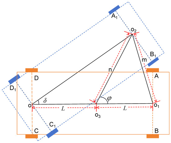
Figure 1.
Analysis chart of precursor angle parameters.
According to the geometric relationship in Figure 1, we can easily derive the relationship described by the following formula:
and according to Formula (2), there is the following relationship:
where m, n, and L denote their respective length meanings as shown in Figure 1. We let , , from Formula (3), then:
Next, we treat q as a constant in order to solve Equation (4) and derive the relationship between and . The unmanned vehicle moves in the counterclockwise direction. During the movement of the unmanned vehicle, the angle range will theoretically not exceed , so we do not consider the periodicity of . It takes in derivation and verification. We can solve Formula (4) to obtain the geometric relationship of as follows:
The advantage of placing the center of gravity at the rear-wheel center of the unmanned vehicle is that it is convenient for us to discuss and derive. In Figure 2, it can be seen that represents the angle between the vehicle body and the X-axis, so for this paper, should be the heading angle of the center drive. By substituting Equation (5) into Equation (1), the front-wheel-driving system of the unmanned vehicle is derived. Formula (5) can be used to apply the center-driving unmanned vehicle to front-wheel drive. It is the main innovation point of this paper. As illustrated in Figure 1, it depicts the relationship between the driving force of the unmanned vehicle and the front wheels. At the same time, it can optimize the impact when the center-of-mass point of the center driving is offset and closer to the rear wheels due to errors in the unmanned vehicle.
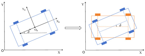
Figure 2.
Diagram of the connection between the rear wheel and the center.
We need to verify the feasibility of this front-wheel-drive vehicle model. For simplicity, will be used for the subsequent derivation process rather than . We need to explore whether unmanned vehicles can follow predetermined desired paths. Its key is to reflect the movement state of the unmanned vehicle. From a realistic perspective, we use the Cartesian coordinate system to simulate the application scenarios of unmanned vehicles. Then we establish a second coordinate system, , relative to the vehicle itself, as depicted in Figure 3.
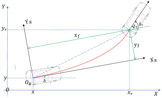
Figure 3.
Parameters and analytic diagram of unmanned vehicles.
Through the coordinate system, we can determine the position of the unmanned vehicle as . Its reference pose is . We need to set the reference trajectory equation for the target route and then make the unmanned vehicle move according to the desired trajectory. The target trajectory equation is given as
The principle of trajectory tracking is to build a dynamic model to predict future states and outputs. The position changes and output of unmanned vehicles are the focus of our efforts to achieve precise and stable control. Since the operation of the vehicle is a continuous dynamic process, various instances of interference will cause deviations between the expected and actual conditions of the unmanned vehicle. This difference is commonly referred to as the trajectory tracking error. By mapping the position information of the unmanned vehicle in the coordinate system to , its trajectory error vector can be determined. Furthermore, from the geometric relationship, the system error equation of the unmanned vehicle can be derived as
We aim to find a set of variables that play a controlling role, specifically setting the control variables as and to achieve synchronized trajectory tracking control of unmanned vehicles as accurately as possible. According to the trajectory error equation of the unmanned vehicle, a further derivative operation can be performed to obtain the dynamic error of the system.
Calculating the derivative of , one has
Similarly, can be expressed as
Therefore, the system dynamic error is deduced and the proof is completed:
The purpose of this paper is to set the appropriate control laws v and , as , such that , and the unmanned vehicle moves according to the desired trajectory, that is, . The block diagram of the unmanned vehicle control system is shown in Figure 4. The Lyapunov theory ensures the stability of the unmanned vehicle while guiding it along the desired trajectory. The difficulty lies in constructing a Lyapunov function and determining control variables. Next, the system control law we designed is given, and the derivation and proof process of the control law are explained.

Figure 4.
Block diagram of unmanned vehicle control system.
Theorem 1.
If the control variables of the unmanned driving system meet the following designed conditions
where and a, b, c, d are all constants greater than 0, then Equation (22) is negative and always holds, which satisfies the judgment condition of Lyapunov stability, which ensures that the system dynamic error Equation (12) approaches 0. It means that the dynamic error system is asymptotically stable and achieves the purpose of tracking the trajectory.
It is worth noting that in the virtual feedback variable (14), is a continuous bounded function with the control variable ω. When designing a control scheme during the movement process of the vehicle, such as turning, the relationship between speed and angular velocity must be considered, and the angular velocity has a significant impact on speed. The coordination relationship between speed and angular velocity is also a key issue to ensure stability. In Formula (13), the speed v is controlled by the angular velocity, and the angular velocity ω is also affected by v.
Proof of Theorem 1.
To design the trajectory tracker, we construct a dummy variable . It reduces the computational effort of designing a controller. The control system can convert the design goals into the desired output of the reference model, helping to improve control performance. We introduce a virtual feedback variable to enhance the performance and robustness of the system. It can analyze the controlled object’s output alongside the reference model’s output, enabling adjustments to enhance the dynamic performance and control accuracy of the control system. It can also reduce the impact of external interference and uncertainty and ensure that it can stably track the desired trajectory. The virtual feedback variable is introduced as
where .
Based on the virtual feedback variable, the Lyapunov function is constructed as
where . Obviously, .
Derive Formula (15) and substitute it into Formulas (12) and (14). The time derivative can be further calculated as
According to Formula (16), in order to make the time derivative of the Lyapunov function satisfy the condition of less than or equal to 0, we set the system control law to
where , . Then, we perform the derivative operation on , , and , resulting in the following derivatives:
It can be obtained from the Formulas (13) and (16), and its formula is
in which the constants a, b, c, and d are all greater than 0, and , so . Based on the principles outlined in Lyapunov theory, it has been demonstrated that the system exhibits asymptotic stability. From Lemma 1, it can be concluded that
The purpose of designing a feedback controller is to adjust the state variables through negative feedback within the system. It returns the system to equilibrium within a certain period of time. This adjustment process actually depends on the input signal of the controller, namely, velocity v and angular velocity . In the construction of the trajectory tracking controller, we introduced the idea of backstepping to determine the unknown parameter values in the controller. By applying Lyapunov stability theory and Barbalat’s lemma, we analyze the stability and asymptotic properties of nonlinear systems more comprehensively. It ensures that the system reaches a stable state after a period of time and enables the feedback controller to guide the unmanned vehicle along the desired trajectory. □
Remark 1.
Traditionally, unmanned vehicle systems have been analyzed at their center of mass because it facilitates discussion, derivation and verification. The center-driving model is used in many complex scenarios, such as logistics factories, factory workshops, etc. Debugging unmanned vehicles will waste a lot of manpower and material resources and will also affect production efficiency. Compared with center-driving unmanned vehicles, front-wheel driving is more flexible in steering and has smaller trajectory tracking errors. From the perspective of dynamic control and the Lyapunov stability theorem, this paper addresses the issue of side-slip angle production at the center of mass in front-wheel-driving systems. In Figure 1 and Equations (2)–(5), the center-driving model is transformed into a front-wheel-driving model, resolving the control challenges associated with front-wheel-driving unmanned vehicles. The control range of unmanned vehicles has been expanded, expanding the application scenarios of unmanned vehicles and making them closer to actual vehicles.
Remark 2.
In a control law for unmanned vehicles (13), the performance of the actual vehicle is constrained by the mechanical components and dynamics. Therefore, parameter selection plays a crucial role in achieving effective control and trajectory tracking. Through analysis, adjusting parameter a can affect X direction error. In addition, the parameter b ensures the local stability of the Lyapunov function component and plays a role in controlling the error. Therefore, parameter a and parameter b jointly control the error in the X direction. As they decrease, the error in the X direction becomes larger and the tracking trajectory becomes wider. Similarly, parameters a and c are the control quantities of Y direction error. However, in fact, we found that the main control quantity affecting Y direction error is parameter c. Decreasing the value of c causes the error along that axis to decrease, thereby improving convergence. Finally, the parameter d controls the angle error of the unmanned vehicle. Reducing the value of d will cause the angle error to increase and the angle change rate range to shrink, which will require longer time to adjust the angle to achieve convergence. The analysis of control variables will be further verified in the later experimental part. It is important to select appropriate values for these parameters to optimize control performance. Under appropriate values of controller parameters, better convergence results can be achieved based on the Lyapunov stability theorem.
Remark 3.
The front-wheel driving not only expands upon the center-driving configuration but also is advantageous in situations where center driving cannot adequately address errors. For example, during the movement of an unmanned vehicle, it is affected by force and causes an error when the driving force deviates from the center. Based on these problems, we derive the relationship (5), which plays an important role in expanding the model and reducing errors.
3. Simulation and Results
In this section, we simulate the proposed front-drive model using Matlab based on Theorem 1 from this paper. We present three trajectory tracking examples to verify the feasibility of the front-drive model. Example 1 simulates a spiral winding mountain road. We discuss the dynamic system error, tracking speed, and trajectory diagram during the tracking process of the unmanned vehicle. Example 2 involves simulating a circular road tracking trajectory. Notably, we investigate how different control parameters affect the controller’s performance under this circular trajectory. Specifically, we analyze the impact of various control parameters on trajectory tracking, as described in Remark 2. Finally, Example 3 features a comparative experiment involving three different drive forces: center drive, rear-wheel drive, and front-wheel drive. This example examines the effectiveness and stability of the controller under complex curves.
Table 1 lists the differences between the research objects of this paper and those in the studies [3,6,7,8,19,20,21,22,23,24,25,26,27,28,29,30,31,32], primarily reflecting variations in driving force and methods. Based on the backstepping method and Lyapunov stability theory, this paper proposes a method to extend the center drive to a front-wheel-drive system while ignoring the impact of the vehicle’s side slip during turns. Theoretically, this approach reduces the error caused by the deviation of the driving force from the center of mass. Research on front-wheel drive is the primary contribution of this paper. Additionally, when designing the controller using the Lyapunov function, the backstepping approach is essential. Analysis of Table 1 indicates that the main difference between our research and that of other scholars lies in the driving forces considered. Our analysis of the vehicle, with a focus on stability, demonstrates that the method and design process proposed in this paper are more comprehensive and reasonable.

Table 1.
Comparison of the capabilities and characteristics of unmanned vehicle tracking control.
Example 1.
In this example, we simulated the target trajectory of the vehicle as a bird’s-eye view of a winding mountain road. We expect that, in future research, AGVs will be able to move beyond factory operations to mountain operations and transportation, improving operational safety and reducing transportation costs. The spiral winding mountain road is a good choice for setting the target trajectory. To verify whether the method of extending the center drive to the front-wheel drive is effective under the control of the controller, we design the target trajectory shown in Figure 7. First, we assume there is a vehicle in operation, which we refer to as the target vehicle, and its trajectory is the target trajectory.
The conditions for the target vehicle are as follows: initial velocity , initial angular velocity , starting point , i.e., , , and initial angle . The trajectory of the tracking vehicle is called the practical trajectory. The conditions for the tracking vehicle are as follows: , , starting point , and initial angle . The controller parameters are as follows: . The target trajectory is set to . The simulation of vehicle trajectory tracking is based on the MATLAB experimental platform, with results shown in Figure 5, Figure 6 and Figure 7.
Figure 5 shows the dynamic system error of the unmanned vehicle, indicating that the distance between the target trajectory and the practical trajectory gradually decreases until they completely overlap. It can be observed that both the position error and heading angle error of the unmanned vehicle gradually decrease. Over time, the unmanned vehicle approaches the target trajectory until the error approaches 0, indicating that the unmanned vehicle has achieved synchronous tracking with the target trajectory. Figure 6 shows the speed changes of the target vehicle and the tracking vehicle, indicating that both vehicles maintain a constant speed after the trajectories overlap, reflecting synchronization between them. The tracking of the target trajectory and the practical trajectory is shown in Figure 7. The experimental results demonstrate that under the control of the proposed controller, the front-wheel drive of the unmanned vehicle can accurately track the trajectory and achieve synchronization once tracking is completed. This confirms the effectiveness of the controller and verifies the feasibility of the front-wheel drive. The unmanned vehicle system can achieve the desired synchronization and stability.
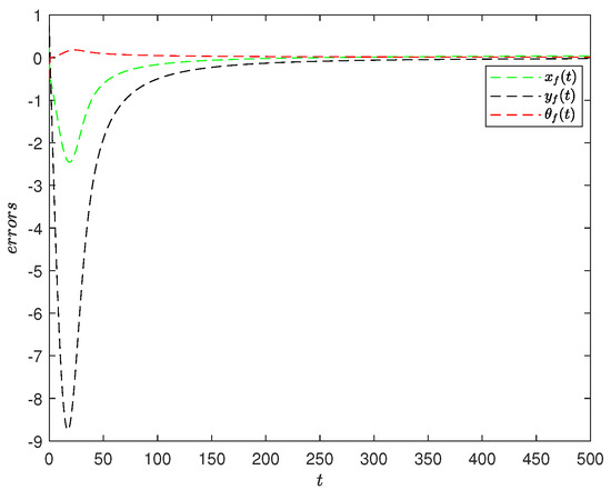
Figure 5.
The system error of the unmanned vehicle in example 1.
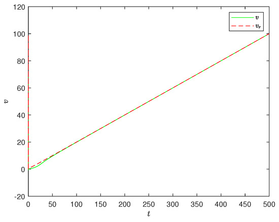
Figure 6.
The speed tracking of the unmanned vehicle in example 1.
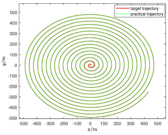
Figure 7.
The spiral synchronized trajectory tracking control in example 1.
Example 2.
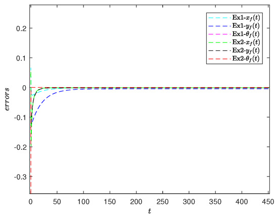
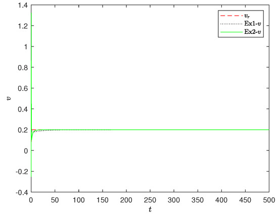
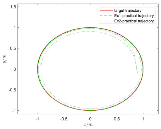
In this example, we simulate the performance of the unmanned vehicle in different environments by designing various target trajectories to explore the influence of controller parameters. The target equation for the circular trajectory set in the experiment is . The control parameters a, b, c, d are determined later. The other parameter conditions in this example are the same as those in Example 1, where the control parameters are set as . The experimental results shown in Figure 8, Figure 9 and Figure 10 indicate that these control parameters lead to better convergence under the circular trajectory and allow for faster tracking of the target trajectory. It is evident that the determination of parameters plays a decisive role in the effectiveness of the controller. To further investigate parameter determination, we discuss the control effects of these four parameters in the following experiment.

Figure 8.
Dynami errors of two parameters in example 1 and example 2 under circular trajectory.

Figure 9.
The speed changes of the two parameters in example 1 and example 2 under the circular trajectory.

Figure 10.
The two parameters in example 1 and example 2 are used in circular trajectory tracking.
In the above experiments, to further investigate the parameter determination problem, the following experiment discusses the control parameters listed in Table 2. We use the control variable method to set the parameters in four groups in which practical trajectory 1 serves as our base reference object. Refer to example 2 for better understanding. The comparison results of trajectory tracking with different parameters are given, as shown in Figure 11, Figure 12 and Figure 13. In Figure 11, the trajectory from 2 to 1, increasing the values of a and b, enhances the trajectory tracking performance. However, considering the excellent tracking performance of unmanned vehicles, further increasing the values of a and b becomes impractical. So here we choose to reduce the values of a, b to observe the comparison results. As can be seen in Figure 11, the tracking effect of practical trajectory 2 is worse than that of practical trajectory 1. As a and b increase, the convergence speed becomes faster. This error is mainly reflected in the X direction, as stated in Remark 2. In Figure 12, as c increases, the position in the Y direction is adjusted and the trajectory converges faster. For d, it represents the adjusted steering angle. Regarding the trajectory from 1 to 4, by reducing the value of variable d, the steering ability of the unmanned vehicle becomes worse. Its convergence speed becomes slower, its trajectory tracking ability becomes weaker, and it takes longer to achieve the tracking function. Control variables can be adjusted according to needs. Analysis of the experimental results shows that different parameter settings yield varying control effects on the unmanned vehicle. The determination of parameters is constrained by their interrelationships, making it crucial to design a suitable set of parameters for the controller.

Table 2.
Comparison of four different cases of synchronous tracking control parameters.
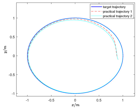
Figure 11.
Comparison of practical trajectories 1 and 2.
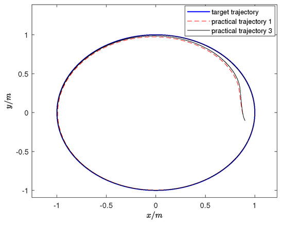
Figure 12.
Comparison of practical trajectories 1 and 3.
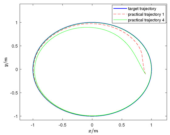
Figure 13.
Comparison of practical trajectories 1 and 4.
The main contribution of this paper is to establish a set of relationships for extending from center drive to front-wheel drive. To highlight the significance of our work, comparative experiments on different driving forces were conducted. We compared the front-wheel-driving system of the unmanned vehicle proposed in this paper with the rear-wheel-driving unmanned vehicle system in study [3] and the center-driving unmanned vehicle system in study [14]. Set the target trajectory as . Figure 14 shows that the front-wheel, rear-wheel, and center-driving modes can all achieve trajectory tracking control. The red curve represents the tracking trajectory of the front-wheel-driving system proposed in this paper. The blue curve represents the tracking trajectory of rear-wheel driving. The yellow curve is the center-driving tracking trajectory. Analysis of the detailed images in Figure 15 reveals that the tracking effect of center driving is significantly inferior to that of front-wheel driving. Due to the error of the driving force, the center driving exhibits a certain degree of deviation from the expected trajectory. Comparing front-wheel driving with rear-wheel driving, we can see that front-wheel driving can converge faster and then reach stability. This shows that front-wheel driving has better trajectory tracking. Similarly, comparing center driving with rear-wheel driving, we find that using center driving presents problems when the driving force is at the rear wheel. This further illustrates that the rear-wheel-driving unmanned vehicle system centered on the center of mass will produce certain errors. Therefore, it is necessary to propose a new driving method to avoid errors. This is also an advantage of our proposed method.
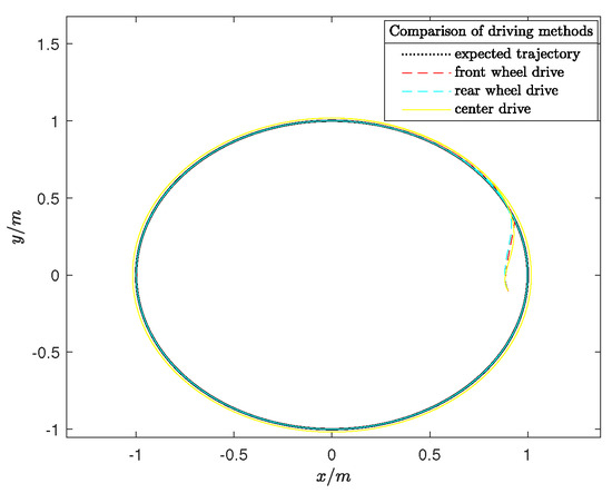
Figure 14.
Comparative analysis of trajectory tracking under different driving forces in Example 2.
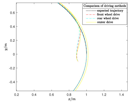
Figure 15.
Partial details in Figure 14.
Example 3.
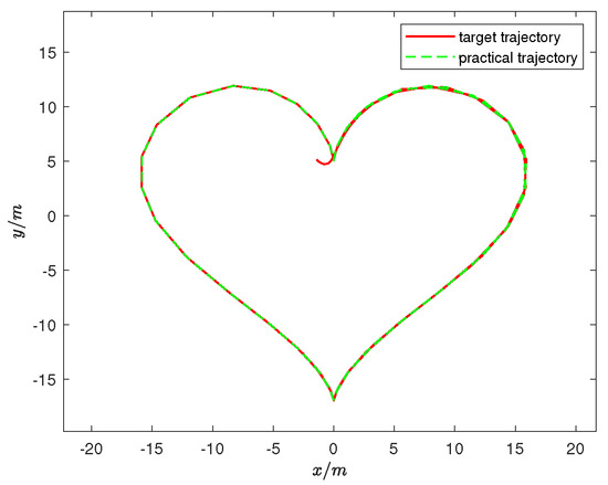
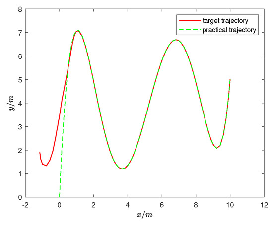
We believe that spiral and circular trajectories are too simplistic. To further explore the feasibility of the trajectory tracking controller for the unmanned vehicle, we use the Cartesian heart-shaped trajectory and a complex curve trajectory as experimental cases in Example 3. The polar coordinate expression of the Cartesian heart-shaped trajectory is , and the trajectory equation of the complex curve is . The controller parameters for the tracking vehicle were set to , and . The experimental results presented in Figure 16 and Figure 17 demonstrate that the unmanned vehicle can still achieve accurate and rapid tracking even when faced with relatively complex trajectories. The experiment in Example 3 further confirms the feasibility of the front-wheel-drive system under the controller’s action and ensures system stability based on Lyapunov stability theory, thereby expanding the potential for selecting driving forces.

Figure 16.
Cartesian heart-shaped trajectory tracking path diagram.

Figure 17.
Complex curve trajectory tracking path diagram.
4. Discussion
The unmanned vehicle is a highly nonlinear, strongly coupled, complex, dynamic system. The key to achieving trajectory tracking in an unmanned system lies in building the system’s dynamic error model and designing a controller. Based on the classic AGV model [18], this paper establishes the connection between the center drive and the front-wheel drive to study trajectory tracking control of the unmanned vehicle. In the simulation, the front-wheel-drive system of the unmanned vehicle successfully completes tracking on both a circular road and a complex curved road with multiple bends. The dynamic system error converges, the speed is consistent, and the trajectory diagram overlaps. The experimental results align with our theoretical expectations, verifying the feasibility and stability of the front-wheel-drive system. Compared with the study [3], we analyzed the tracking effect of different control parameters under circular trajectories, as shown in Figure 11, Figure 12 and Figure 13. However, we believe that the control parameters determined through system identification and experimental analysis are still not optimal, and there is room for improvement in parameter determination. Additionally, we conducted a comparative experiment for front-wheel drive, center drive [3], and rear-wheel drive [14]. The comparison results in Figure 15 indicate that the tracking effect and stability of front-wheel drive and rear-wheel drive are superior to those of center drive, with the front-wheel drive showing a faster convergence speed than the rear-wheel drive. Although the above discussion and experiments are theoretically feasible, there are still many challenges in actual working environments, such as the unpredictability of human-driven vehicles and complex speed variations. Future research must strengthen practical applications and further improve the model and control strategy to enhance trajectory tracking performance.
5. Conclusions
This paper studies the trajectory tracking problem of AGV unmanned vehicles based on Lyapunov stability theory. In order to overcome the difficulty of directly establishing a front-wheel-drive model, and in order to reduce the error caused by the center of mass offset due to side deviation and driving force during the movement of the center-drive unmanned vehicle, we proposed a method through geometric relationships to establish a connection between the center drive and the front-wheel drive. This method helps expand the center drive to the front-wheel drive, providing more possibilities for the selection of AGV driving force. In addition to high transmission efficiency and strong flexibility, front-wheel-drive vehicles also have simple structures, which can reduce costs for actual projects.
In the research process of this paper, we found that the problem of parameter determination in the controller is the most controversial point, and the parameter determination of this paper was to find a set of parameters with the best effect through system identification. We have already carried out relevant work on the issue of determining optimal parameters. In addition, the constraint problem of tracking speed is also our future research focus to solve complex speed changes. The problems of parameter determination and speed tracking are both areas that need to be improved in this paper and are also our research plans in the future.
Author Contributions
Conceptualization, Y.C., J.Z. and C.Z.; methodology, Y.C., J.Z. and C.Z.; software, Y.C. and C.Z.; validation, K.S. and E.C.; writing—original draft preparation, C.Z., J.Z. and Y.C.; writing—review and editing, Y.C., C.Z. and K.S.; visualization, J.Z.; investigation, Z.L.; supervision, K.S. and E.C.; funding acquisition, C.Z. All authors have read and agreed to the published version of the manuscript.
Funding
Our work in this paper was supported by the Guangdong Basic and Applied Basic Research Foundation (2021A1515110946), the Natural Science Foundation of Sichuan Province (2022NSFSC1822), the Key R&D Projects of Sichuan Provincial Department of Science and Technology (2023YFG0287), Sichuan Natural Science Youth Fund Project (2023NSFSC1366), and the National Engineering Research Center for Oil & Gas Drilling Equipment (202307).
Institutional Review Board Statement
Not applicable.
Informed Consent Statement
Not applicable.
Data Availability Statement
The data presented in this study are available on request from the corresponding author.
Conflicts of Interest
We have no conflicts of interest with any individual or organization regarding this paper.
Abbreviations
The following abbreviations are used in this manuscript:
| AGV | Automated Guided Vehicle |
| LSUV | Low-Speed Unmanned Vehicle |
| PID | Proportion Integration Differentiation |
| LC | Lyapunov control |
| o | The midpoint between wheels and |
| The midpoint between wheels A and B | |
| The midpoint between wheels and | |
| The midpoint between o and | |
| Virtual feedback variables implying and | |
| V | Lyapunov function |
| The derivative of the Lyapunov function |
References
- Zhang, Y.; Wang, W.; Wang, W.; Yang, C.; Zhang, Y. An adaptive constrained path following control scheme for autonomous electric vehicles. IEEE Trans. Veh. Technol. 2022, 71, 3569–3578. [Google Scholar] [CrossRef]
- Guo, N.; Zhang, X.; Zou, Y.; Lenzo, B.; Zhang, T. A computationally efficient path-following control strategy of autonomous electric vehicles with yaw motion stabilization. IEEE Trans. Transport. Electrific. 2020, 6, 728–739. [Google Scholar] [CrossRef]
- Shang, J.; Zhang, J.; Li, C. Trajectory tracking control of AGV based on time-varying state feedback. EURASIP J. Wirel. Commun. Netw. 2021, 2021, 162. [Google Scholar] [CrossRef]
- Maxwell, W.L.; Muckstadt, J.A. Design of automatic guided vehicle systems. IEEE Trans. 1982, 14, 114–124. [Google Scholar] [CrossRef]
- Kanayama, Y.; Nilipour, A.; Lelm, C.A. A locomotion control method for autonomous vehicles. In Proceedings of the 1988 IEEE International Conference on Robotics and Automation, Philadelphia, PA, USA, 24–29 April 1988; pp. 1315–1317. [Google Scholar]
- Pratama, P.S.; Gulakari, A.V.; Setiawan, Y.D.; Kim, D.H.; Kim, H.K.; Kim, S.B. Trajectory tracking and fault detection algorithm for automatic guided vehicle based on multiple positioning modules. Int. J. Control Autom. Syst. 2016, 14, 400–410. [Google Scholar] [CrossRef]
- Sánchez-Rodríguez, A.; Bayona, E.; Sierra-García, J.E.; Santos, M. Trajectory tracking nonlinear hybrid control of automated guided vehicles. Complexity 2024, 2024, 9514486. [Google Scholar] [CrossRef]
- Zhang, S.; Xia, Q.; Cheng, S.; Chen, M.; Xiao, G. Research on Lyapunov-based predictive path following control of AGV based on time constraint. Int. J. Control Autom. Syst. 2022, 20, 4005–4014. [Google Scholar] [CrossRef]
- Shi, L.; Li, W.; Shi, M.; Shi, K.; Cheng, Y. Opinion polarization over signed social networks with quasi structural balance. IEEE Trans. Automat. Control 2023, 68, 6867–6874. [Google Scholar] [CrossRef]
- Shi, L.; Liu, Q.; Shao, J.; Cheng, Y.; Zheng, W. A cooperation-competition evolutionary dynamic model over signed networks. IEEE Trans. Automat. Control 2023, 68, 7927–7934. [Google Scholar] [CrossRef]
- Shi, L.; Cheng, Y.; Shao, J.; Sheng, H.; Liu, Q. Cucker-Smale flocking over cooperation-competition networks. Automatica 2022, 135, 109988. [Google Scholar] [CrossRef]
- Shi, L.; Zheng, W.X.; Shao, J.; Chen, Y.H. Sub/super-stochastic matrix with applications to bipartite tracking control over signed networks. SIAM J. Control Optim. 2021, 59, 4563–4589. [Google Scholar] [CrossRef]
- Ibari, B.; Benchikh, L.; Elhachimi, A.R.H.; Ahmed-Foitih, Z. Backstepping approach for autonomous mobile robot trajectory tracking. Indones. J. Electr. Eng. Comput. Sci. 2016, 2, 478–485. [Google Scholar]
- Zhao, C.; Shi, K.; Tang, Y.; Xiao, J. Synchronized Tracking Control of Dynamic System of Unmanned Rear-Wheel Vehicles Based on Dynamic Analysis. Drones 2023, 7, 417. [Google Scholar] [CrossRef]
- Li, W.; Yu, S.; Tan, L.; Li, Y.; Chen, H.; Yu, J. Integrated control of path tracking and handling stability for autonomous ground vehicles with four-wheel steering. Proc. Inst. Mech. Eng. Part D 2023, 2023, 09544070231204249. [Google Scholar] [CrossRef]
- Hemami, A. A control scheme for low speed automated vehicles with double steering. In Proceedings of the 33rd IEEE Conference on Decision and Control, Lake Buena Vista, FL, USA, 14–16 December 1994; pp. 2452–2454. [Google Scholar]
- Bai, J.; Du, J.; Li, T.; Chen, Y. Trajectory tracking control for wheeled mobile robots with kinematic parameter uncertainty. Int. J. Control Autom. Syst. 2022, 20, 1632–1639. [Google Scholar] [CrossRef]
- Zhu, X.X.; Chen, N.J.; Yin, B.G. Design and analysis of AGV path correction controller. Technol. Innov. Appl. 2017, 12, 62–63. [Google Scholar]
- Kanayama, Y.; Kimura, Y.; Miyazaki, F.; Noguchi, T. A stable tracking control method for an autonomous mobile robot. In Proceedings of the IEEE International Conference on Robotics and Automation, Cincinnati, OH, USA, 13–18 May 1990; pp. 384–389. [Google Scholar]
- Jiang, B.; Li, J.; Yang, S. An improved sliding mode approach for trajectory following control of nonholonomic mobile AGV. Sci. Rep. 2022, 12, 17763. [Google Scholar] [CrossRef]
- Azzabi, A.; Nouri, K. Design of a robust tracking controller for a nonholonomic mobile robot based on sliding mode with adaptive gain. Int. J. Adv. Robot. Syst. 2021, 18, 1729881420987082. [Google Scholar] [CrossRef]
- Ling, Y.; Wu, J.; Lyu, Z.; Xiong, P. Backstepping controller for laser ray tracking of a target mobile robot. Meas. Control 2020, 53, 1540–1547. [Google Scholar] [CrossRef]
- Mai, T.A.; Dang, T.S.; Duong, D.T.; Le, V.C.; Banerjee, S. A combined backstepping and adaptive fuzzy PID approach for trajectory tracking of autonomous mobile robots. J. Braz. Soc. Mech. Sci. Eng. 2021, 43, 156. [Google Scholar] [CrossRef]
- Ma, G.; Ghasemi, M.; Song, X. Integrated powertrain energy management and vehicle coordination for multiple connected hybrid electric vehicles. IEEE Trans. Veh. Technol. 2017, 67, 2893–2899. [Google Scholar] [CrossRef]
- Zhang, K.; Su, R.; Zhang, H.; Tian, Y. Adaptive resilient event-triggered control design of autonomous vehicles with an iterative single critic learning framework. IEEE Trans. Neural Netw. Learn. Syst. 2021, 32, 5502–5511. [Google Scholar] [CrossRef] [PubMed]
- Yang, L.; Zhang, W.; Wang, H. Study on Trajectory Tracking Control of Two-Wheel Difference Speed of AGV. Softw. Eng. Appl. 2017, 6, 59–67. [Google Scholar]
- Cui, M.; Liu, H.; Liu, W.; Qin, Y. An adaptive unscented kalman filter-based controller for simultaneous obstacle avoidance and tracking of wheeled mobile robots with unknown slipping parameters. J. Intell. Robot. Syst. 2018, 92, 489–504. [Google Scholar] [CrossRef]
- Ye, H.; Wang, S. Trajectory tracking control for nonholonomic wheeled mobile robots with external disturbances and parameter uncertainties. Int. J. Control Autom. Syst. 2020, 18, 3015–3022. [Google Scholar] [CrossRef]
- Pourboghrat, F.; Karlsson, M.P. Adaptive control of dynamic mobile robots with nonholonomic constraints. Comput. Electr. Eng. 2002, 28, 241–253. [Google Scholar] [CrossRef]
- Mutoh, N. Front-and-rear-wheel-independent-drive-type electric vehicle (FRID EV) with compatible driving performance and safety. World Electr. Veh. J. 2009, 3, 17–26. [Google Scholar] [CrossRef]
- Mutoh, N.; Ustunomiya, T.; Akashi, H.; Tastuoka, S. Braking control method for front-and-rear-wheel-independent-drive-type electric vehicles (FRID EVs) on low-friction-coefficient roads. In Proceedings of the 2010 IEEE Vehicle Power and Propulsion Conference, Lille, France, 1–3 September 2010; pp. 1–6. [Google Scholar]
- Klančar, G.; Matko, D.; Blažič, S. A control strategy for platoons of differential drive wheeled mobile robots. Robot. Auton. Syst. 2011, 59, 57–64. [Google Scholar] [CrossRef]
Disclaimer/Publisher’s Note: The statements, opinions and data contained in all publications are solely those of the individual author(s) and contributor(s) and not of MDPI and/or the editor(s). MDPI and/or the editor(s) disclaim responsibility for any injury to people or property resulting from any ideas, methods, instructions or products referred to in the content. |
© 2024 by the authors. Licensee MDPI, Basel, Switzerland. This article is an open access article distributed under the terms and conditions of the Creative Commons Attribution (CC BY) license (https://creativecommons.org/licenses/by/4.0/).