Abstract
The emergence of pathological manifestations on facades persists globally, with recurring failures occurring often due to repeated construction details or design decisions. This study selected a building with a recurring architectural design and evaluated the stain pattern on its facade using a UAV with an infrared thermal camera. The results showed that advanced technology offers a non-invasive and efficient approach for comprehensive inspections, enabling early detection and targeted interventions to preserve architectural assets without requiring ancillary infrastructure or risking workers at height. The precise identification of damage clarified the real causes of the observed pathological manifestations. Capturing the images allowed accurate inspection, revealing hollow and damp spots not visible to the human eye. Novel results highlight patterns in the appearance of dirt on facades, related to water flow that could have been redirected through proper geometric element execution. The presented inspection methodology, staining standards, and construction details can be easily applied to any building, regardless of location. Sills, drip pans, and flashings must have drip cuts, adequate inclination, and projections to prevent building degradation.
Keywords:
UAV; unmanned aerial vehicle; facade; stains; infrared thermography; damage map; inspection 1. Introduction
Civil construction’s main objective is to ensure its occupants’ safety and protection against environmental agents. Facades are crucial in this regard, serving as protective barriers that vertically surround built structures [1]. Facade cladding systems serve a dual purpose: they protect buildings against aggressive environmental agents [2] and enhance their visual appeal, thereby contributing to property value and aesthetics.
Numerous studies have concentrated on facade systems, where most of the pathological manifestations of buildings occur [3]. This system is particularly susceptible to environmental aggression and harsh weather conditions, such as driving rain. Additionally, the high degradation rate of facades may be attributed to various factors, including design flaws, low-quality materials, and the absence or inadequacy of maintenance practices, all of which compromise their performance [4].
Understanding the severity of this damage is crucial, as it can affect structural integrity, aesthetic appeal, and watertightness [2]. In this way, several pathological manifestations on facades have been identified through inspection processes by several studies, including geometric cracks, mapped fissures, peeling, mold, stains due to accumulation of dirt, efflorescence, specters or ghosts, and peeling paint [5,6,7].
Souza et al. [8] affirm that the regions with the largest areas of degradation in the building are the corners and borders, continuous walls, and top regions, representing approximately 86% of the degradation. Frequently minor deteriorations, such as stains, are neglected due to their minimal impact on facades. However, with the aging process and exposure to actual environmental conditions, these deteriorations can escalate into severe degradation, such as coating detachment [9].
Stains, or dirt, are one of the most frequently observed in buildings, which denote, among other causes, a lack of maintenance [10]. They can be classified into various types depending on the origin [11]: efflorescence, carbonation, uniform or non-uniform dirt, “ghost-like”, moisture, fungi, parasitic vegetation, corrosion, chromatic changes, graffiti, and birds’ droppings.
Therefore, carrying out periodic inspections is essential to maintaining the adequate performance of this construction system. The Brazilian standard NBR 15575-1 [12] outlines performance criteria for residential buildings, offering guidelines for evaluating facade systems based on aspects such as water tightness, durability, maintainability, and aesthetic and environmental performance.
Madrigal et al. [13] highlight the economic significance of building maintenance, emphasizing its role in sustaining the construction industry’s growth. A building with pathologies experiences functional deficiencies, compromising safety and performance standards [14]. Hence, understanding the root causes, including material quality, structural misuse, and inadequate maintenance, is crucial for effective mitigation. Classification of facade irregularities is pivotal in recommending appropriate remedial actions, as outlined by the Brazilian standard NBR 16.747 for building inspections [15].
The most critical point for maintaining the useful life of buildings is maintenance, with buildings that are easier to inspect and maintain resulting in higher estimated service lives. Among the most critical characteristics for the impact on service life are the distance from pollution sources and the facade orientation [16]. In this way, an adequate methodology to maintain this system is necessary and is proposed by the authors in [10].
Construction details significantly influence facade performance, with errors in design or execution leading to infiltration, cracks, cladding detachment, and structural damage [17]. Thus, meticulous attention to detail during the design and construction phases is essential to ensure the longevity and functionality of facades.
Conventional methods require significant mobilization of equipment and labor to effectively conduct maintenance and accurately assess facade damage, including identifying its causes and the agents influencing its occurrence. Beyond the costs associated with this mobilization, it is crucial to highlight the risks involved in working at heights.
In this regard, the use of advanced equipment, such as the UAV’s use in building inspections, when compared to conventional methods, is an alternative [18,19] to overcome problems such as financial viability, as it speeds up the process and reduces work safety costs, as it facilitates inspections in places that are difficult to access. On facades, for example, the equipment’s use eliminates the need to hire scaffolding and rockers, which not only generates significant savings but also helps to minimize the risks to worker safety and the inconvenience to building users [20].
Even though this inspection procedure is not yet standardized, several authors have published studies on the subject, seeking to develop a method for carrying out these inspections. Combined with the use of UAVs and infrared thermography, the automatic diagnosis of pathological manifestations has been developed through deep learning that has been obtained through research [21,22]. The authors also highlight the need for scientific research to validate these methods [23].
Given these considerations, building managers must recognize the critical importance of assessing the condition of facade systems to ensure their continued functionality [24]. It is also important to develop peculiar procedures for building types and locations, and to replicate and improve such UAV technology processes. To this end, this study employs UAV technology equipped with infrared thermography to identify recurring damage to facades of a building. There is a gap in the literature about the damage patterns and their solutions, so the building chosen for this study has typical patterns, allowing the obtained information to be applied to similar buildings that present the same problems, and where timely repair will prevent further damages that will improve building aesthetics and service functions.
2. Literature Review
The UAV’s use in facade inspections can be utilized with other techniques, such as infrared thermography. Infrared thermography, known as TI or TIR, converts the infrared radiation emitted by an object. Using thermography, the radiation emitted by a body, which is invisible to the human eye because of its wavelength, can be translated into detailed images of the visible object and the surface temperature profile. This method reveals the presence of hidden structures, anomalies, faults, and/or irregularities by recognizing the infrared radiation’s intensity from the object, translated into color images (thermograms) in a non-destructible way [25].
Many methods have been studied to apply infrared thermography to building pathology inspection [26,27,28]. These images and the analysis of their temperature gradients can clearly show the type of damage suffered by a building under the right conditions, by considering the correct measurement of temperatures, which is strongly linked to the material emissivity value. Since this is a sensitive technique, in addition to the skill of the professional, the influences of the environment and the materials must be taken into account.
Domingues [29] highlights, for example, the importance of being careful with neighboring buildings with mirrored facades, as these mirrors can cause alterations in the thermogram readings. In addition, the researcher recommends paying attention to cloudy days with no solar radiation, as in this case, the heat emissivity of the surface may not be sufficient for clear and accurate results. Considering that the emissivity, surface reflectivity, and atmospheric attenuation of the material are the main factors influencing the thermography technique, the authors of [30] suggest that the best times of day to apply the technique are in the early morning or early evening when the outside temperature is lower and little direct solar radiation on the facade will be inspected. The authors also highlight dirt on the surface of the cladding as a possible cause of changes in the emissivity recorded by the equipment, so proper mapping of the conditions of the facade can avoid or help to avoid mistakes in the results.
Another relevant aspect that influences the results is the need for direct observation of the thermal image without obstacles between the radiation source being studied and the display, even if they are opaque, partially opaque, or transparent in the visible range, which can inhibit or misinterpret the discovery of the fault [31]. Additionally, the quality of thermal images can be affected by image capture distance, temperature, position of the sun, characteristics of the ceramic plates, edge effects, and the influence of reflections [19].
Therefore, a flight plan must be drawn up to obtain high-quality images when inspecting facade damage using UAVs. In general, the roadmap for carrying out inspections consists of a preliminary analysis of the building, then completion of a checklist and other tasks, including image collection, image processing, and identification of pathological manifestations [20,32,33,34,35,36].
The general characteristics of the building must be analyzed, identifying locations that may favor the emergence of pathological manifestations or that may pose a risk to the aircraft’s flight during image capture, such as the presence of trees or elements that hinder connection with the equipment, as well as locations with heavy vehicle or pedestrian traffic [32]. Some documents that can be used in this analysis are architectural plans, facade plans, as-built plans, and, if available, previous inspection reports [33]. Measures must comply with current flight regulations, and an operational risk assessment must be carried out by the person responsible for the flight [32].
To ensure safe aircraft operation, a checklist must be followed, covering battery and remote-control charging, weather conditions such as wind speed and rain probability, and all required flight documents [34]. Specifically, it is recommended to reserve approximately one-third of the battery’s capacity for takeoff, landing, and emergency maneuvering. Additionally, the cell phone attached to the remote control should be fully charged. Before the flight, the equipment should be powered on to verify that no pending software updates need to be installed. If an SD card is being used, ensure it is formatted and correctly inserted into the device. Lastly, confirm that all necessary flight permissions have been obtained.
To ensure that the images are obtained in the best possible way, it is recommended that the capture direction be parallel to the largest side of the facade, as well as ensure an overlap of images between 60% and 80% of the perpendicularity between the camera and the surface to be studied [36], especially to reproduce the building in 3D models. The main advantages of the images are that they can be processed manually or by software that facilitates the location of pathological manifestations, and that the holistic view of the object of study is provided [35].
Another possibility is the identification of pathological manifestations through video recordings, which are reproduced in slow motion and repeated whenever the professional inspector considers it necessary so that each point of the object of study can be carefully analyzed for symptoms of anomalies and the occurrence of pathological manifestations [20].
Together, these advanced technologies offer a non-invasive and efficient approach to diagnosing recurring issues in typical facades. By understanding the root causes of pathological manifestations, professionals can develop effective strategies to mitigate future occurrences, providing long-term durability and integrity to buildings.
3. Methods
The methods consisted of six stages, as demonstrated in Figure 1’s flowchart.
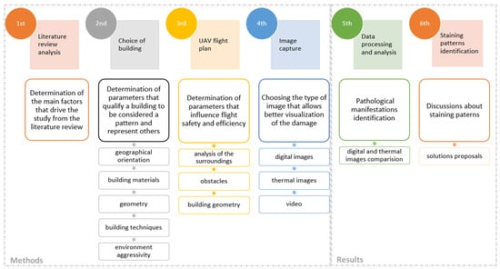
Figure 1.
Flowchart of the study’s stages.
The first stage consists of a literature review analysis on the subject to acquire the necessary knowledge to determine the main factors driving the study, then stages 2 to 6 were planned and carried out as explained in the following items.
3.1. The Choice of Building
A building representing local civil construction was chosen, opting for construction systems commonly used in the study area. Thus, the chosen building should have a reinforced concrete and masonry construction system and should have facade cladding with mortar and/or ceramic, with paint or texture. Additionally, it would be interesting for the study if the building had a “blind” facade, facades with moldings, the presence of construction details on the facade such as drip pans, and exposure to different geographic orientations and climatic conditions. As the study focused on stain analysis, a facade that presented this type of damage was also chosen. Being exposed to the urban environment in a high-traffic area was also one of the requirements for the study object to be representative.
The building chosen is a multi-family residential building with 30 apartments, located in the city of Rio de Janeiro, that was built around 1986 and has a rectangular site with a depth of 44.0 m, a width of 9.5 m, 4 facades, and a setback at the west facade. Figure 2 illustrates the top view of the building, identifying the solar orientation and setback position (sides A and B), and each building facade is represented in Figure 3. The south facade is the main building facade.
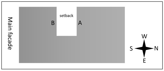
Figure 2.
The top view of the building, identifying the solar orientation and setback position.
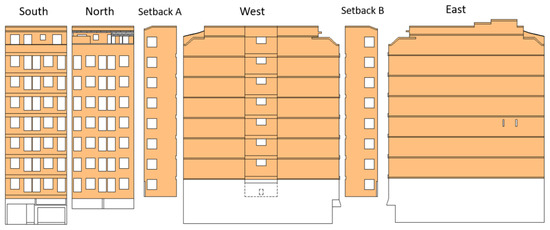
Figure 3.
The Building facade views.
It is a typical building for the studied area, with 9 floors distributed between common areas and apartments. It represents conventional civil construction systems, with a structure made of reinforced concrete and ceramic brick sealing masonry, and it is covered by mortar with mostly painting and a partial finish of ceramic tiles. Figure 4 shows the views of the building’s facades, obtained using a digital camera.
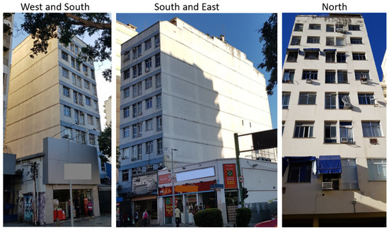
Figure 4.
Digital camera images of the building’s studied facades.
3.2. UAV Flight Plan
A flight plan was developed for the UAV covering the entire facade area, as its trajectory was to capture pathologic manifestations that were already identified and others. At this stage, the surroundings of the building were analyzed, checking for the presence of trees, obstacles, and neighboring buildings. It was observed that very close neighboring buildings would prevent inspection at the base of some facades. Additionally, safe locations where the UAV could land were identified.
The equipment used to take the images in this study was the Mavic 2 Enterprise Dual model, manufactured by DJI. VANT has several features that made it easier to conduct the study, such as the obstacle detectors’ presence in all directions and the onboard thermographic camera. It is a multi-rotor drone, considered ideal for building inspections due to its maneuverability and ability to hover in the air. In addition, this model is capable of recording digital and thermographic images at the same time, saving time and battery power.
Figure 5 represents the flight plan applied to the facade images’ capture. The direction in which images were captured was recommended by Ballesteros and Lordsleem [36], following the vertical bands for the videos (slimmer facades) and the horizontal bands for the photographs (wider facades). During the flight, no reference points were fixed; the camera was kipped perpendicular to the facade, and it was ensured that the entire facade was completely recorded.
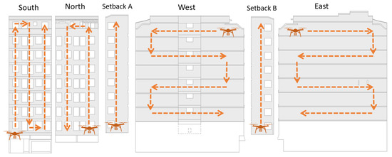
Figure 5.
The VANT flight plan.
3.3. Image Capture
The image capture was carried out through a visit to the studied building, where UAV flight execution was performed. Digital and thermal data were captured using high-resolution video and images. Images were captured by photographing the building after stabilizing the UAV at specific points by video frame. In all cases, the UAV was flown as normal, without autonomy, by programming the trajectory to be followed and with the help of the equipment’s obstacle detection tools.
These images were organized in a database, which enabled comparative visual analysis between digital and thermal images. Additionally, the videos were analyzed at a low speed, making it possible to identify the location of the points of interest for the study.
It is worth emphasizing that in certain facades it was impossible to capture images of the bottom of some facades because of the neighboring buildings. This can be seen as a limitation of UAV usage, as its obstacle sensors, designed for safety, prevent close inspection near obstacles.
3.4. Data Processing and Analysis
The high-resolution images and videos, both digital and thermal, were analyzed using Microsoft 2024 photo and video visualizers software’s to survey the main damages present on the facades. Since the photos and videos were of high resolution, it was only possible to make the diagnosis by zooming in on them. These damages were then represented on a damage map of the building facades to illustrate them and provide an overview of the building’s deterioration and the areas where they were most concentrated. The damage map was developed in AutoCAD 2023 software, creating hatching and colors for each type of damage represented on the facades.
3.5. Staining Patterns Discussion
After analyzing the main locations of the stains observed on the facades, digital and thermal images were used to identify the causes and outline prevention strategies. The discussion was based on previous studies from the literature review, seeking solutions applicable to all buildings that fit the same geometry pattern as the building studied.
4. Results and Discussion
This section presents damage maps as well as digital and thermographic images, in addition to analyses and discussion of the obtained results.
4.1. Damage Maps
The damage maps of all the facades are presented in Figure 6, where damage identified through UAV inspection were depicted. A different color represents each instance of damage, and it was observed that the most prevalent damage was staining. Other pathologic manifestations were identified, including on the east facade, the “blind” facade, where the presence of specters throughout its area, also known as “ghosting”, occurred along with a significant number of cracks. Cracks, peeling paint, and disaggregation of coat mortar were also observed with minor frequency.
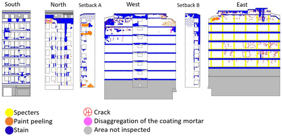
Figure 6.
Damage Maps.
4.2. Analysis of the Staining Patterns
As was seen in the damage maps, staining was present in several parts of the facades. Through the images obtained with the UAV and analyzing the damage map, it was possible to observe that the stains had some patterns, and were most frequently located in specific points. Stains due to dirt accumulation were found below the window openings on all the facades with this construction element. It was also noted that this pathological manifestation occurred more frequently on the ventilation prism facades, probably due to insufficient solar incidence combined with bad sill dimensioning, either due to inadequate lateral inclination or transposition of the drip rails. Also, stains were more visible at the top of the buildings, where wind-driven rain is more frequent.
There is a consistent tendency for buildings to experience higher incidences of damage at the top, compared to intermediate regions. In many studies, dirt predominates on the facades, regardless of geographic orientation, with a notably higher occurrence on the south facade [37].
There was a large deposition of dirt below the windowsills, as shown in the VANT digital and thermographic images presented in Figure 7. This observation was a recurrent pattern in several buildings and clearly represents a frequently observed type of damage that occurs due to poor execution or absence of sills, that allows water to flow into the facade, carrying dirt and impregnating moisture and dirt. According to Silva and Torres [38], all horizontal surfaces tend to accumulate trash and dust which will later be washed away by rainwater, however, the amount of this dirty water that will reach the vertical surfaces of the walls depends on the geometry of the horizontal surfaces.

Figure 7.
The (a) digital and (b) thermographic images of the staining above the windows.
The thermographic image in Figure 7 highlights the humidity above the sill, attesting to the inefficiency of this construction detail.
Figure 8 also shows the staining on the south facade, which has ceramic cladding. It was possible to observe the concentration of dirt at the point where the sills joined the wall and at the edges of the sill because of the lack of lateral trespassing in the masonry.

Figure 8.
The staining in the sill joins (a) and at the edges (b) of the sill at the facade South coated by ceramic.
The flow of water on the facades is directly related to dirt. Several authors [39,40,41] have been studying how water flow occurs on facades in addition to the influences of wind-driven rain, height of buildings, and the surroundings to understand this behavior. It is known that points where water is deposited with greater intensity are favorable for the deposition of dirt, such as soot from cars, and also create environments conducive to the proliferation of microorganisms that need moisture to develop.
The insertion of construction details, such as drip pans, is recommended to expulse the water in the facade, preventing its accumulation. However, when these elements are poorly dimensioned, they can generate the opposite result, serving as a point of accumulation of dirt and water and resulting in stains such as those observed on the drip pans in the facades on the east and the west setback of the studied building, shown in Figure 9.
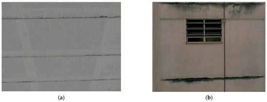
Figure 9.
The staining by dirt accumulation in the facade’s drip pans: (a) east facade; (b) west setback.
The “ghost-like” staining or specters in the East facade were also observed and are presented in Figure 9a. These stains are normally associated with hygrothermal problems on the walls and characterized by non-uniform dust deposition on the wall, allowing the visualization of the bricks and the structure from color differentiation, and in the most acute cases, dirt stains and microorganism colonization [11].
There was also a recurring concentration of dirt on the top of the building, specifically on the flashings and copings of the walls. According to research carried out by Blocken et al. [42], the wetting pattern of the facades was highly non-uniform. However, it could be stated that the edges and upper corners were the regions that received the greatest intensity of wind-driven rain. The shape of the building, such as height and width, as well as the intensity of the wind river rain also influence the exposure of the building to water flow; this explains why, for example, the lower part of taller buildings receives little water flow [43].
Figure 10 presents the VANT digital images (a) and thermography (b) images of dirt at the top of the building. The dirt concentration and, consequently the moisture, is presented in the thermography images, where some red points were also observed that suggested the coating’s detachment due to hot air pockets (hollow).
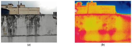
Figure 10.
The dirt on the top of the building, specifically on the flashings and copings of the walls: (a) digital image; (b) thermographic image.
4.3. Solutions Proposal
The geometry of the construction elements and the presence of the dripping pans below the sills, flashings, and copings, and along the facade are essential for adequate performance. There is little research and consensus about these elements’ ideal dimensions and geometries. Still, there are some usual recommendations, such as having inclinations and projections on the facade to improve the water runoff speed and inlaying the sill laterally into the masonry, in addition to the use of dripping pans below the elements to help drain the water and prevent it from running down the wall.
Silva [44] recommends for sills to have a drop of 8%, be recessed into the sides by at least 2 cm, have an advance front of at least 2 cm, and have dripping pans 5 mm deep below the sill. Zuccheti [45] assessed the influence of dimensions, inclinations, and the drip’s presence on water flow from the facade. The author concluded that larger lateral projections result in a greater protected area beneath the windowsill for the study parameters. Regarding the frontal projection, the 5 cm projection showed the most effective displacement of rainwater, protecting the underside of the windowsill. The 6% inclination also provided superior protection for the area beneath the windowsill compared to the 20% inclination for sills with lateral embedment.
Silva and Torres [38] and Robinson and Baker [6] demonstrate that water flows and drains together by inserting the drip pan into the sill, preventing it from returning to the facade. If the upper profile of the sill has a sharp edge, the water flow divides again and is contained by the drip pan.
By compiling recommendations to obtain better windowsill performance and avoid the appearance of stains and moisture problems around frames, Figure 11 presents a recommended geometry for its implementation. Figure 11a represents the sill as a whole and its installation in the window; Figure 11b presents the sill in section.
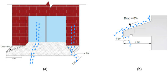
Figure 11.
Windowsill recommendation: (a) installed in the window; (b) sill in section.
Robinson and Baker [6] suggested a different solution for transferring runoff from one set of control surfaces to the next: precast protective panels for facades. Nowadays, precast details are common in facades, but the same observations made for the sill also concern the drip pans over the facades; they must have a drop of about 8%, a projection of about 5 cm from the coating surface, and a drip to cut the water flow.
Drip pans used on the facades exposed to the environment must follow similar recommendations to those of the sills, including an inclination and projection relative to the final finish of the coating. They must also have a dripper on their underside to facilitate water removal and expulsion from the facade. Advice for these elements is the same as those shown in Figure 11b, that is, with an 8% drop, a water drip, and a frontal advance of at least 5cm.
To solve the problems of water stains on parapets, walls, and low walls in general, it is possible to use caps with drips with geometries similar to those of sills, as shown in Figure 12.
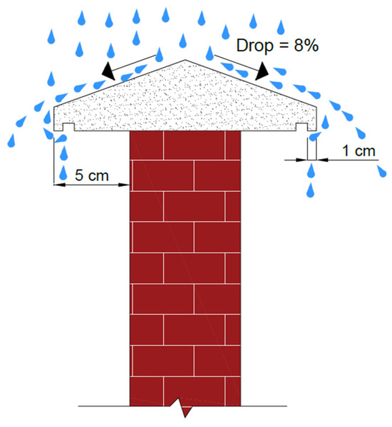
Figure 12.
The caps with drips for parapets, walls, and low walls.
Finally, self-cleaning coatings can be utilized to prevent stains on facades and ensure that all details have adequate geometry. Many studies [46,47,48] have been conducted on these coatings and some industries offer them commercially. These coatings prevent water and dirt from depositing on facades, expelling them from the surface.
5. Conclusions
This study aimed to use UAVs and infrared thermography to facilitate the diagnosis of recurrent pathological manifestations on the facades of multi-story buildings. As stains were the most common pathological manifestation, the focus was on evaluating their causes and proposing technical solutions to avoid them. Considering the applied methodology, as well as the equipment used, the following conclusions were reached:
- (a)
- The use of UAVs was extremely efficient for the visual inspection of the facade, allowing the visualization of pathological manifestations in hard-to-reach areas without the needs for large equipment and subjecting workers to work at height;
- (b)
- Images obtained with infrared thermography allow the identification of moisture presence and possible points of coating detachment;
- (c)
- The presented building is representative of the staining pattern on the facades of other buildings, allowing the identification of staining which are constantly repeated in different buildings. This took the geographical position and the presence or absence of windows into account for influencing the staining pattern observed on building facades;
- (d)
- The main causes of staining on facades are related to the absence or poor execution of construction details, such as sills, dripping pans, and drips, thus a design of sill is proposed to prevent staining below windows, with proper drop, projection, and lateral embedment;
- (e)
- Staining located on the parapet walls of buildings is related to the lack of flashings with drip edges. The protection of these elements and the disruption of the water flow can be prevented with adequate geometries of the drip pan design, as suggested.
This research thus provides valuable insights by focusing on a building type that is representative of a broad spectrum of structures employing similar formats and construction techniques. By diagnosing and discussing the primary reasons behind the emergence of stains, this study contributes significantly to understanding such issues. It also sheds light on the limitations encountered during the survey of pathological manifestations, such as the restricted range of UAVs.
For the scientific community, conducting direct studies on the inspection and diagnosis of pathological manifestations in buildings by utilizing advanced equipment is essential. Such endeavors can serve as a foundational database for comparing conservation conditions identified and exploring the potential relationships between different scenarios.
Regarding the practical application of this work, these findings serve as benchmarks for both conforming and non-conforming buildings constructed using similar patterns. This information is invaluable for guiding professionals in making informed decisions regarding the design and maintenance. However, further research in this field is imperative to develop new technologies that can streamline the diagnosis of pathological manifestations. This can be achieved by integrating computational tools and automated pattern recognition systems.
Author Contributions
Conceptualization, J.A.d.S.F., F.R.L.C., J.A.O.A. and C.G.; methodology, J.A.d.S.F.; investigation, J.A.d.S.F., F.R.L.C., J.A.O.A. and C.G.; data curation, J.A.d.S.F., F.R.L.C., J.A.O.A., C.G., C.M.S. and M.A.; writing—original draft preparation, F.R.L.C., J.A.O.A. and C.G.; writing—review and editing, C.M.S. and M.A.; supervision, C.M.S., M.A. and A.N.H.; funding acquisition, A.N.H. All authors have read and agreed to the published version of the manuscript.
Funding
This research was funded by the Carlos Chagas Filho Foundation for Research Support of the State of Rio de Janeiro-FAPERJ: 2022—E-26/200.342/2023(281755).
Data Availability Statement
The original contributions presented in the study are included in the article, further inquiries can be directed to the corresponding author.
Acknowledgments
The authors thank the Universidade Federal do Rio de Janeiro and the FAPERJ—Fundação Carlos Chagas Filho de Amparo à Pesquisa do Estado do Rio de Janeiro.
Conflicts of Interest
The authors declare no conflicts of interest.
References
- ABNT (ASSOCIAÇÃO BRASILEIRA DE NORMAS TÉCNICAS). NBR 15575-4: Residential Buildings—Performance. Part 4: Requirements for Internal and External Vertical Sealing Systems; ABNT: Rio de Janeiro, Brazil, 2021. (In Portuguese) [Google Scholar]
- Bauer, E.; Piazzarollo, C.B.; de Souza, J.S.; dos Santos, D.G. Relative importance of pathologies in the severity of facade degradation. J. Build. Pathol. Rehabil. 2020, 5, 7. [Google Scholar] [CrossRef]
- Carretero-Ayuso, M.J.; Rodríguez-Jiménez, C.E.; Bienvenido-Huertas, D.; Moyano, J.J. Interrelations between the types of damages and their original causes in the envelope of buildings. J. Build. Eng. 2021, 39, 102235. [Google Scholar] [CrossRef]
- Pereira, C.; De Brito, J.; Silvestre, J.D. Contribution of humidity to the degradation of façade claddings in current buildings. Eng. Fail. Anal. 2018, 1, 103–115. [Google Scholar] [CrossRef]
- Vallejo, F.J.L. Contamination of Stone Facades by Atmospheric Pollution: The Case of Valladolid. Spain. Inf. Construcción 1990, 41, 45–72. [Google Scholar] [CrossRef][Green Version]
- Robinson, G.; Baker, M.C. Wind-Driven Rain and Buildings; National Research Council Canada, Division of Building Research: Ottawa, ON, Canada, 1975. [Google Scholar] [CrossRef]
- Quintela, M.A. Durability of Exterior Wall Coatings in Single-Layer Plaster. Master’s Thesis, Faculdade de Engenharia da Universidade do Porto, Porto, Portugual, 2006. (In Portuguese). [Google Scholar]
- de Souza, J.S.; Bauer, E.; Nascimento, M.L.; Capuzzo, V.M.; Zanoni, V.A. Study of damage distribution and intensity in regions of the façade. J. Build. Pathol. Rehabil. 2016, 1, 3. [Google Scholar] [CrossRef]
- Gaspar, P.L.; Brito, J. Quantifying environmental effects on cement-rendered facades: A comparison between different degradation indicators. Build. Environ. 2008, 43, 1818–1828. [Google Scholar] [CrossRef]
- Madureira, S.; Flores-Colen, I.; Brito, J.; Pereira, C. Maintenance planning of facades in current buildings. Constr. Build. Mater. 2017, 147, 790–802. [Google Scholar] [CrossRef]
- Flores-Colen, I.; Brito, J.; Freitas, V.P. Stains in facades’ rendering—Diagnosis and maintenance techniques’ classification. Constr. Build. Mater. 2008, 22, 211–221. [Google Scholar] [CrossRef]
- ABNT (ASSOCIAÇÃO BRASILEIRA DE NORMAS TÉCNICAS). NBR 15575-1: Residential Buildings—Performance. Part 1: General Requirements; ABNT: Rio de Janeiro, Brazil, 2024. (In Portuguese) [Google Scholar]
- Madrigal, L.O.; Lanzarote, B.S.; Bretones, J.M.F. Proposed method of estimating the service life of building envelopes. Rev. Construcción (J. Constr.) 2015, 14, 60–68. [Google Scholar] [CrossRef]
- Ventura, M.; Dias, I.S.; Flores-Colen, I.; Silva, A. Pathology and proactive maintenance of floor finishes. Int. J. Build. Pathol. Adapt. 2023, 41, 588–605. [Google Scholar] [CrossRef]
- ABNT (ASSOCIAÇÃO BRASILEIRA DE NORMAS TÉCNICAS). NBR 16747: Building Inspection—Guidelines, Concepts, Terminology and Procedure; ABNT: Rio de Janeiro, Brazil, 2020. (In Portuguese) [Google Scholar]
- Bourke, K.P.; Silva, A.; Gaspar, P.L. Application of Service Life Planning to Existing Buildings—Perspectives on Condition Appraisal, Performance and Cost. In Proceedings of the XVI International Conference on Durability of Building Materials and Components DBMC, Beijing, China, 10–13 October 2023. [Google Scholar]
- Moch, T. Interface between Mitre/Masonry and Their Around: Typical Pathological Manifestations’ Analysis and Solutions’ Proposals. 178 f. Master’s Thesis (Master in Engineering), Universidade Federal do Rio Grande do Sul, Porto Alegre, Brazil, 2009. [Google Scholar]
- Ribeiro, D.; Santos, R.; Cabral, R.; Calçada, R. Remote Inspection and Monitoring of Civil Engineering Structures Based on Unmanned Aerial Vehicles; Chastre, C., Neves, J., Ribeiro, D., Neves, M.G., Faria, P., Eds.; Advances on Testing and Experimentation in Civil Engineering. Springer Tracts in Civil Engineering; Springer: Cham, Switzerland, 2023. [Google Scholar] [CrossRef]
- Melo, S.B.; Da Paz, R.F.; Mesquita, E. Recent advances on infrared thermography for ceramic tiles detachments diagnosis: Literature review. J. Build. Pathol. Rehabil. 2024, 9, 35. [Google Scholar] [CrossRef]
- Falorca, J.F.; Miraldes, J.P.N.D.; Lanzinha, J.C.G. New trends in visual inspection of buildings and structures: Study for the use of drones. Open Eng. 2021, 11, 734–743. [Google Scholar] [CrossRef]
- Woo, H.-J.; Hong, W.-H.; Oh, J.; Baek, S.-C. Defining Structural Cracks in Exterior Walls of Concrete Buildings Using an Unmanned Aerial Vehicle. Drones 2023, 7, 149. [Google Scholar] [CrossRef]
- Munawar, H.S.; Ullah, F.; Heravi, A.; Thaheem, M.J.; Maqsoom, A. Inspecting Buildings Using Drones and Computer Vision: A Machine Learning Approach to Detect Cracks and Damages. Drones 2022, 6, 5. [Google Scholar] [CrossRef]
- Ruiz, R.D.B.; Lordsleem Júnior, A.C.; Fernandes, B.J.T.; Oliveira, S.C. Unmanned Aerial Vehicles and Digital Image Processing with Deep Learning for the Detection of Pathological Manifestations on Facades. In ICCCBE 2020: 18th International Conference on Computing in Civil and Building Engineering, São Paulo, Brazil, 18–20 August 2020; Santos, E.T., Scheer, S., Eds.; Lecture Notes in Civil Engineering; Springer: Cham, Switzerland, 2021; Volume 98. [Google Scholar] [CrossRef]
- Attia, S. Adaptive Facades Performance Assessment, Interviews with Facade Experts; International report; SBD Lab: Liege, Belgium, 2019. [Google Scholar] [CrossRef]
- Richter, T.; Fouad, N.A. Guidelines for Thermography in Architecture and Civil Engineering, 1st ed.; Birkhauser: Basel, Switzerland, 2021; 176p. [Google Scholar]
- Fox, M.; Coley, D.; Goodhew, S.; De Wilde, P. Time-lapse thermography for building defect detection. Energy Build. 2015, 92, 95–106. [Google Scholar] [CrossRef]
- Fox, M.; Goodhew, S.; De Wilde, P. Building defect detection: External versus internal thermography. Build. Environ. 2016, 105, 317–331. [Google Scholar] [CrossRef]
- Balaras, C.A.; Argiriou, A.A. Infrared thermography for building diagnostics. Energy Build. 2002, 34, 171–183. [Google Scholar] [CrossRef]
- Domingues, A.P. Identification of Pathological Manifestations on Building Facades with Ceramic Coating, Using the Infrared Thermography Technique. 29 f. Bachelor’s Thesis, Universidade Católica de Brasília, Brasília, Brazil, 2015. (In Portuguese). [Google Scholar]
- Freitas, S.S.; Freitas, V.P.; Barreira, E. Detection of façade plaster detachments using infrared thermography A nondestructive technique. Constr. Build. Mater. 2014, 70, 80–87. [Google Scholar] [CrossRef]
- Santos, L. Classification and Modeling of Influencing Factors on Thermographic Inspections in Homeless Environments. Ph.D. Thesis, (Doctorate of Science in Electrical Engineering), Universidade Federal de Itajubá, Itajubá, Brazil, 2012; 160p. (In Portuguese). [Google Scholar]
- Entrop, A.G.; Vasenev, A. Infrared drones in the construction industry: Designing a protocol for building thermography procedures. Energy Procedia 2017, 132, 63–68. [Google Scholar] [CrossRef]
- Seo, J.; Duque, L.; Wacker, J. Drone-enabled bridge inspection methodology and application. Autom. Constr. 2018, 94, 112–126. [Google Scholar] [CrossRef]
- IBAPE-MG (Brazilian Institute of Engineering Assessments and Expertise ff Minas Gerais). Recommended Practice for Building Inspection, Precautionary Inspection and Engineering Expertise Using UAVs; IBAPE-MG: Belo Horizonte, Minas Gerais, Brazil, 2019. (In Portuguese) [Google Scholar]
- Faust, L.C. Facade Analysis with UAV Aerial Survey. Bachelor’s Thesis (Bachelor of Civil Engineering), Universidade Católica de Brasília, Palhoça, Brazil, 2019. (In Portuguese). [Google Scholar]
- Ballesteros, R.D.; Lordsleem Junior, A.C. Unmanned Aerial Vehicles (UAVs) for inspection of pathological manifestations on facades with ceramic coating. Ambiente Construído 2021, 21, 119–137. (In Portuguese) [Google Scholar] [CrossRef]
- Verdum, G.; Bersch, J.D.; Guerra, F.L.; Socoloski, R.F.; Giordani, C.; Zucchetti, L.; Masuero, A.B. Mortar coating degradation in historical buildings facades from Rio Grande do Sul—Brazil. Constr. Build. Mater. 2021, 310, 125221. [Google Scholar] [CrossRef]
- Silva, J.M.; Torres, M.I. Deficiencies in the performance of sills in protecting facades against the action of water. In PATORREB—2003: 1º Encontro Nacional sobre Patologia e Reabilitação de Edifícios; FEUP: Porto, Portugal, 2003. (In Portuguese) [Google Scholar]
- Chew MY, L.; Tan, P.P. Facade staining arising from design features. Constr. Build. Mater. 2003, 17, 181–187. [Google Scholar] [CrossRef]
- Van Den Brande, T.; Blocken, B.; Roels, S. Rain water runoff from porous building facades: Implementation and application of a first-order runoff model coupled to a HAM model. Build. Environ. 2013, 64, 177–186. [Google Scholar] [CrossRef]
- Yoo, C.; Cho, E.; Na, W.; Kang, M.; Lee, M. Change of rainfall–runoff processes in urban areas due to high-rise buildings. J. Hydrol. 2021, 597, 126155. [Google Scholar] [CrossRef]
- Blocken, B.; Derome, D.; Carmeliet, J. Runoff from Building Facades: A Review. Build. Environ. 2013, 60, 339–361. [Google Scholar] [CrossRef]
- Blocken, B.; Carmeliet, J. The influence of the wind-blocking effect by a building on its wind-driven rain exposure. J. Wind Eng. Ind. Aerodyn. 2006, 94, 101–127. [Google Scholar] [CrossRef]
- Silva, R.A. Mortar Facade Cladding Project: The Issue of Construction Details. Bachelor’s Thesis (Bachelor of Science in Civil Engineering), Universidade Federal do Rio Grande do Sul, Porto Alegre, Brazil, 2011; 64p. (In Portuguese). [Google Scholar]
- Zucchetti, L. Influence of Sill Characteristics on Wetting of Walls Close to Windows in the Face of Directed Rain. Ph.D. Thesis, Programa de Pós-Graduação em Engenharia Civil da Universidade Federal do Rio Grande do Sul, Porto Alegre, Brazil, 2016; 172p. (In Portuguese). [Google Scholar]
- Dodiuk, H.; Rios, P.F.; Dotan, A.; Kenig, S. Hydrophobic and self-cleaning coatings. Polym. Adv. Technol. 2007, 18, 746–750. [Google Scholar] [CrossRef]
- Qualharini, E.L.; Stolz, C.M.; Martini, M.; Polesello, E.; Da Silva, C.R. Self-Cleaning Mortar Façades with Addition of Anatase and Rutile Titanium Dioxide for Cool Façades. Energies 2023, 16, 1874. [Google Scholar] [CrossRef]
- Reddy, N.A.; Panchangam, S.C. Evaluation of self-cleaning performance of TiO2-intermixed and TiO2-coated cement mortars under natural sunlight. J. Sustain. Cem.-Based Mater. 2024, 13, 1032–1049. [Google Scholar] [CrossRef]
Disclaimer/Publisher’s Note: The statements, opinions and data contained in all publications are solely those of the individual author(s) and contributor(s) and not of MDPI and/or the editor(s). MDPI and/or the editor(s) disclaim responsibility for any injury to people or property resulting from any ideas, methods, instructions or products referred to in the content. |
© 2024 by the authors. Licensee MDPI, Basel, Switzerland. This article is an open access article distributed under the terms and conditions of the Creative Commons Attribution (CC BY) license (https://creativecommons.org/licenses/by/4.0/).