1. Introduction
For UAVs, it is necessary to enhance their autonomy [
1,
2], which enables them to independently process various sensitive information, assess the current situation, and make plans or predictions for current and future tactical missions [
3]. An autonomous mission planning system is an important support for improving the operational effectiveness of the precision guidance of weapons and UAVs [
4,
5]. As one of the core and main functions of mission planning, autonomous flight path planning is an essential technology developed along with modern information technology, and is widely used in various types of aircraft.
In addition to ensuring the ability to fly to the destination, the autonomous planning system of UAVs also needs to avoid obstacles, enemy radars, and no-fly zones along the path, and its own maneuverability needs to meet the corresponding requirements [
6,
7]. Therefore, the planning course can be divided into two levels. On the one hand, it is required to quickly search the feasible and safe paths in the space. On the other hand, it needs to make sure that the UAVs are able to track the path according to the desired path instructions [
8].
For the path planning problem, each algorithm has its own strengths and shortcomings. Common algorithms include: A* [
9], D* [
10,
11], dynamic programming algorithm, intelligent algorithms [
12,
13], etc. The rapidly-exploring random tree (RRT) algorithm considers the non-holonomic constraints of the aircraft, has fast planning and convergence speeds, does not require system modeling or geometric division of the search area, has high coverage of the search space, and explores unknown areas as much as possible, providing a new approach to solving path planning problems. However, based on RRT, the RRT* algorithm has made improvements and obtains a relatively optimal solution, but it still has some shortcomings, such as low efficiency and too random of an expansion process. To further develop the search efficiency and obtain a more optimized solution of RRT*, various papers have been studied and developments made. In [
14], for the sake of having better planning results, it adopts a sampling method, such as Gaussian distribution sampling, and the local bias sampling method is also considered. Ref. [
15] takes the artificial potential field into consideration and combines it with the RRT* algorithm to generate biased random states and improve the rate of convergence. Literature [
16] adopts the potential function so as to sample the nodes randomly to expand new nodes; therefore, it can shorten the search time. Literature [
17] proposes a search for the nearest neighbor to expand new nodes, and [
18] uses a greedy heuristic to explore the environment rapidly based on the heuristic sampling of the path expansion region. In [
19,
20,
21], they all utilize the two-way search strategy, that is, grow the forward tree and backward tree at the same time to improve the search speed.
Only completing the planning part cannot guarantee that the aircraft can track the flight path. Therefore, path tracking should be further considered to guarantee that the aircraft is able to accomplish the flight mission according to the designed waypoint instructions. At present, the most widely used method is MPC control [
22,
23,
24]. In [
25], the least square method is used to track the waypoints, and applying the predictive control to develop the path tracking performance in the horizontal range. In [
26], the sliding mode control is combined with MPC to guarantee optimal performance control of the system under various constraints. In [
27], the MPC controller based on Lyapunov input constraint (LMPC) solves the trajectory tracking problem. There are also other methods such as robust control [
28], vector field control, and so on. Literature [
29] proposes a controller that is robust to cope with the model uncertainty and measurement noise to develop the control accuracy. Literature [
30] proposes a hybrid gradient vector field algorithm to guide UAVs to complete the planned 3D path.
Path planning and trajectory tracking are two essential applications for controling military and civilian UAVs. However, it could be concluded from the above investigations that the research is usually based on the separation of path planning and trajectory tracking design, and only a few studies integrate these two technologies simultaneously [
31]. At present, most algorithms in the literature only focus on the path planning level, that is, to complete the search in space and design the path instruction information, without verifying the realization of flight.
Considering the practical application of engineering, based on our previous work [
32], this paper effectuated waypoint planning based on the DB-RRT* algorithm to optimize the waypoints and further extract the key points information. Unlike other path-tracking algorithms, the “offline design + online flight” scheme is adopted. The guidance law with angle constraint is devised to guide the vehicle to fly online on the basis of waypoints’ instructions so that it can reach the destination autonomously. It is worth mentioning that the part of the path planning has been involved in our previous work [
32]. However, to ensure the integrity of the problem statement and framework, this part is summarized and polished further, and still presented in this paper.
Aiming at the existing problems, the autonomous flight technology of UAVs is studied in this paper. The main contributions are as follows:
The sliding mode guidance technology based on angle constraints with finite-time convergence is devised, and its stability and finite-time convergence properties are proved. Through the proposed guidance law, not only the aircraft can reach the specified point at any angle in space, but also the convergence time of the whole process is guaranteed.
In this paper, the trajectory tracking problem is effectively transformed into a guidance problem with angle constraints. The guidance law based on sliding mode with angle constraint can make the vehicle achieve all-around angle arrival, so as to ensure that the aircraft can realize path tracking according to the waypoint information in different directions. The sliding mode guidance law has the property of finite convergence, which can ensure that the tracking time is convergent during trajectory tracking.
To address the challenge posed by the separation of path planning and trajectory tracking techniques found in existing literature, this paper proposes a solution using the “offline planning + online flight” strategy. By integrating both path planning and trajectory tracking, this approach enables the autonomous flight of aircraft and facilitates the automation and intelligence of these vehicles.
The framework of this article is shown below.
Section 2 establishes the environmental modeling and describes the DB-RRT* algorithm to generate and optimize the waypoints.
Section 3 deduces the sliding mode autonomous flight guidance technology based on angle constraints with finite-time convergence, and the stability proof is given. The simulation results are displayed in
Section 4, and the results illustrate the priority and feasibility of the proposed algorithm and the scheme. At last,
Section 5 provides the conclusions.
2. Waypoint Generation Technology Based on Improved DB-RRT* Algorithm
2.1. Environment Modeling
Modeling of emerging threats in the flight environment is a prerequisite for path planning. In this paper, the stochastic function method is utilized to describe the environmental information, which is suitable for simulating the terrain contour in a large range. This paper mainly analyzes the three aspects of radar detection, weapon threat, and no-fly zone constraint encountered during flight. It is worth mentioning that to pay more attention to the details of the proposed technology, the application is limited to the static one.
Radar threat:
The shape of radar detection is analogously regarded as a cone. The coordinates of the radar in space are
, that is, the vertex of the cone. According to the geometry, a cross-section in the two-dimensional plane is able to be roughly reckoned as a circle, where the radius of the circle
can be defined as:
in which,
is the detection angle of the radar.
Weapon threat:
The launching point of all kinds of weapons is denoted as
, whose attack range is approximately regarded as half a sphere, that is, the center of the corresponding sphere. The threat model function is expressed as:
and
is the field of fire. The shape of these threats is also shown as a circle in the two-dimensional plane.
No-fly zones:
The general shape of the no-fly zones is usually not certain. When the UAV is in a no-fly zone, the probability that it will be damaged is generally considered to be 1. Thus, UAVs are not allowed to enter the no-fly zone.
2.2. The Improved DB-RRT* Algorithm
The DB-RRT* method is adopted in this paper. Our team has conducted research on this part before, and the specific content of this algorithm can be found in literature [
32]. A flow chart of the DB-RRT* algorithm is displayed in
Figure 1.
The main innovations of this algorithm are as follows. Firstly, the original RRT* algorithm is ameliorated to improve the efficiency and success rate of the planning. Secondly, the DB-RRT* algorithm is further proposed, which combines improved-RRT* with the DBSCAN algorithm, and the contingency and randomness of single planning of the RRT* algorithm are both overcome. In this way, the path generated by the DB-RRT* algorithm is more optimized and has high reliability, improving the safety of the autonomous flight of aircraft. More importantly, the waypoints obtained by this method do not need further operation and modification, which can be directly used as inputs for the following waypoint tracking mission, providing technical support for the autonomous flight tasks of UAVs.
To guarantee the integrity of the technical framework proposed in this paper, the content involved in the DB-RRT* algorithm is briefly explained below.
The RRT* algorithm has some improvements in the optimization performance of planning results in contrast with the RRT method, but it still has the problem of low search efficiency due to the strong randomness of node selection. Using the RRT* algorithm may require searching the entire search space, which requires a large amount of calculation and affects the time of searching feasible paths. Therefore, in consideration of the disadvantages of the RRT* algorithm, such as a large amount of computation, and low search efficiency, this section takes practical application scenarios into consideration and develops the RRT* algorithm.
In response to the above problems, RRT* is improved from the following aspects:
Set the target attraction;
Set the dynamic adaptive step size;
Add physical constraints;
Add evaluation function.
After the improvement of the RRT* algorithm, the path generation is faster and more efficient. However, due to the occasionality and randomness of a single planning of the RRT* algorithm, it is difficult to directly apply this method to engineering practice. Therefore, a series of waypoints planned based on the RRT* algorithm should be further optimized to overcome its shortcomings and promote the reliability of planning. The improved RRT* algorithm can quickly generate several suitable paths that can reach the specified point without additional operations of the data source. According to these planning results, a database can be generated, and then the DBSCAN algorithm is introduced for clustering algorithm analysis to obtain a path with high reliability and better performance [
33,
34].
DBSCAN is a representative density-based clustering algorithm. It defines clusters by the larger density of connections between points, rather than simply by distance. Its fundamental principle makes it very suitable for analyzing densely distributed data points and discovering clusters of arbitrary shapes from noise, overcoming the limitations of KMeans, BIRCH, and other algorithms that only apply to convex sample sets.
The DBSCAN algorithm calls for two essential input parameters: the radius and the minimum number of points . Select an unvisited point in the database as the starting point, and find all points within a distance less than or equal to . If the number of points is not less than the minimum number , the current point and its nearby points form a cluster, and the starting point is marked as visited. Process all unvisited points within the same cluster in the same way to complete the expansion of the cluster. If the number of nearby points is less than the , temporarily mark it as a noise point and look for the next point. Repeat the above steps until all points in the database are classified into a cluster or marked as noise.
The DBSCAN algorithm is utilized to perform statistics and cluster optimization on the waypoint information in a large number of path data. Consequently, the key information that affects the success of path planning can be extracted, so that the optimized waypoint information can be obtained.
Remark 1. According to different task requirements, the evaluation function in the RRT* algorithm can be adjusted, so that task constraints can be considered in the planning process and the corresponding path to meet the requirements can be generated. The evaluation function selected in this paper is to choose the shortest path.
Remark 2. To further improve the safety performance and reliability of the autonomous flight of the UAV, when the DB-RRT* algorithm is employed for waypoint extraction, appropriate assessment criteria can be further added to examine the obtained waypoint information and evaluate the feasibility. The assessment criteria mainly adopted in this paper include two aspects. Firstly, the safety performance of the extracted waypoints is considered. Traditionally, it is known that the planned path will be safer if it is farther away from obstacles. Secondly, the smoothness and transitional performance of the waypoints between each other is taken into account. Generally, it is more reasonable to reduce changes in vehicle velocity direction.
2.3. The Improved DB-RRT* Algorithm Flow
The algorithm flow is summarized as follows.
Input: Starting coordinates, target coordinates, environmental information;
Step 1: Utilize improved-RRT* to generate the paths that constitute the database;
Step 2: Based on the database, use the DBSCAN algorithm to analyze and extract the clustering point;
Step 3: Through the assessment criteria evaluate whether the waypoints meet the requirements;
Step 4: If they meet the requirements, then the new path is generated, otherwise repeat steps 2 to 3.
3. Sliding Mode Autonomous Flight Guidance Technology Based on Angle Constraints with Finite-Time Convergence
The improved DB-RRT* path planning algorithm provides a scattered set of waypoints, which are a series of time-independent points existing in space. Due to the constraints of aircraft dynamics, overload, and maneuvering ability, the route instructions directly connected with waypoints cannot be put into use in the actual flight scenario.
Therefore, a sliding mode control strategy based on angle constraints [
35,
36] is devised in this section so that the aircraft can be controlled autonomously according to the planned waypoints and it can be guaranteed to converge within a certain time to complete the guidance [
37].
3.1. Model Transformation Analysis
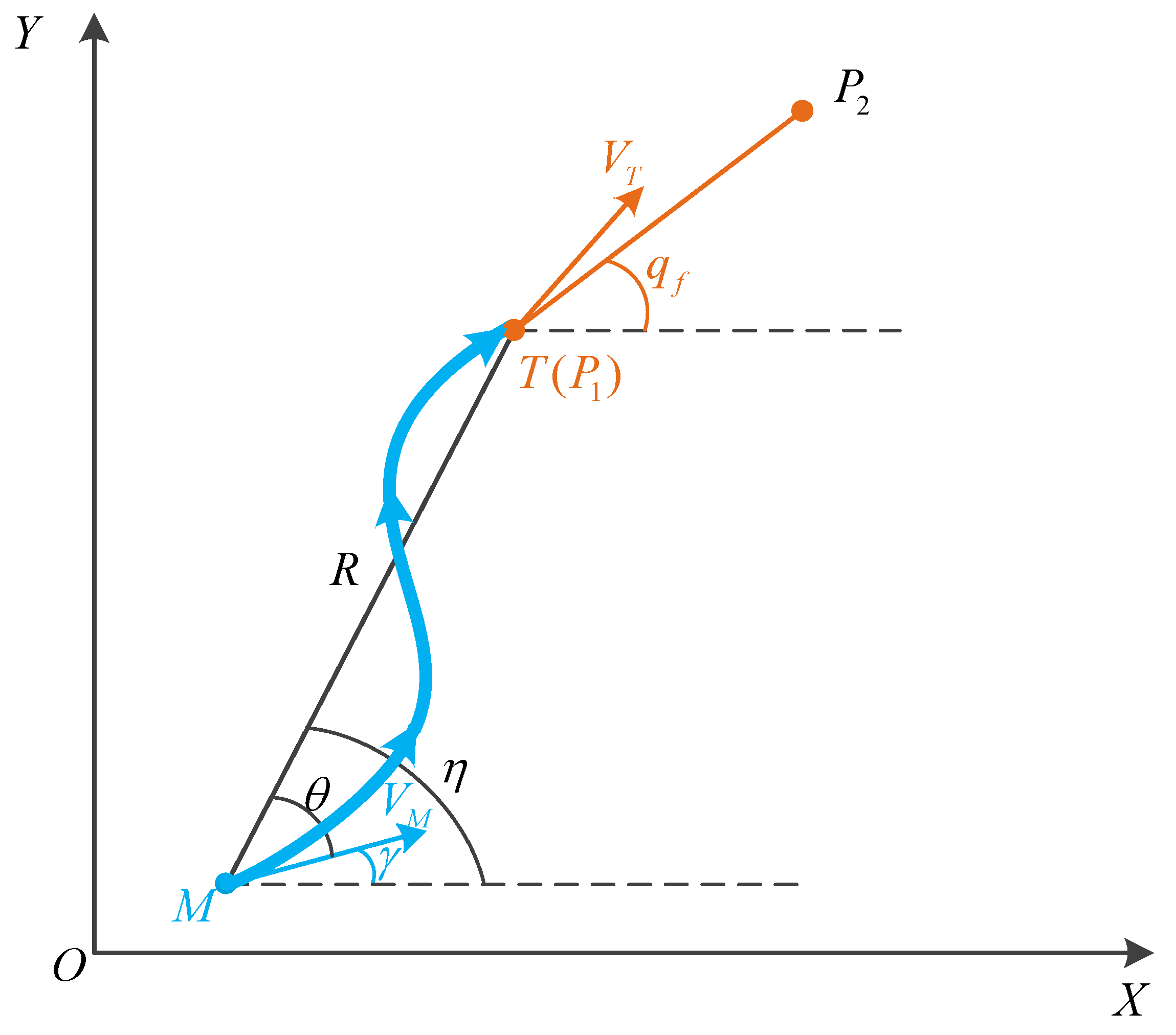
This section intends to devise the guidance strategy with angle constraints, leading the UAV to fly according to the waypoints’ instructions, and use the planned waypoints’ information to guide the aircraft to complete the flight path and obtain a safe trajectory to the target point. As shown in
Figure 2, the global waypoint information is known. During each process,
and
are the waypoints for the next two moments. The angle between the vector
and the
X-axis is denoted as
—that is the angle constraint. It is worth noting that when the UAV arrives at the last goal point, the vector angle is obtained by connecting the current waypoint and the target point.
The relative distance between the current position M and the next waypoint (T) is denoted as R. is the line of sight (LOS) angle, which is defined as rotating counterclockwise from the reference line and turning to the target line in a positive direction. is regarded as the leading angle. In the horizontal plane, is reckoned as the trajectory deflection angle; however, in the vertical plane, is reckoned as the trajectory inclination angle. In order to distinguish the different states, the subscripts T and M represent the relevant information of the waypoint in the next moment and the current information, respectively. Correspondingly, is denoted as the current velocity of the UAV, and is the UAV’s velocity of the next moment.
Combined with the path planning scenario, it can be assumed that
, and
is a constant. The motion equation of the aircraft moving from
M to
could be listed as:
in this equation, corresponding with the above description,
is the current leading angle,
is the current trajectory deflection angle and
is the current LOS angle.
Based on the above model, for the purpose of ensuring the convergence of the flight process, a sliding mode control strategy with finite time convergence is designed to guide the UAV.
3.2. Design of Sliding Mode Guidance Based on Angle Constraint with Finite-Time Convergence
According to the Equation (
3), the relative normal velocity along the LOS between the UAV and the goal is recorded as
, which can be expressed as follows [
38]:
Taking the derivative of Equation (
4), we obtain:
where
is regarded as the control input instruction. Therefore, the designing course of the guidance law can be described according to the design control input instructions, so that the following formula is established:
Define the sliding mode variables:
in which,
is the required angle constraint. Further, there are:
Through designing
, the UAV meets
before reaching the target point. Thus, Equation (
6) is true. Define:
For
, it should be:
So the designing goal is to construct
to satisfy the above inequality. Thus,
can be noted as:
and
is a small positive number. When
, because of the existence of
, it can be guaranteed that
is bounded. Differentiating Equation (
9), we obtain:
According to the literature [
39], we can define the following Barrier Lyapunov function:
where,
Additionally, the following equation should be established:
where,
According to the theory of sliding mode control, it can be known that only when
will meet the convergence condition and the design requirement. Therefore,
is chosen as:
where
and
are parameters. The control results can be adjusted by regulating the parameters. Moreover, the instruction is able to ensure that the designed guidance law can converge in a finite time.
3.3. Stability Analysis
Theorem 1. Assume that there exists continuous positive definite function , which is a function of variable x, and meets the following inequality:among them, , . Then, the system will converge to the equilibrium point in a finite time, and time T satisfies the following inequality: Theorem 2. If , then the Lyapunov function defined by Equation (13) satisfies: In combination with (
10), there is:
Meanwhile, there is also:
Above all, is bounded and is negative, so there is always a finite time where is true.
From Equations (
8) and (
24), it can be seen that:
Integrating both sides:
which means,
This demonstrates that when , there must be and .
can be further expressed as:
where,
According to Theorem 1, B will converge in finite time, which means that the sliding mode variable S can converge to 0 in finite time.
4. Simulation and Results
4.1. Simulation Results of Waypoints Optimization Based on Improved DB-RRT* Algorithm
Presume an existing 10,000 m × 10,000 m plane, set the starting point coordinates as
, and the target point coordinates as
. The other parameters can be checked in the literature [
32]. The different configurations in the simulation scenes can be equivalent to the obstacles, radar detection range, threats, or no-fly zones encountered during flight. During the planning process, UAVs need to find a flight path that meets the mission indicators and poses the least risk in the environment of threats and flight risks.
According to
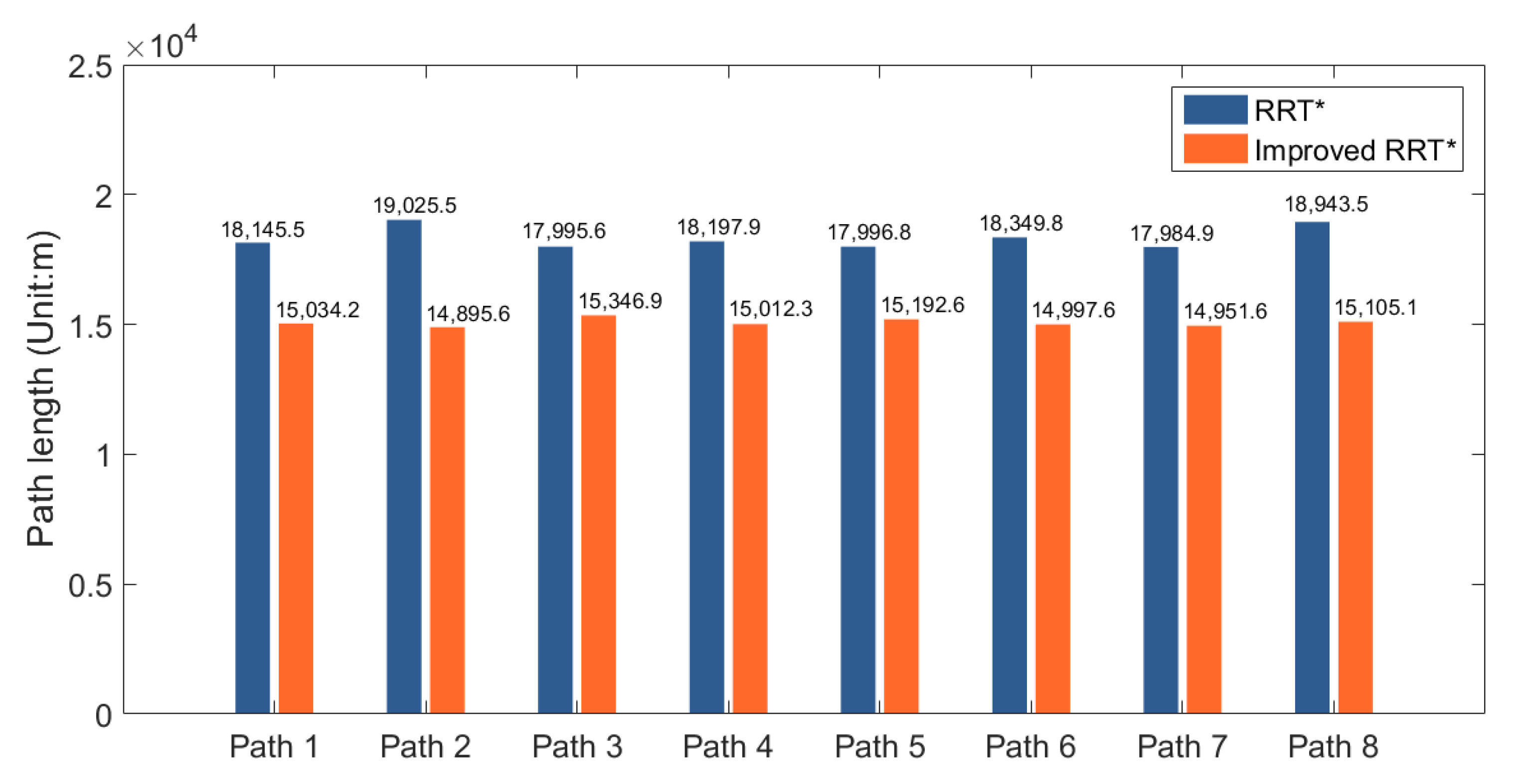
Figure 1, the improved RRT* algorithm is first used to generate the corresponding path database. In order to demonstrate the performance of the path planning results in the database, choose 10 paths to compare their length and time with the original RRT* algorithm. The statistical results are shown in the following
Figure 3 and
Figure 4:
Analyzing the data from
Figure 3 and
Figure 4, it can be concluded that the developed RRT* algorithm has notable improvements in both planning effectiveness and efficiency, with a shorter planned path and reduced planning time. This result indicates that the improved RRT* algorithm has certain advantages, which also guarantee the quality of data in the path database.
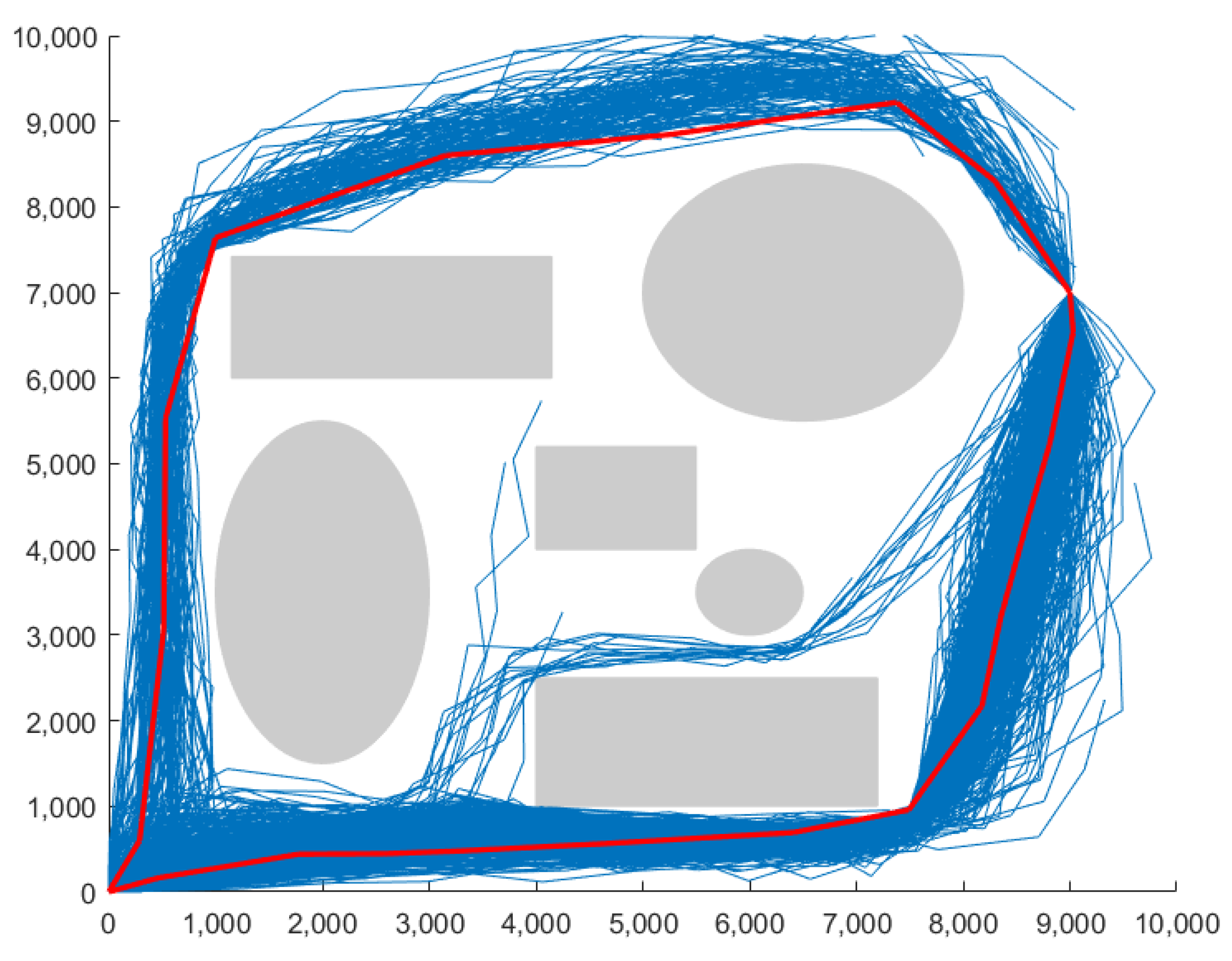
The DB-RRT* algorithm provides optimized route information points. Due to the full consideration of the constraint information of the vehicle and the cluster analysis through the DB-RRT* algorithm, the randomization and contingency of the single planning result can be avoided, and the results of the reliable route point are obtained. Furthermore, reliable data support is provided for the subsequent flight trace flight, which also averts the mismatch of data requirements caused by the separate design of path planning and aircraft tracking among other problems. The simulation outcome is shown in
Figure 5.
In
Figure 5, the blue lines represent the path information database generated by the improved RRT*, and the red line represents the path information obtained by the DB-RRT* algorithm. It is able to be reckoned that the improved RRT* algorithm may cause a few cases of planning failure. This phenomenon should be avoided in the application scenarios of UAV autonomous flight. After combining the analysis and filtering functions of DBSCAN, the failed waypoints will be excluded from the feasible solutions, which will greatly promote the success rate of planning and ensure the sub-optimality of the planning results.
What is more, through the assessment criterion, the safety performance and smoothness of the path are further compared and filtered. However, due to security and optimization considerations, although some paths can still reach the target safely, they still will not be screened out.
4.2. Simulation Results of Sliding Mode Guidance Law Based on Angle Constraints with Finite-Time Convergence
For the guidance law with angle constraint based on sliding mode control with finite time convergence designed in
Section 3, the corresponding simulation verification is carried out.
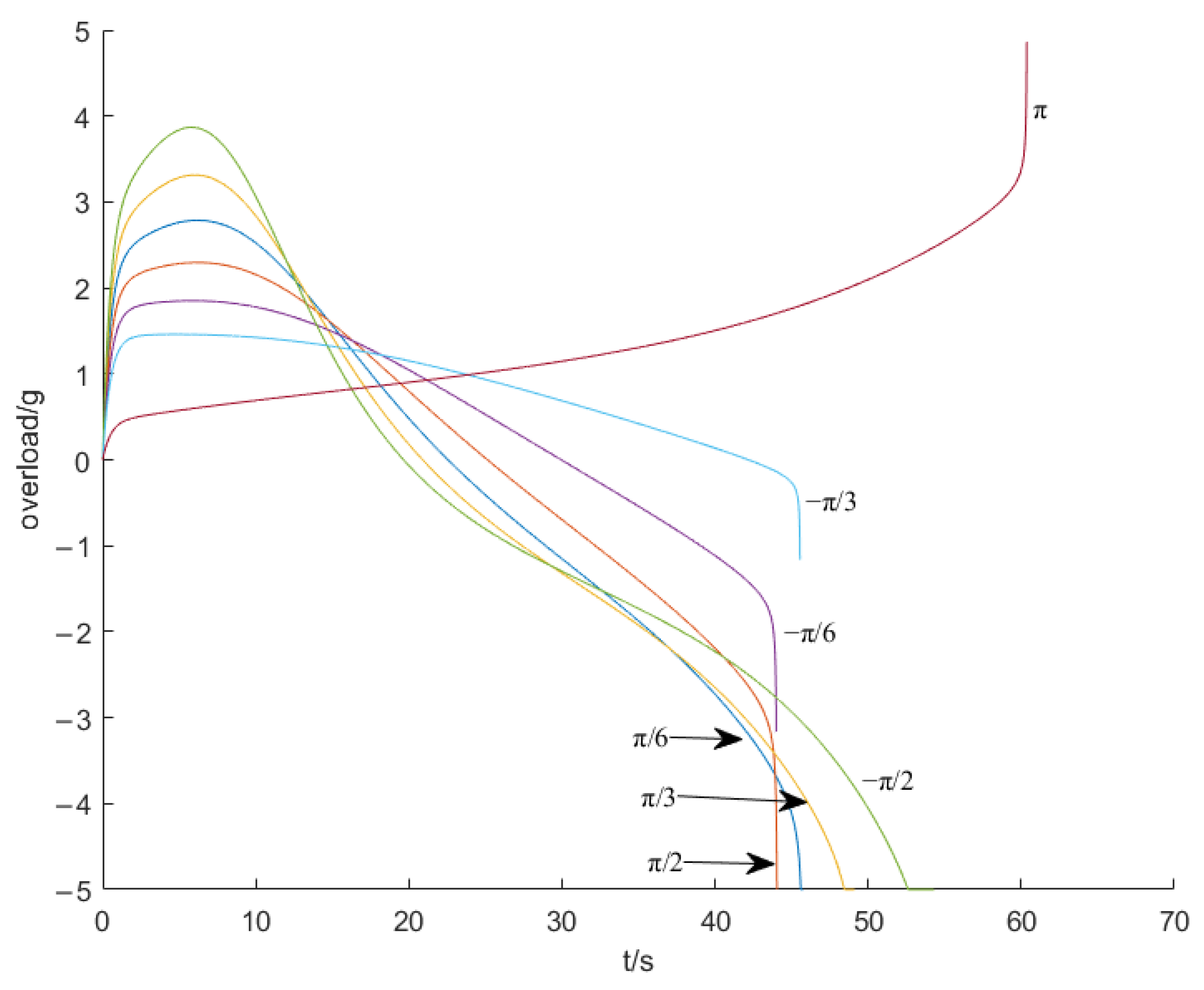
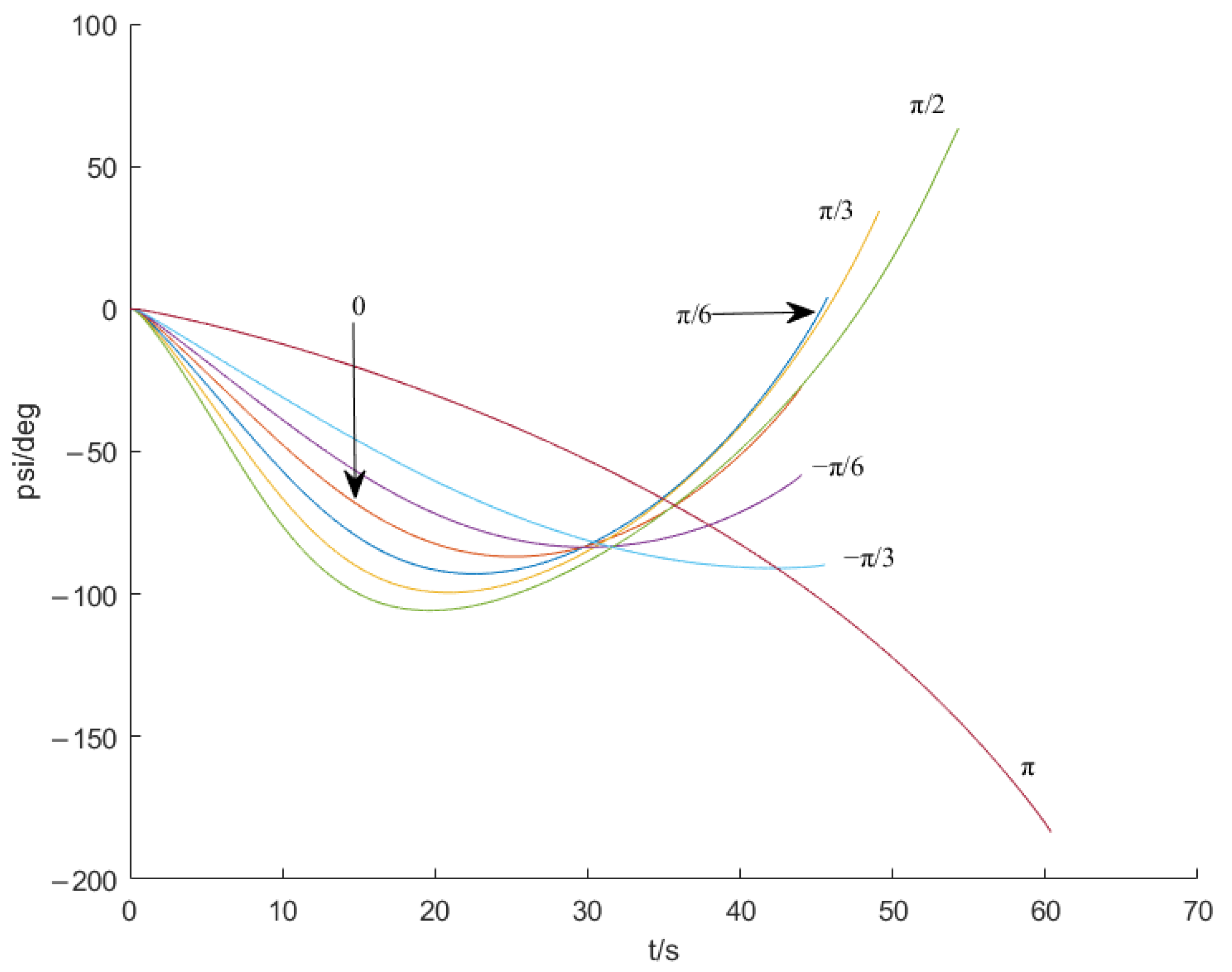
The simulation conditions are
. Take the starting point (0 m, 0 m) as the origin, and the target point is denoted as
. Thus,
. The designing parameters are given as
. And the angle constraints are required as:
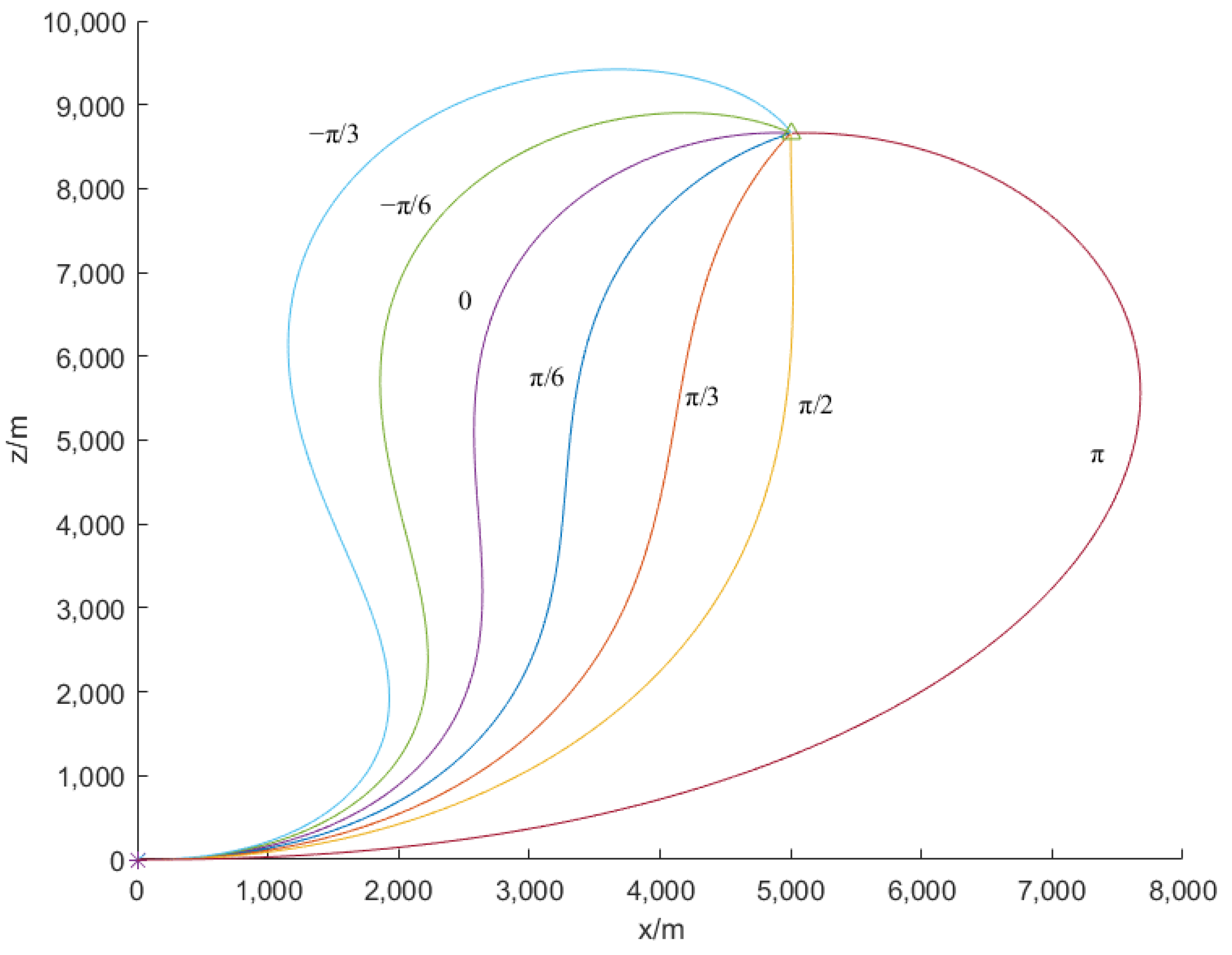
. The motion diagram, the overload result graph, and the trajectory inclination angle result graph are shown in
Figure 6,
Figure 7 and
Figure 8.
It can be concluded from the simulation results that the guidance law with angle constraint based on sliding mode control designed in this section can converge within the finite time, and the designed overload instruction is within the available overload range of the UAV. Given appropriate control parameters, the aircraft can reach the target point with arbitrary angle constraints. This can lay the foundation for autonomous flight guidance technology.
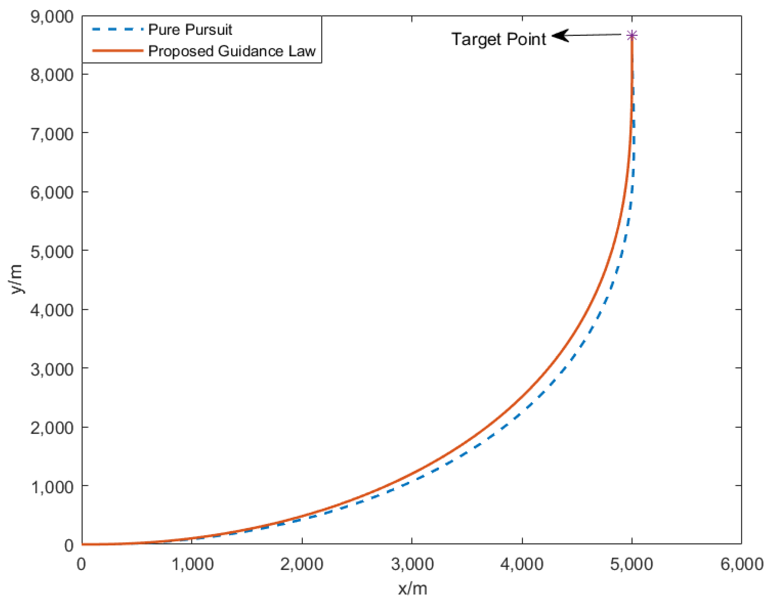
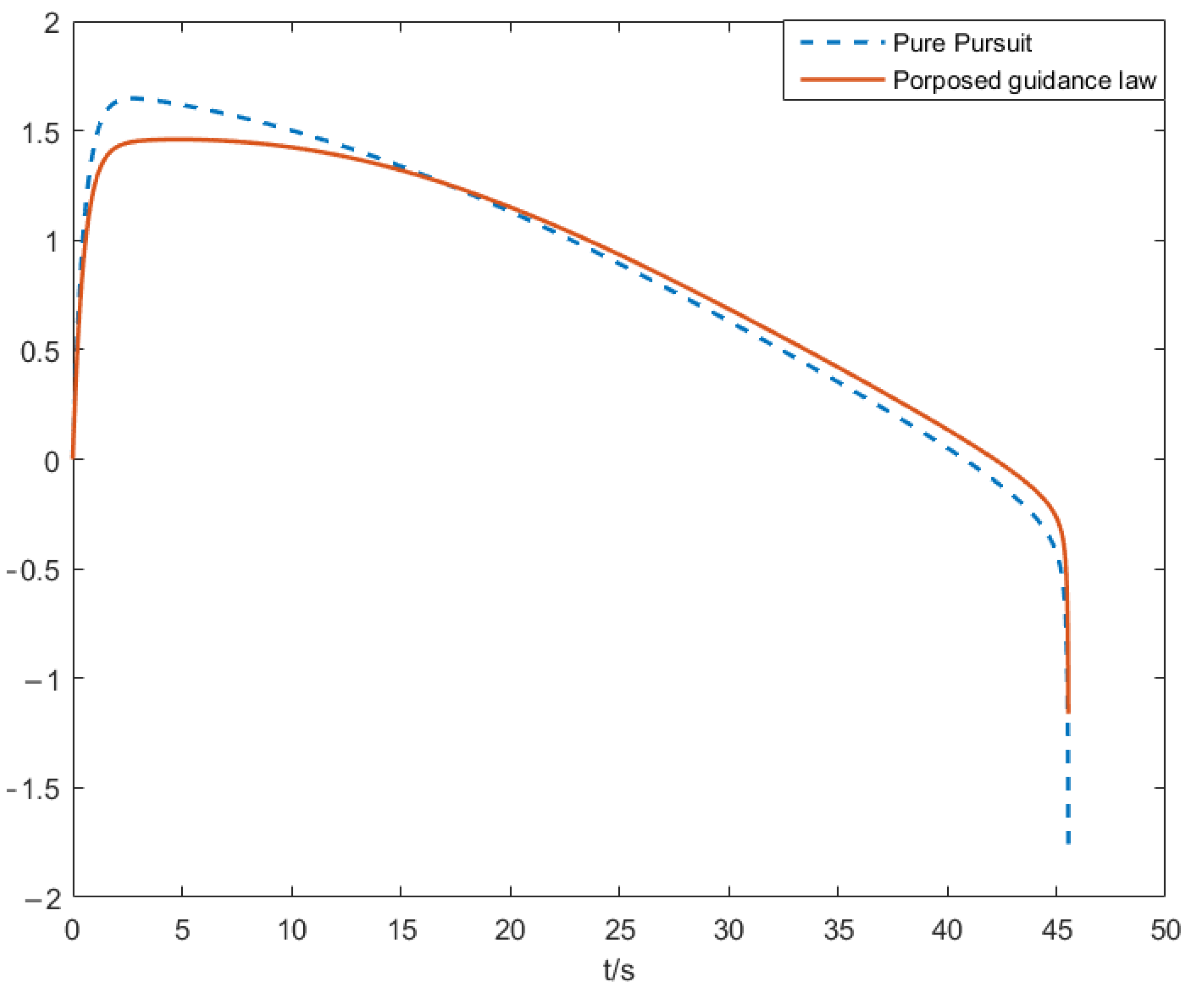
To further demonstrate the performance of our proposed guidance law, the pure pursuit method [
40] is compared with the proposed method. Given the starting point position, target position, and terminal angle constraint, these two methods are adopted to compare the results. The flight trajectory comparison diagram is shown in
Figure 9, and the command overload comparison diagram is in
Figure 10.
As seen from
Figure 9, compared with the trajectory of the two methods, the trajectory using the pure pursuit method is slightly longer compared with the trajectory of the proposed method, resulting in a slightly longer flight time when using the pure pursuit method. From
Figure 10, the maximum overload using the pure pursuit method is also larger than the maximum overload in our proposed method. Therefore, in such application scenarios, the proposed algorithm has slightly better performance in flight time, flight path length, and overload.
4.3. Simulation Results of Autonomous Flight Guidance Technology
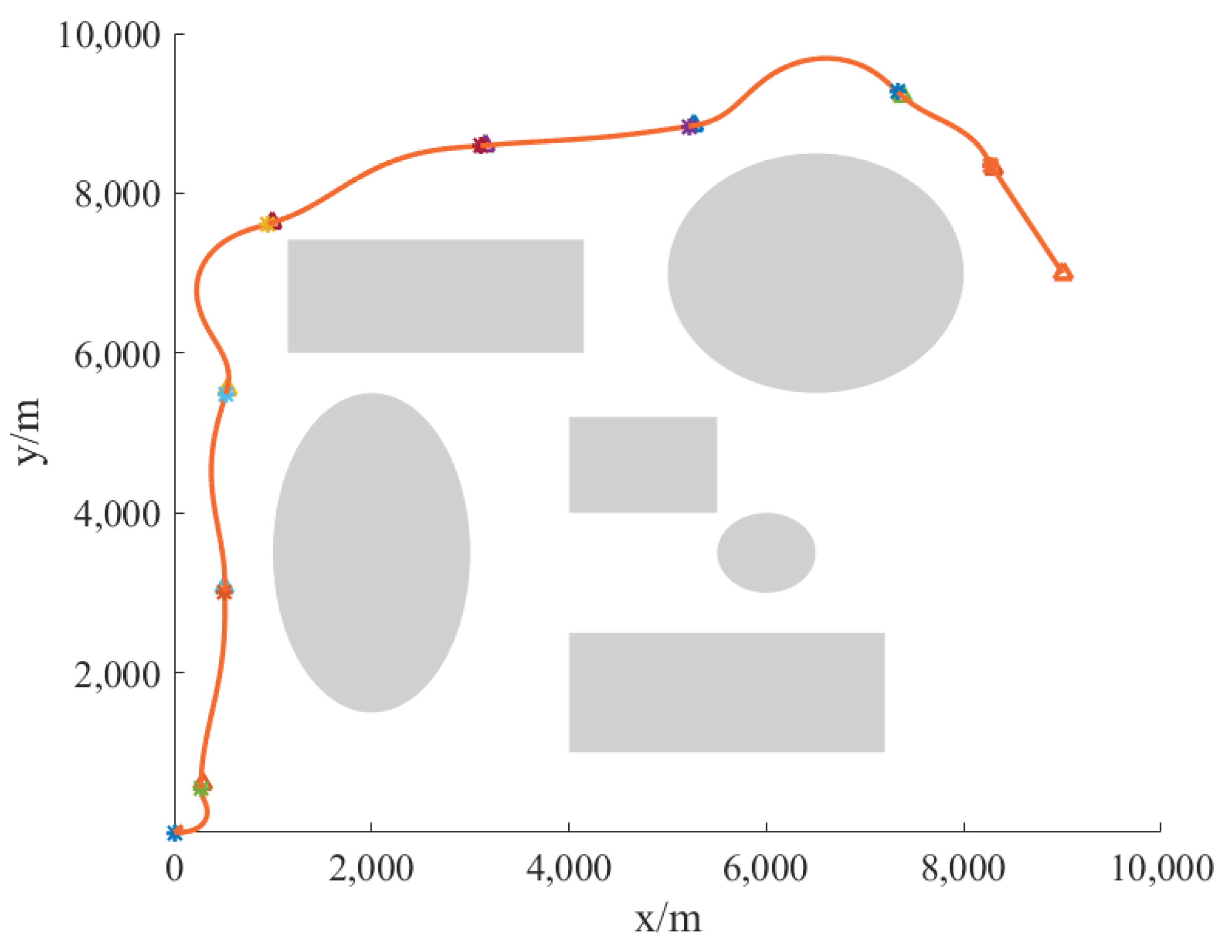
Based on the above statements, the entire process of autonomous flight technology of aircraft can be shown as
Figure 11.
The whole process can be described as follows: the mission planning system gives the initial point information, target point information, and environmental obstacle information. According to the instructions, the proposed DB-RRT* algorithm generates a series of waypoints to make sure there is an optimized, reliable, and safe path. The above process is designed offline. Knowing the generated waypoint information, the aircraft can track the waypoint information online based on the sliding mode guidance algorithm, and finally obtain the actual flight trajectory result.
For verifying the strategy of “offline design + online flight”, simulation verification is carried out. Set the initial starting point as (0 m, 0 m), and
. The parameters are denoted as
. For other specific parameters, please refer to the simulation parameters in
Section 4.1 and
Section 4.2. The radar threat, fire threat, obstacle, and no-fly area in the environment are reasonably simplified and equivalent to different graphics. Combined with the content designed in
Section 2 and
Section 3, simulation verification under different scenarios is carried out. The simulation results are shown in
Figure 12 and
Figure 13.
As the simulation outcomes display, the improved DB-RRT* method can successfully obtain safe and feasible flight paths for UAVs in different environments. From the simulation results, it can be drawn that the planned path is sub-optimal, and the process of path planning and iteration also ends quickly. Combining the finite-time convergence guidance law with angle constraints and adopting the framework structure of “off-line planning + online flight”, the UAV can be controlled to complete the flight path autonomously according to the waypoint information within a limited time.
Additionally, in different scenarios, the aircraft can generate a safe and sub-optimal path to reach the target point, proving the effectiveness of the proposed strategy.
5. Conclusions
To further enhance the autonomous flight and planning capability of UAVs, this paper presents a framework and scheme to integrate path planning and trajectory tracking technology. Firstly, the RRT* algorithm is improved. The promoted algorithm is about 20% shorter than the original path length, with a 50% reduction in planning time. Furthermore, an improved DB-RRT* algorithm is proposed to optimize and extract the waypoints. The assessment criterion is established to evaluate the flight reliability and optimization degree of the generated trajectories, overcome the contingency and randomness of single planning of RRT* algorithm, and obtain the planned waypoint information that meets the constraints of aircraft dynamics, ensuring the safety and reliability of the UAV. Secondly, the guidance problem of the aircraft is transformed into the trajectory tracking problem. On this basis, the angle-constrained guidance law with finite time convergence is devised, and its stability as well as the characteristics of finite time convergence are proved. The “offline design + online flight” scheme can navigate the aircraft based on the waypoint information and complete the trajectory tracking. Lastly, the key technologies are validated through a series of simulations. Furthermore, under the integrated framework, the aircraft can autonomously navigate to the destination and avoid obstacles, and the real-time step size of the simulation meets the data transmission requirements during the actual flight, offering the advantage of online real-time planning. Above all, the feasibility of the utilized method is proven to offer a solution and provides technical support for the realization of the autonomy and intelligence of UAVs.

