Article

UAV Digital Twin Based Wireless Channel Modeling for 6G Green IoT

1
China Telecom Research Institute, Beijing 102209, China
2
School of Electronics and Information Engineering, Beihang University, Beijing 100083, China
3
State Key Laboratory of Networking and Switching Technology, Beijing University of Posts and Telecommunications, Beijing 100088, China
*
Author to whom correspondence should be addressed.
Drones 2023, 7(9), 562; https://doi.org/10.3390/drones7090562
Submission received: 1 August 2023 / Revised: 18 August 2023 / Accepted: 28 August 2023 / Published: 1 September 2023
(This article belongs to the Special Issue Advances of Drones in Green Internet-of-Things)

Abstract

:
This paper explores the advancements of drones in the context of sixth-generation mobile communication technology (6G) green Internet of Things (IoT) through the utilization of digital twin (DT) technology within unmanned aerial vehicle (UAV) networks. We propose a framework for DT-based UAV applications in the realm of green IoT, where distinct tasks within the digital twin interact with physical-world UAVs through task manager scheduling. We characterize the radio frequency (RF) attributes of the DT using three-dimensional (3D) millimeter-wave (mmWave) radar imaging on UAVs. The wireless channel modeling, based on ray tracing, underscores the alignment of RF domains between the DT and the physical UAV in a bid to take advantage of multipath reflections and save communication energy. Our numerical findings have justified the efficacy of the drone-enabled DT platform in achieving accurate RF representation of UAVs for the intelligent operation and management of IoT-based green UAV networks.

1. Introduction

In order to meet the demand for broadband access at any time and in any region, not only for people but also for a wide variety of things, the 6G will build a space-air-ground integrated network (SAGIN) [1,2]. The deployment of UAVs as part of the aerial network component of the SAGIN can help address the challenges of constructing 6G networks. Since 6G networks will operate at higher frequencies, there are tradeoffs in coverage area, path loss, and infrastructure costs [3,4]. However, UAVs provide new capabilities as aerial communication nodes to complement the overall 6G network architecture. Their mobility and positioning flexibility make them well-suited for on-demand coverage and relaying in hard-to-reach areas.
UAV-assisted communications can provide wide-area IoT access to temporary hotspots and areas without terrestrial network coverage. For example, it can provide services, such as ensuring emergency communications, crop monitoring, and monitoring rare animal-inhabited areas. Moreover, by integrating communication and radar integration functions on UAVs, centimeter-level high-precision positioning and high-precision ground imaging can also be achieved. It further realizes services, such as high-precision navigation, precision agriculture, emergency rescue, and intelligent traffic scheduling. In this way, the goal of 6G communication and perception integration can be well realized, further helping to realize the true meaning of the everything intelligent connection. The integrated hardware equipment and intelligent application software can greatly reduce the energy consumption of IoTs and achieve sustainable green IoTs.
Moreover, the bandwidth, frequency overlap, and exponential increase in devices driven by 6G requirements can be mitigated through advances in UAV technology for green IoTs applications. UAVs can incorporate mmWave radios to take advantage of the abundant bandwidth at high frequencies. With wider channels above 400 MHz [5], the throughput for UAV-based green IoT services can be significantly improved. In addition, the integration of communication and radar on UAVs can also reduce the volume, energy consumption, and cost of communication equipment and radar equipment and realize the green IoTs based on UAVs. Intelligent UAV deployment and coordination will help unlock the full potential of 6G for a wide range of transformative applications.
The efficiency of a system and the intelligence of UAVs in flight can be significantly enhanced through the application of traffic simulation and virtual testing. This is especially important in the context of IoT, where optimal resource utilization and energy efficiency are paramount. Advanced virtual simulation technologies such as DT facilitate the formulation of optimal routes for autonomous aerial vehicles and vehicular traffic, contributing to reduced energy consumption and carbon footprint, which are key goals of green IoT.
DT, due to its ability to model the entire life cycle of an operating system and synchronize with real entities, has emerged as a groundbreaking technology. The methodologies developed through DT are anticipated to find extensive applications in modern communication infrastructure, particularly in green IoT systems where real-time monitoring and management of devices can lead to significant energy savings [6].
Realizing a network digital twin requires several potentials, including network perception, network modeling, and intelligent data processing. These advanced methodologies, central to green IoT, enable the construction of a digital twin of a physical network, which serves critical functions, such as physical network querying, virtual network evaluation, and virtual-real network interaction. This can contribute to energy-efficient network operation, a core principle of green IoT.
Despite the complexity and intricacies of intelligent UAV swarm collaboration, which considerably limit its widespread application, the utilization of DT in intelligent UAV networks is recommended. This technology can play a significant role in green IoT by enabling more efficient flight paths, reducing energy consumption, and thus enhancing the environmental sustainability of these systems.
The integration of digital twins for UAVs with cloud servers facilitates advanced route planning for UAV operators, effectively diminishing the resources and duration dedicated to path formulation. In the context of edge networks, the swift synchronization between digital twins and the mobile edge computing (MEC) platform minimizes the necessity for recurrent data exchanges. This not only amplifies energy conservation and traffic fluency for UAV users but also resonates with the ethos of green IoT [7,8,9].
The requirement for multiple UAVs to communicate concurrently further complicates the already intricate wireless channel characteristics. The DT platform can provide an accurate virtual representation of UAVs’ wireless channels, thus enabling the platform to carry out reliable and energy-efficient channel modeling by employing artificial intelligence (AI) technology, an essential feature for green IoT systems. This study investigates the potential of DT technology for modeling wireless channels for UAVs using radar imaging and ray-tracing techniques, with a focus on their implications for energy efficiency in green IoT systems. Specifically, this research considers the reflection properties of incident waves by moving UAVs and the reflection effects of radio waves between multiple UAVs, both of which have significant implications for the energy efficiency and environmental sustainability of IoT systems [10].
The rest of this paper is structured as follows. Section 2 introduces the fundamentals of digital twin-enabled UAV networks, with a specific focus on their applications in green IoT systems. Section 3 delves into the exploration of UAV radar imaging in the mmWave Band and Section 4 takes this a step further by developing ray-tracing-based aerial mmWave channel modeling, a crucial aspect for energy-efficient communication in green IoT. Then, Section 5 provides the simulation results to validate our proposed method, followed by Section 6 to conclude this paper by summarizing the potential impacts of our findings.

2. Digital Twin-Based UAV Communications for Green IoT

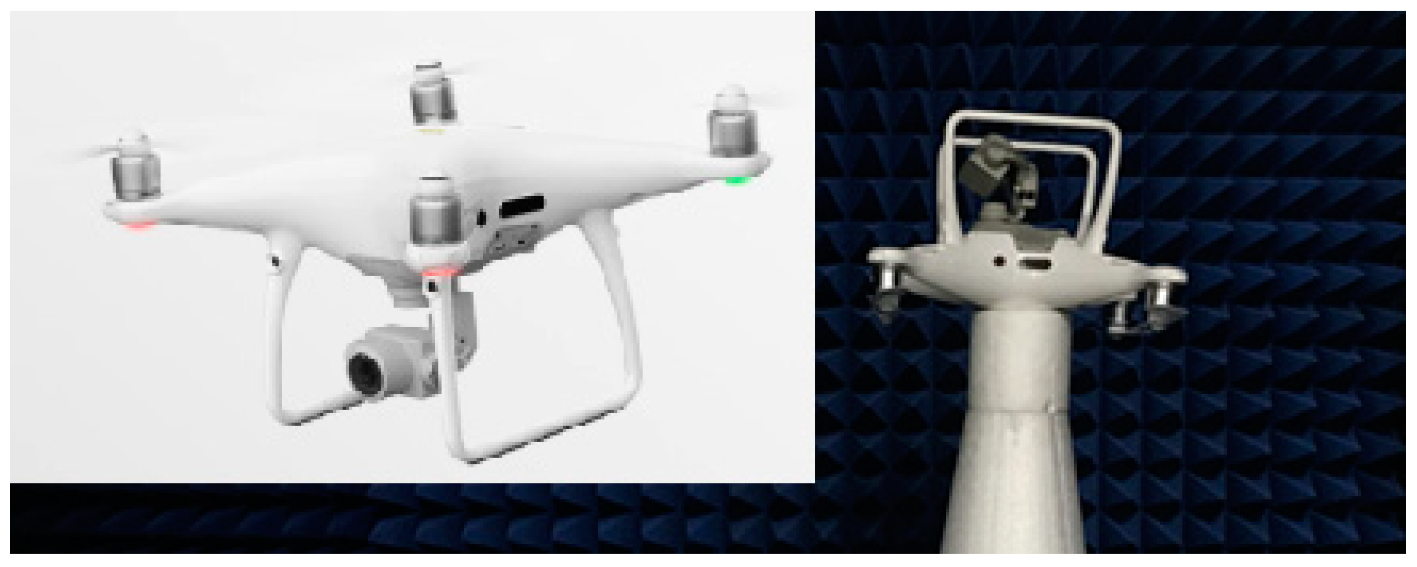
For the purpose of this study, we chose a professional UAV model, the DJI Phantom 4 Pro quadcopter, produced by SZ DJI Technology Co., Ltd. (Shenzhen, China). This UAVs is a technologically advanced aerial imaging solution. Its 1-inch CMOS sensor allows 20 MP and 4 K/60 fps video capture, while the OcuSync 2.0 system guarantees reliable connectivity. Enhanced with five-direction obstacle sensing for safety and a specialized remote controller for precision, this drone’s intelligent features streamline its operation, making it a preferred choice for professional creators. Figure 1 provides a schematic representation of the measurement setup, which includes a UAVs being tested and a radar front-end that is supported by a tripod and connected via microwave wires [11,12].
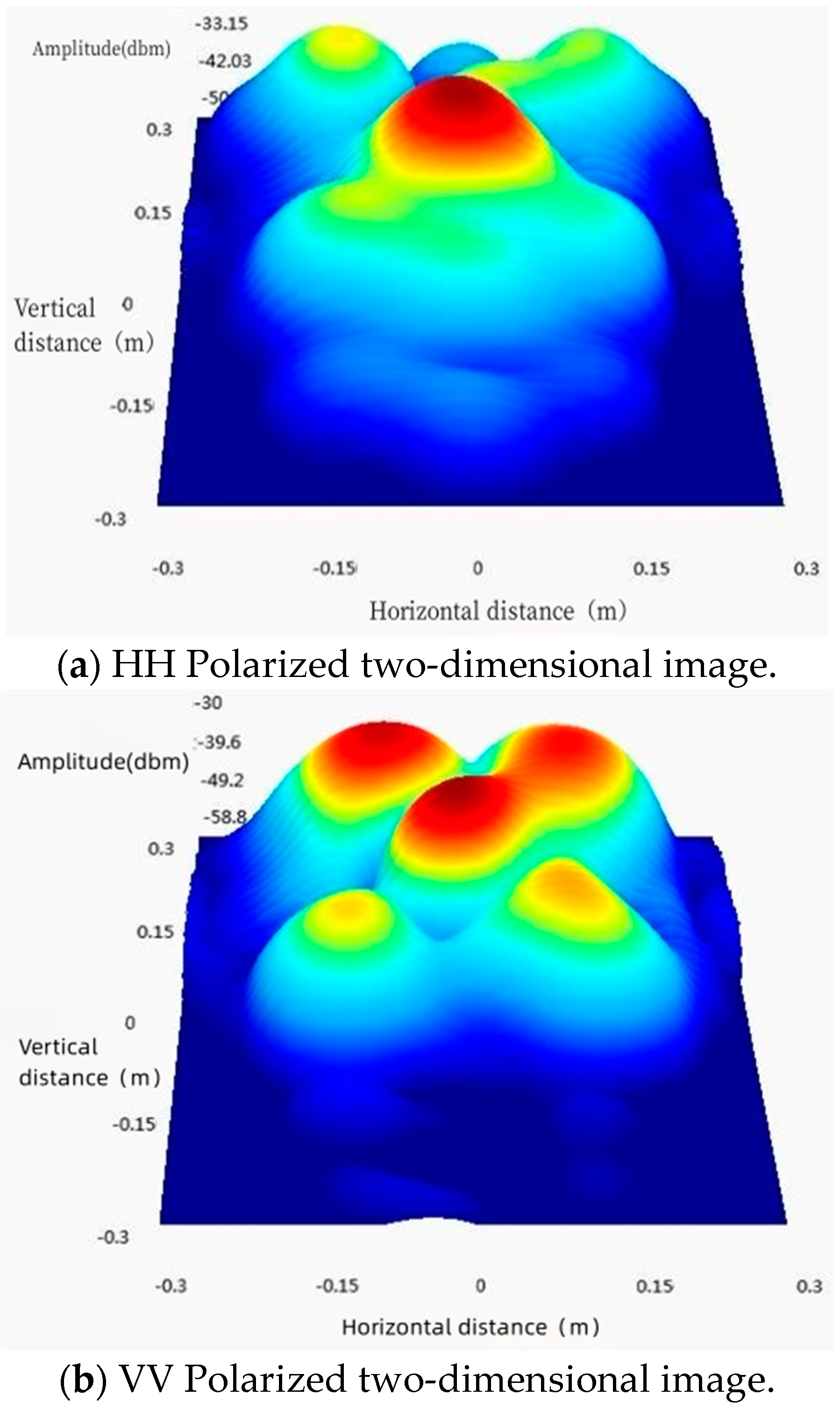
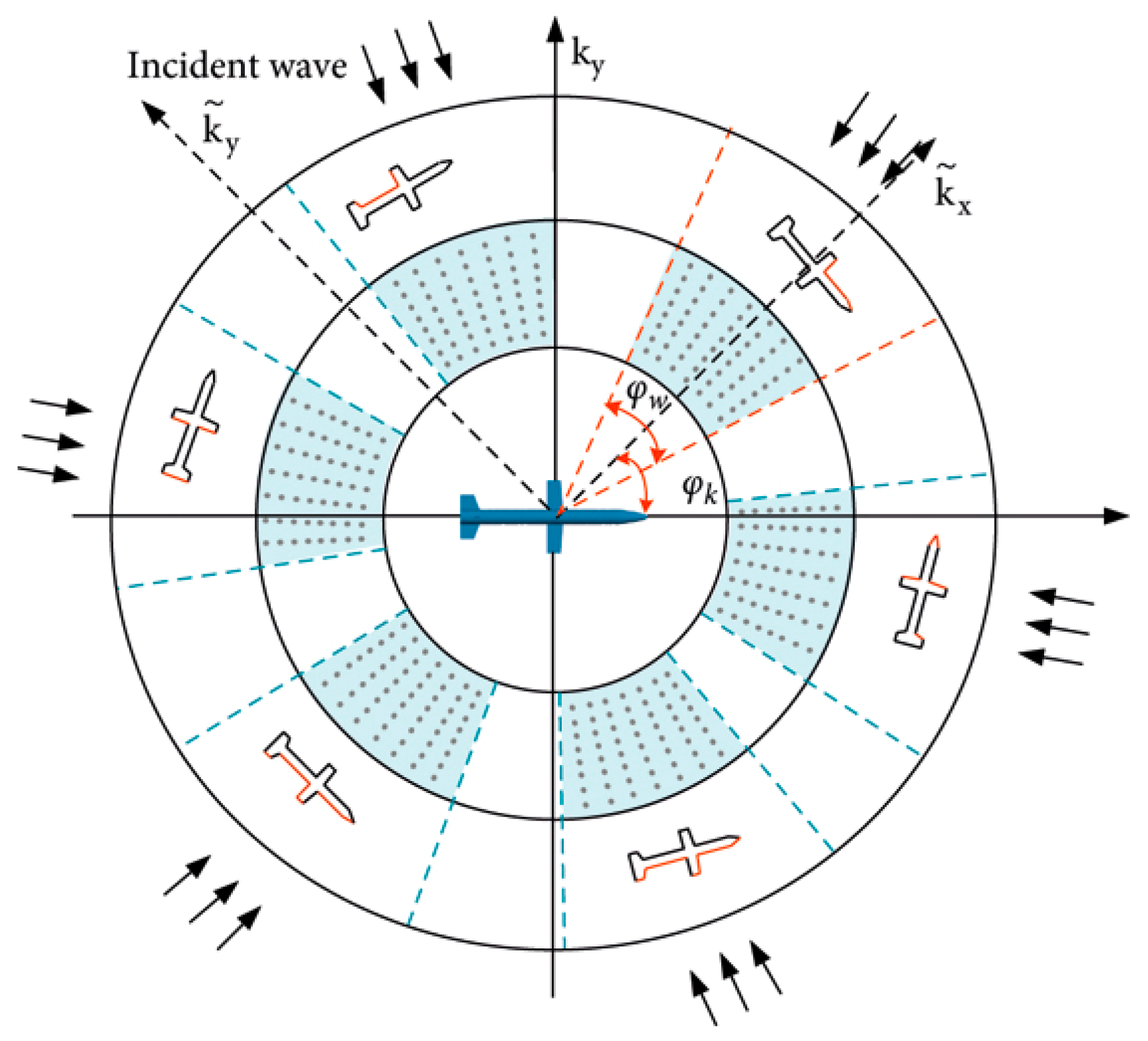
The significance of UAV specification in radar imaging lies in augmenting the perception and recognition capabilities of UAVs, which, in turn, fosters enhanced flight safety and mission execution efficiency [13]. Radar imaging, as an active sensing technology, employs the transmission of radar signals and the reception of reflected signals to ascertain information pertaining to the distance, direction, and speed of a target.
The DT concept is a burgeoning proposition that has attracted notable attention in recent years, particularly within the context of IoT [8]. DT’s ability to faithfully replicate physical systems on digital platforms offers substantial potential for augmenting the energy efficiency and sustainability of IoT systems [14].
Currently, the most salient applications of DT are manifested in engineering and construction, with intense research and focus being channeled towards its utilization in intelligent manufacturing, including the fabrication of energy-efficient IoT devices [15]. DT encompasses a diverse range of data types, such as physical models, sensor updates, and operational histories. It synthesizes multi-disciplinary, multi-physical, multi-scale, and multi-probability simulation processes, thereby achieving a virtual mapping. This facilitates the monitoring and optimization of the entire lifecycle of corresponding physical equipment, aligning with the principles of green IoT and resulting in significant energy savings [16].
DT transcends mere conceptualization and may be considered a comprehensive digital mapping system for one or more essential and interdependent equipment systems, inclusive of those engaged in green IoT [17]. As a universally applicable theoretical and technical system, DT has vast potential applications across various domains. Its relevance to green IoT is pronounced, enabling the creation of more energy-efficient products in design and manufacturing, reducing energy consumption in medical analyses, and fostering the development of sustainable structures in engineering construction.
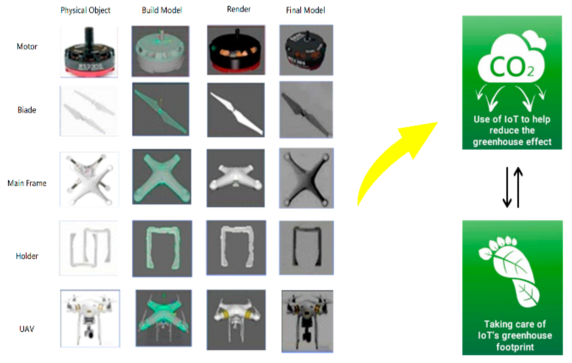
As depicted in Figure 2, a UAVs physically integrates several components, such as NVIDIA’s physics engine, moments, rigid bodies, and joints. This not only allows for a realistic simulation of the UAVs’ six degrees of freedom but also enables the optimization of the UAVs’ energy consumption, making it a key tool for green IoT. The force and moment components, extensively utilized in propellers and motors, can be optimized for energy efficiency. The joint components aid in connecting the internal parts of the UAVs, and their efficient design can contribute to the overall energy efficiency of the UAVs, an important consideration in green IoT [18].
The physics of multi-rotor UAVs encompasses both internal forces and external forces resulting from contact with other objects. These dynamics play a vital role in the context of IoT, where efficient energy use and sustainable operations are paramount. The physical motion of a multi-rotor UAVs is primarily governed by the differential in propeller speeds. A significant consequence of the disparate speeds of the propellers is a shift in the UAV’s total thrust across all directions [19]. This, in turn, allows for precise adjustments to the UAV’s acceleration and attitude angles in all directions, leading to an optimized state of mobility. This optimization can contribute to energy savings, which is a key objective in green IoT.
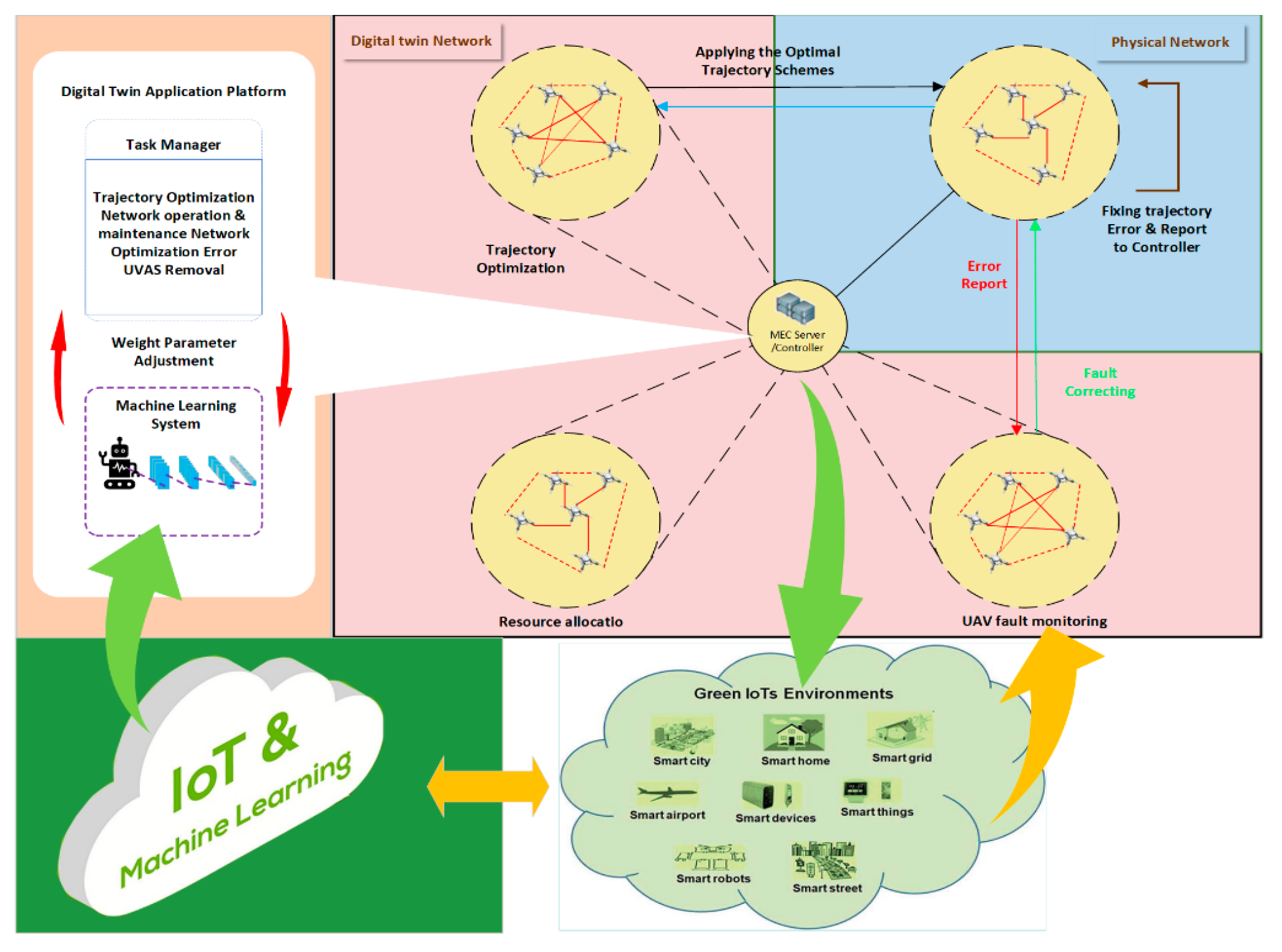
In intelligent UAV networking based on DT, the closed-loop interaction between the digital and physical domains enables UAVs to swiftly adapt to complex and dynamic environments. This facilitates the autonomous execution of advanced functions, such as trajectory optimization and resource allocation, both crucial for energy efficiency in green IoT systems [20]. In order to ensure precise DT modeling and meet the data volume requirements for simulation verification, base stations necessitate extensive bandwidths and high transmission rates, which can lead to efficient and sustainable data service responses.
Data of varying values can be distributed across core clouds, edge computing devices, and terminal devices, optimizing resource use and energy consumption. AI technology can then perform data value mining, enabling dynamic scenario adaptation and intelligent policy optimization, key features in the pursuit of green IoT.
The DT of the UAV network, being its digital mirror, replicates the same environment, UAVs, topologies, and various data as the actual UAV network. It serves as a sophisticated “replica” of the actual network [10], providing a platform for energy-efficient operation, a critical aspect of green IoT. The DT application platform can provide a digital verification environment that closely resembles the actual UAV network, allowing for the optimization of energy-efficient UAV path planning, driving strategy, and network operation and maintenance.
The reliability of AI models and pre-validation results trained on the DT application platform surpasses that of traditional simulation platforms. Consequently, as depicted in Figure 2, the AI intelligent decisions, which are trained on the DT application platform, can be directly dispatched to the actual UAVs via the MEC server. This integration allows UAVs to make real-time, informed, and energy-efficient decisions without human intervention, an important consideration in green IoT.
The amalgamation of DT and MEC servers within UAV networks can culminate in augmented performance, heightened safety, and decreased expenditures. These outcomes are congruous with the guiding principles of IoT. Therefore, the utilization of DT and MEC servers represents a pivotal approach to furthering the objectives of green IoT, particularly in relation to the promotion of efficient and sustainable operations.

3. UAV Radar Imaging in mmWave Band

3.1. mmWave Communications for Green IoT and UAV Connectivity

The mmWave spectrum experiences significant propagation loss, consequently constraining its coverage area. However, in the context of IoT, this could be viewed as an advantage, as it encourages the implementation of smaller, more energy-efficient networks. Characterizing the RF characteristics of the DT using 3D millimeter-wave radar imaging is a complex process involving key steps, such as signal generation, object scanning, data analysis, and DT creation. By precisely capturing the RF attributes of the physical UAVs and replicating these attributes in the virtual model, a close alignment between the DT and the physical entities is ensured.

3.1.1. The Application of mmWave-Based UAV Communications in Green IoT

Given that direct transmission is the primary propagation mode during mmWave transmission, it is deemed more fitting to utilize mmWave as the communication medium between the air and ground. This direct method of transmission can reduce energy consumption, aligning with the principles of green IoT. At present, mmWave is one of the main communication frequency bands used in low-orbit satellite communications. It is reasonable to posit that mmWave is more appropriate for UAV communications at lower altitudes than low earth orbit (LEO) satellites, which can further be improved to a certain extent under the condition that the communication range, data rate, coverage, delay, cost, and other factors, satisfied [21,22].
In mmWave-based UAV communication systems, the transmission requirements of large traffic volumes can be met, an essential aspect of green IoT. MmWave is also more suitable for high-capacity hotspot area coverage and wireless backhaul as a substitute for optical fiber in terrestrial communication systems, contributing to the energy efficiency goals of green IoT. Industrial cameras mounted on UAVs capture large volumes of data in the form of infrared images and high-definition videos. Such application scenarios necessitate transmission rates in the order of hundreds of megabits or even gigabits [5]. Another application where UAV mmWave communication proves beneficial is film and television production, where it can support the capture and transmission of ultra-high-definition video [23,24].
Moreover, due to the low latency characteristics of mmWave, near-zero delay in UAV communication can be achieved, thereby significantly enhancing the safety performance of UAVs, and reducing energy waste. Equipping UAVs with mmWave radar can enable obstacle avoidance and ground-like flight, thus making them invaluable in application fields, such as agriculture, forestry, plant protection, and line inspection, all of which can benefit from green IoT principles, as shown in Figure 3.
UAV mmWave communications can foster the integration of future 6G communication and sensing, one of the fundamental features of 6G networks. The research direction of integrated communication and sensing technology based on the wireless spectrum (particularly high-frequency band) was proposed in 2018. The integration of communication and sensing can reduce the size and energy consumption of communication and radar devices, improve spectrum usage efficiency, and provide superior services for vertical industries such as UAVs and telematics applications, all crucial aspects of green IoT.

3.1.2. Green IoT-Enabled Aerial mmWave Channel Characteristics

The principal propagation mode of mmWave is the direct wave, characterized by higher transmission loss and a weaker ability to circumnavigate obstacles. These characteristics make its shadow fading substantially distinct from those of low-frequency waves. In the context of terrestrial communication, mmWaves are prone to obstruction by various objects, such as buildings and human bodies. However, in aerial mmWave wireless channels, such as those between UAVs and ground-based stations, there’s less obstruction. This factor makes mmWave ideal for Green IoT, as it can lead to improved transmission performance compared to ground-based communications, contributing to energy efficiency.
The aerial mmWave channel has several key characteristics in the context of Green IoT:
  • A substantial frequency span: mmWave boasts abundant available resources, and both the system bandwidth and channel bandwidths can be large. As the frequency increases, the decay of electromagnetic wave energy accelerates with distance, and weather factors such as rain and fog become more influential [25,26,27]. This large frequency span, combined with the direct propagation mode of mmWave, allows for energy-efficient communication in the Green IoT context.
  • Deficient mobility support: mmWave is suited for fixed scenarios with relatively high traffic demand. However, in the context of Green IoT, stationary devices or those with low mobility can benefit from energy savings due to the reduced need for frequent handovers or network reconfigurations.
  • Influence of technology diversity on channel transmission: To counteract the spatial propagation loss of mmWave, beamforming technology is typically employed to boost antenna gain. In the future 6G landscape, more diverse technologies, such as super massive multiple input multiple output (MIMO)/holographic MIMO, intelligent reconfigurable surfaces (IRS), and communication-aware integration (CAI), may be utilized. These technologies can help reduce energy consumption by improving the efficiency of data transmission, aligning with the principles of Green IoT.
Given the complexity of mmWave channels and the need for more research in this area, Green IoT can benefit from the development of energy-efficient algorithms and technologies for mmWave communication. Accurate channel modeling, for instance, can lead to more efficient usage of the spectrum, contributing to energy savings. Similarly, developing technical parameters and performance indicators for different technologies can help optimize energy use in various Green IoT applications.

3.2. UAV Radar Imaging by ISAR

As radar emerges as the preferred method for detecting UAVs, the necessity for an accurate assessment of UAV radar signatures is becoming increasingly paramount [28,29,30,31]. Inverse synthetic aperture radar (ISAR), an image processing technique, leverages target motion rather than radar motion to achieve this [32]. This technique offers a more accurate depiction of scenarios where the measurement geometry is determined by the collected data and is not known beforehand.
The fundamental concept behind ISAR is to utilize the geographic variety of data collected to concentrate a high-resolution picture. A measurement session produces a complex number matrix by using the apparatus mentioned above and moving the radar head incrementally along z. We can get E i , k , m = I i , k , m + j Q i , k , m , where I i , k , m and Q i , k , m are the in-phase and quadrature components, respectively.
The fundamental concept of the windowing method we used is shown in Figure 4. To preserve the best resolution possible, the spinning circle is split into four partly overlapping 180° arcs.
The fundamental formula for (x, y, z)-coordinated general point focusing is [28]:
I ( x , y , z ) = i , k , m E i , k e j 4 π c f i R k , m ( x , y , z )
where R k , m ( x , y , z ) is the separation between the place denoted by the indices k and m and the image point (x, y, z). At each arc, a window that is projected to the chord subtended by the same arc is applied prior to focusing. The chords are parallel to the x and y axes if the arcs are arranged as in Figure 4. Each arc is independently treated to the ISAR algorithm, and by releasing the phase, the resulting image I w ( x , y , z ) is added incoherently.
  I w ( x , y , z ) = n = 1 4 | I n ( x , y , z ) |
As an illustrative example, Figure 5 presents our measurement of the DJI Phantom 4 Pro UAVs employing the Windowing process at the 10 GHz ray frequency. Figure 5a exhibits a two-dimensional image under HH (Horizontal transmission and Horizontal reception) polarization. In this polarization scheme, the signal is both transmitted and received in a horizontal manner. The image captures the reflection of the signal from the UAVs, evidenced by a bright spot at the center of the image. The surrounding area appears relatively dark, indicating a low reflection level. Upon closer examination, the bright spot representing the UAV reflection has a roughly circular shape and is positioned near the center of the image. The darkness of the background suggests negligible radar returns from the surrounding environment. This is expected for HH polarization, which tends to interact weakly with vertical structures. The high brightness of the UAV highlight demonstrates that the HH scheme produces excellent reflection from the horizontal components of the UAV body.
Figure 5b represents the same UAVs under the VV (Vertical transmission and Vertical reception) polarization scheme. This scheme involves the vertical transmission and reception of the signal. The resultant image captures a comparable reflection from the UAVs, albeit with a slight variation in shape and position compared to Figure 5a. Specifically, the UAV reflection has taken on a more elongated, oval-like shape and shifted slightly down and to the right. This discrepancy in the VV radar return arises due to the differential interaction of the signal with the UAVs, contingent upon its polarization. The VV mode exhibits greater sensitivity to vertical structures, resulting in enhanced returns from the vertical edges and body of the UAV. Furthermore, the viewing angle and orientation of the UAV may have changed between measurements, leading to the observed shape and position differences. Overall, Figure 5a,b demonstrates that HH and VV polarization schemes yield detectable yet distinct radar reflections from the UAV targets at 10 GHz frequency. This example highlights the ability to image UAVs using radar and the dependence of the measured returns on transmit/receive polarizations.

4. 3D Ray-Tracing Based Aerial mmWave Channel Modeling

In previous studies, it was commonly assumed that scatterers are distributed in a two-dimensional plane when analyzing the channel. This assumption disregards the impact of the elevation plane on channel analysis and is valid in the low-frequency range. However, as the frequency range widens, the signal’s propagation properties change, rendering the original assumption inaccurate in calculating channel parameters [27]. Therefore, it is necessary to adopt a three-dimensional propagation model to accurately transmit mmWave signals and obtain their propagation characteristics in the space, time, and frequency domains. Furthermore, this model can be extended to various transmission scenarios, including those involving green IoT technologies. The proposed wireless channel modeling based on ray tracing plays a crucial role in this process. Ray tracing simulates the interaction of RF signals with the environment, considering real-world conditions such as obstacles, reflections, diffractions, and scatterings. This not only ensures the precise alignment of the DT’s RF characteristics with the physical UAVs but also enhances the prediction and control of the UAVs’ behavior in real-world scenarios, thereby improving the overall efficiency and accuracy.

4.1. The 3D Ray-Tracing Method in Green IoT Channel Analysis

In the context of analyzing electromagnetic waves in the real physical external environment, the three-position ray tracing method employs electromagnetic waves as the object and light propagation as the fundamental principle to derive the characteristic parameters of radio wave propagation. This method allows for efficient 3D ray tracing to calculate the main component reflection, scattering, diffraction, and other related parameters. The 3D ray tracing method has demonstrated high reliability in accurately simulating mmWave channel characteristics and finds application in diverse measurement scenarios [28]. When employing the 3D ray tracing method to analyze electromagnetic waves in the context of green IoT, the first step involves geometric modeling of the scene, considering environmentally friendly elements and energy-efficient devices. The accuracy of the geometric modeling directly affects the correctness of the final results, ensuring the effectiveness of green IoT implementations. For instance, to incorporate UAVs into the model, one approach is to introduce the Doppler frequency shift, the micro-Doppler effect of the UAV itself and the 3D mmWave image of the UAVs into the simulation system, thus enhancing the accuracy of the simulation results, while considering the energy consumption and environmental impact.
The next step entails setting the simulation parameters within the simulation system, with key parameters including transmit power, angle of departure (AoD), antenna height, number of UAVs, etc., taking into account energy-efficient configurations and green IoT principles. Subsequently, ray tracing technology is employed to simulate the propagation of wireless signals, ensuring minimal interference and optimal energy consumption. Finally, the parameters of each path in multipath signals, such as time of arrival (ToA), angle of arrival (AoA), phase, and amplitude, are obtained. At the receiver side, statistical information can be extracted, including power angle spectrum (PAS), power delay curve (PDC), root-mean-square (RMS), and power spectrum density (PSD) delay, providing insights into the performance and energy efficiency of the green IoT system. Figure 6 illustrates the 3D ray tracing of UAVs in the mmWave band, showcasing the integration of green IoT principles for sustainable and eco-friendly wireless communication. In Figure 6, based on the green Internet of Things environment, when there are buildings blocking direct communication between ground users and mobile base stations, they can communicate through the network composed of UAV groups in the air. In order to ensure the reliability of UAV network communication, the UAV can also establish communication through mobile base stations. This forms a 3D communication network.

4.2. Simulating Propagation with Ray Tracing

The data obtained from the simulation can be rigorously analyzed to derive a comprehensive three-dimensional multipath channel model specifically tailored for the real-world UAV IoT environment. This detailed analysis allows for the precise calculation of channel coefficients, thereby enhancing the accuracy of the modeling process.
In our integrated UAV network, ground sources D and S may communicate with one another thanks to UAVs. Assumedly, there is no direct connection between D and S. Between D and S, the UAVs additionally serve as a reflector. In cartesian coordinates, the locations of D and S are denoted as:
L d = ( x d , y d , 0 )
L s = ( x s , y s , 0 )
Additionally, we consider that UAVs may be positioned at any height h . Then, the coordinates of the UAVs can be denoted as:
L u = ( x u ,   y u ,   h )
In two-dimensional Cartesian coordinates, the location of the UAVs, D, and S can be given by:
s u = ( x u , y u )
s d = ( x d , y d )
s s = ( x s , y s )
In this paper, we assume h s and h d are Rician fading channel. Then, the probability density function of | h s | 2 is given by:
f s ( x ) = K s + 1 Ω s e K u ( K s + 1 ) x Ω s I 0 ( 2 K s ( K s + 1 ) x Ω s )
where Ω s is the mean of | h s | 2 and I 0 is the zero-th order modified Bessel function of the first kind. Obviously, we can also get the probability density function of | h d | 2 , According to (9). The transmission to the users may have line of sight (LoS) or non-LoS based on the elevation angle between D, S, and the UAVs. Then, we can obtain the path-loss between S and UAVs by:
P L u , s = d u , s α ( θ u , s )
where d s is the distance between S and UAVs, which can be obtained by:
d u , s = | s u s s | 2 h 2
The elevation angle between the environment and the node determines the communication between the ground receivers D and S and the UAVs. The elevation angle θ u between UAVs and S can be given as follows:
θ u , s = a r c t a n ( h | a u a s | )
The probability of LoS in each link is a function of θ s ,
p L ( θ u , s ) = ( 1 + e s e x p ( g s ( θ u , s e s ) ) ) 1
where e s and g s are the environment parameters obtained from the curve fitting using the Damped Least-Squares method. Then, the path-loss exponent α is a function of the elevation angle, i.e.,
α ( θ u , s ) = p L ( θ u , s ) q s + v s
where v s and q s are constants depending on the downlink environment. We can also get the path-loss from S to UAVs P L d = d d α ( θ d ) , according to (14)–(18). Then, we can get the received signal at D by:
y d = P P L s h s σ s P L d h d s + n
where h s and h d is the small-scale channel fading from S to UAVs and UAVs to D, s is the transmitted signal from S and E ( | s | 2 ) = 1 , σ s is the reflection coefficient associated with the UAVs, n is the additive white Gaussian noise (AWGN) with zero-mean and power spectral density N 0 , and P is the transmitted power from S .
According to (9), the decoding signal to interference plus noise ratio (SINR) of s at D is:
S I N R d = P P L u P L d | h u h d | 2 σ u 2 n 2
Then we can get the throughput by:
R d = l o g ( 1 + P P L s P L d | h s h d | 2 σ s 2 n 2 )

5. Simulation Study on DT-Based UAV Networks

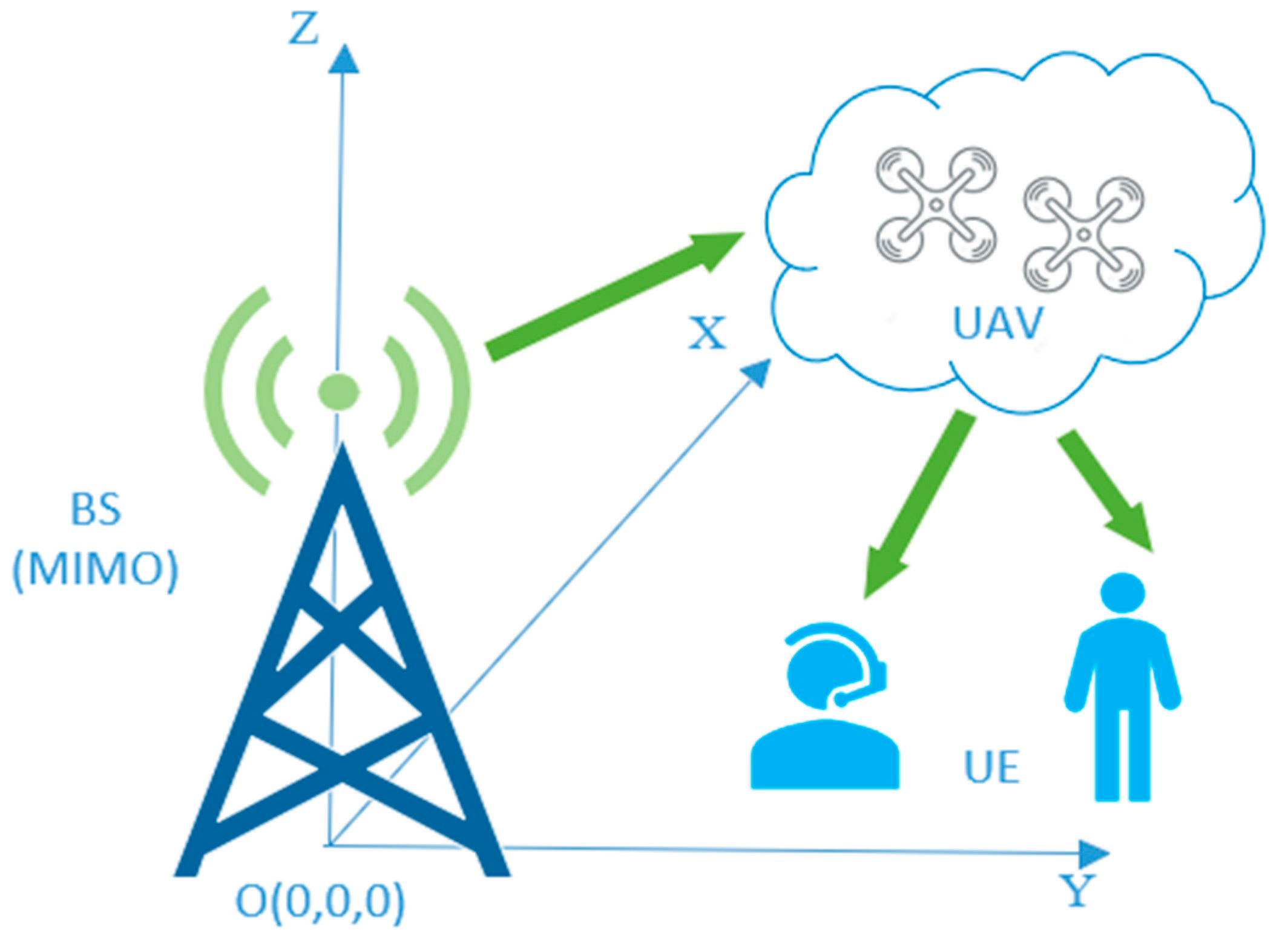
The simulation scenarios of DT-based UAV network are shown in Figure 7. The provided parameter values represent characteristics and specifications of a communication system involving antenna elements, beamwidth, gain, physical separation, bandwidth, carrier frequency, transmit power range, channel path loss index, AWGN spectral density, and noise figure. The communication system utilizes 512 antenna elements arranged in a 3-dimensional array with dimensions of 16 × 16 × 2. Each antenna element supports 256 elements per polarization. The beamwidth of the antenna is 90 degrees at −3 dB. The maximum gain of the antenna is 5 dBi. The physical separation between adjacent antenna elements is 0.5 wavelengths (λ). The communication system has a net transfer bandwidth of 800 MHz. The communication system operates at a carrier frequency of 100 GHz. The system’s transmit power can be adjusted within a range of 40–100 W. The channel path loss index is 3. The spectral density of AWGN in the channel is −170 dBm/Hz. The noise figure of the system is 5 dB.
Subsequently, simulation experiments are conducted on the proposed use cases (Use case 1: UAV flies along a straight line and Use case 2: UAV flies along a 30-degree inclined path). In each experiment, a comparative analysis is performed between the designed scheme and the finite-difference time-domain (FDTD) model to assess their respective performances. The use of actual radar measurements can be utilized to validate and verify the results obtained from the FDTD model.
“Use case 1: UAV flies along a straight line” represents a fundamental and commonly encountered scenario in UAV operations. In this case, the UAV follows a linear trajectory without any deviations, which allows us to study the basic channel characteristics and evaluate the impact of path loss and fading in a straightforward setting. Understanding the channel behavior in this scenario provides a foundation for comparison and benchmarking against more complex flight paths. On the other hand, “Use case 1: UAV flies along a 30-degree inclined path” introduces an essential element of real-world UAV applications, non-linear flight paths. Many practical UAV missions involve navigating through varying terrain, avoiding obstacles, or following specific routes for surveillance and data collection. By simulating an inclined path, we can investigate the effects of elevation changes on signal propagation, assess the impact of obstacles or terrain irregularities, and gain insights into the implications for communication link quality and performance. These chosen scenarios reflect crucial aspects of UAV networks in realistic operating conditions. By focusing on a straight-line flight and an inclined path, we cover both simple and complex flight trajectories, allowing us to draw meaningful conclusions about the UAV communication channel’s behavior across various operational scenarios. This approach enables us to design more robust communication protocols, antenna configurations, and network strategies tailored to the challenges presented by real-world UAV deployments. The combination of these distinct scenarios in our simulation analysis ensures that the derived channel model is practical, comprehensive, and capable of supporting the optimization of UAV network performance in diverse and dynamic environments.
The two approaches, actual radar imaging and FDTD models, can be employed to derive the channel model of UAVs. Both actual radar imaging and FDTD models can be employed to derive the channel model of UAVs. Actual radar imaging involves collecting real-world radar data and analyzing it to accurately describe the signal propagation characteristics, including path loss, multipath effects, and fading, between the radar transmitter and the UAV receiver. Despite its advantages in realism and comprehensiveness, this method may not be suitable for all scenarios due to its high cost, complexity, and limitations in results. On the other hand, FDTD models are numerical methods used to solve Maxwell’s equations and simulate electromagnetic wave propagation in a given environment. In the context of deriving the UAV channel model, FDTD models simulate the electromagnetic behavior between the radar transmitter and the UAV receiver based on the geometry of the surroundings. This approach offers advantages in flexibility and cost-effectiveness, as it can be applied to various scenarios and UAV configurations. However, FDTD models also have limitations, such as simplified assumptions and high computational requirements, which may result in some degree of accuracy loss. In practical applications, a combination of both approaches may be used to obtain a more comprehensive and accurate UAV channel model. Actual radar imaging provides valuable data for validating and calibrating the FDTD models, while FDTD models allow for exploring a wider range of scenarios and conditions without the constraints of physical experiments.

5.1. Use Case 1: UAV Flies along a Straight Line

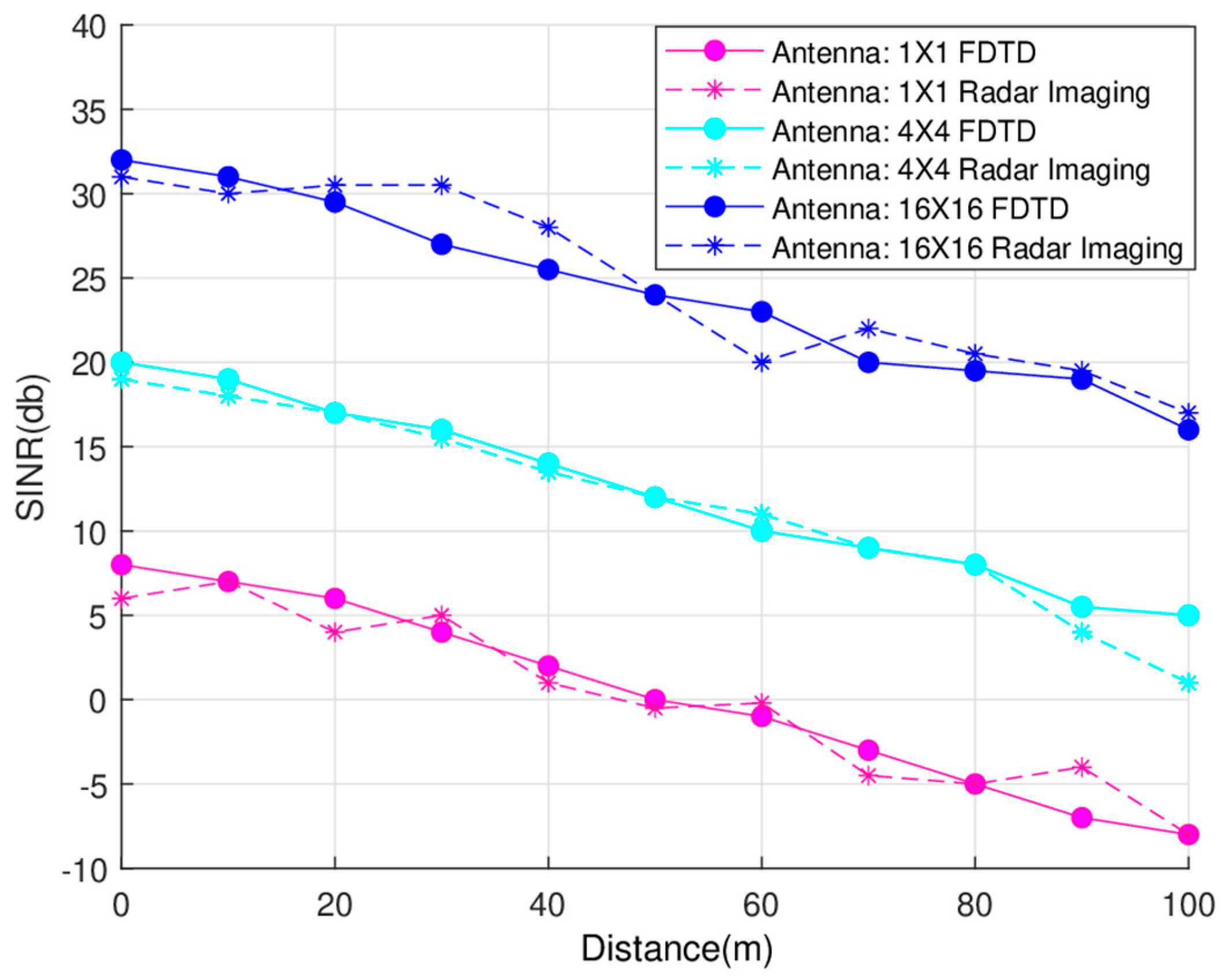
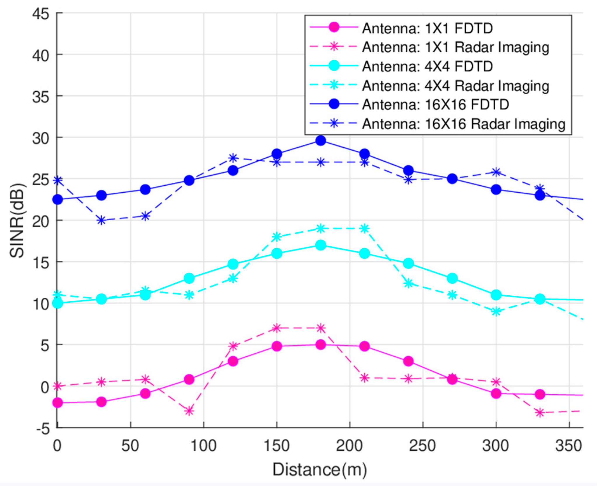
Figure 8 depicts the SINR as a function of the UAVs’ location or distance along a straight line for different numbers of transmit antennas: 1, 16, and 256 antennas, respectively. Notably, when the number of antennas is increased to 256, the beamforming gain experiences a substantial rise, resulting in a significant increase in SINR. The solid line in 
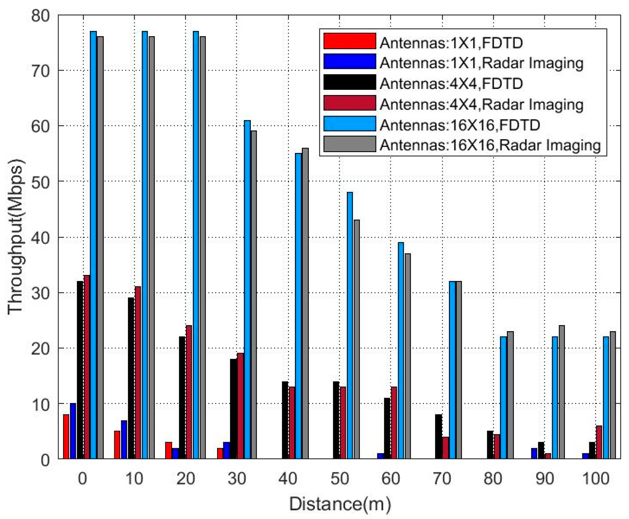
Figure 8 represents the SINR data obtained through the FDTD approach, while the dashed line corresponds to the results derived from RF imaging. Remarkably, the findings predominantly exhibit a close match, effectively capturing the correct trend, thus reaffirming their reliability and mutual consistency. In Figure 9, the relationship between throughput and the UAVs’ location is presented. The results demonstrate a close alignment between the data obtained through the FDTD method and the measured values. This compelling agreement validates the validity and soundness of our approach to radar imaging for RF digital twin modeling.

5.2. Use Case 2: UAV Flies along a 30-Degree Inclined Path

In 
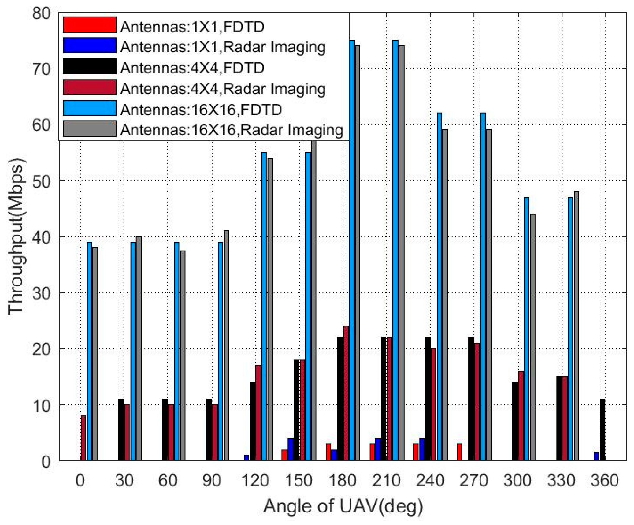
Figure 10, we present the SINR results, while Figure 11 showcases the throughput outcomes. The UAVs’ flight trajectory incorporates a 30-degree inclination angle, which introduces asymmetry in its distance from both the user equipment (UE) and the base station (BS). As a consequence of this asymmetry, the SINR and throughput results exhibit variations across the entire 360-degree range. The noticeable asymmetrical patterns in both figures underscore the significant influence of the UAVs’ flight angle on the communication system’s performance. These findings emphasize the importance of considering such flight angles in the design and evaluation of UAV communication systems, as they play a crucial role in determining overall communication quality and efficiency.
When comparing the results for straight and inclined path scenarios in UAV communication channel models, several patterns and differences emerge that reveal the impact of flight trajectories on signal propagation. In straight-line scenarios, changes in signal strength along a linear trajectory are attenuated. However, in oblique path scenarios, significant differences are observed. When the drone rises along a 30-degree slope, the signal strength roughly shows a trend of first rising and then falling. Understanding these patterns and differences is critical for designing adaptive communication strategies that can adapt to varying channel conditions, especially when UAVs traverse complex terrain or follow non-linear flight paths in real-world applications. By comparing the results of these different scenarios, researchers and engineers can gain insight into the performance constraints and opportunities for optimizing UAV communication networks under different operating conditions.
The validation process involving the use of actual radar measurements to validate and verify the results obtained from the FDTD model is a critical step in ensuring the accuracy and reliability of the simulated UAV communication channel. The process works by conducting real-world radar measurements in the same environment where UAVs operate. These measurements capture the actual electromagnetic behavior, including signal propagation, reflections, and scattering effects. The FDTD model is then used to simulate the same scenario by taking into account the same geometric parameters and frequency bands used during the radar measurements. By comparing the simulation results with the actual radar data, researchers can assess the accuracy of the FDTD model’s predictions. A close match between the simulation and real-world measurements indicates that the FDTD model accurately represents the UAV communication channel’s behavior, providing confidence in its application for designing and optimizing UAV communication systems. Furthermore, this validation process allows for model improvements based on discrepancies identified during comparison, enhancing the model’s reliability and its generalizability to different UAV scenarios and environments. Ultimately, the use of actual radar measurements for validation ensures that the FDTD model is a robust and reliable tool for supporting the development of efficient and effective UAV communication networks in real-world settings.

6. Conclusions

This study proposes a drone-enabled digital twin framework for green IoT that employs artificial intelligence to manage UAV swarm tasks, thereby accomplishing intelligent operation of physical UAV networks. The real-time DT-physical UAV connection permits optimal route planning and dependable UAV operation. 3D radar imaging extracts RF characteristics of UAVs for DT modeling. The application of ray-tracing to UAV propagation characteristics reflects their wireless channel influence. Finally, our numerical results justify that the drone-enabled DT platform faithfully represents UAV RF characteristics for intelligent management of green IoT-based UAV networks.

Author Contributions

Conceptualization, F.Q.; Visualization, L.L.; Methodology, T.H.; Validation, F.Z.; writing—original, F.Q.; writing—review and editing, W.X.; All authors have read and agreed to the published version of the manuscript.

Funding

This work was supported by National Key R&D Program of China (No. 2020YFB1806700).

Data Availability Statement

The data is internal company data, involves trade secrets and cannot 323 be shared.

Conflicts of Interest

The authors declare no conflict of interest.

References

  1. Liu, J.; Shi, Y.; Fadlullah, Z.M.; Kato, N. Space-Air-Ground Integrated Network: A Survey. IEEE Commun. Surv. Tutor. 2018, 20, 2714–2741. [Google Scholar] [CrossRef]
  2. Lin, X.; Rommer, S.; Euler, S.; Yavuz, E.A.; Karlsson, R.S. 5G from Space: An Overview of 3GPP Non-Terrestrial Networks. IEEE Commun. Stand. Mag. 2021, 5, 147–153. [Google Scholar] [CrossRef]
  3. Saad, W.; Bennis, M.; Chen, M. A Vision of 6G Wireless Systems: Applications, Trends, Technologies, and Open Research Problems. IEEE Netw. 2020, 34, 134–142. [Google Scholar] [CrossRef]
  4. Liu, B.; Wan, Y.; Zhou, F.; Wu, Q.; Hu, R.Q. Resource Allocation and Trajectory Design for MISO UAV-Assisted MEC Networks. IEEE Trans. Veh. Technol. 2022, 71, 4933–4948. [Google Scholar] [CrossRef]
  5. Huang, L.; Bi, S.; Zhang, Y.-J.A. Deep Reinforcement Learning for Online Computation Offloading in Wireless Powered Mobile-Edge Computing Networks. IEEE Trans. Mob. Comput. 2020, 19, 2581–2593. [Google Scholar] [CrossRef]
  6. Shen, G.; Lei, L.; Li, Z.; Cai, S.; Zhang, L.; Cao, P.; Liu, X. Deep Reinforcement Learning for Flocking Motion of Multi-UAV Systems: Learn from a Digital Twin. IEEE Internet Things J. 2022, 9, 11141–11153. [Google Scholar] [CrossRef]
  7. Alsharif, M.H.; Jahid, A.; Kelechi, A.H.; Kannadasan, R. Green IoT: A Review and Future Research Direc-tions. Symmetry 2023, 15, 757. [Google Scholar] [CrossRef]
  8. Albreem, M.A.; Sheikh, A.M.; Alsharif, M.H.; Jusoh, M.; Yasin, M.N.M. Green Internet of Things (GIoT): Applications, Practices, Awareness, and Challenges. IEEE Access 2021, 9, 38833–38858. [Google Scholar] [CrossRef]
  9. Alsharif, M.H.; Kim, S.; Kuruoğlu, N. Energy Harvesting Techniques for Wireless Sensor Net-works/Radio-Frequency Identification: A Review. Symmetry 2019, 11, 865. [Google Scholar] [CrossRef]
  10. Jiang, F.; Wang, K.; Dong, L.; Pan, C.; Xu, W.; Yang, K. AI Driven Heterogeneous MEC System with UAV Assistance for Dynamic Environment: Challenges and Solutions. IEEE Netw. 2021, 35, 400–408. [Google Scholar] [CrossRef]
  11. Dong, R.; She, C.; Hardjawana, W.; Li, Y.; Vucetic, B. Deep Learning for Hybrid 5G Services in Mobile Edge Computing Systems: Learn from a Digital Twin. IEEE Trans. Wirel. Commun. 2019, 18, 4692–4707. [Google Scholar] [CrossRef]
  12. Umeyama, A.Y.; Salazar-Cerreno, J.L.; Fulton, C.J. UAV-Based Antenna Measurements for Polarimetric Weather Radars: Probe Analysis. IEEE Access 2020, 8, 191862–191874. [Google Scholar] [CrossRef]
  13. Wu, Q.; Xu, J.; Zeng, Y.; Ng, D.W.K.; Al-Dhahir, N.; Schober, R.; Swindlehurst, A.L. A Comprehensive Overview on 5G-and-Beyond Networks with UAVs: From Communications to Sensing and Intelligence. IEEE J. Sel. Areas Commun. 2021, 39, 2912–2945. [Google Scholar] [CrossRef]
  14. Mihai, S.; Yaqoob, M.; Hung, D.V.; Davis, W.; Towakel, P.; Raza, M. Digital Twins: A Survey on Enabling Technologies, Challenges, Trends and Future Prospects. IEEE Commun. Surv. Tutor. 2022, 24, 2255–2291. [Google Scholar] [CrossRef]
  15. Bellavista, P.; Giannelli, C.; Mamei, M.; Mendula, M.; Picone, M. Application-Driven Network-Aware Digital Twin Management in Industrial Edge Environments. IEEE Trans. Ind. Inform. 2021, 17, 7791–7801. [Google Scholar] [CrossRef]
  16. Jia, P.; Wang, X.; Shen, X. Digital-Twin-Enabled Intelligent Distributed Clock Synchronization in Industrial IoT Systems. IEEE Internet Things J. 2021, 8, 4548–4559. [Google Scholar] [CrossRef]
  17. Minerva, R.; Lee, G.M.; Crespi, N. Digital Twin in the IoT Context: A Survey on Technical Features, Scenarios, and Architectural Models. Proc. IEEE 2020, 108, 1785–1824. [Google Scholar] [CrossRef]
  18. Motlagh, N.H.; Bagaa, M.; Taleb, T. UAV-Based IoT Platform: A Crowd Surveillance Use Case. IEEE Commun. Mag. 2017, 55, 128–134. [Google Scholar] [CrossRef]
  19. Karve, P.M.; Guo, Y.; Kapusuzoglu, B.; Mahadevan, S.; Haile, M.A. Digital twin Approach for Damage-tolerant Mission Planning Under Uncertainty. Eng. Fract. Mech. 2020, 225, 1–10. [Google Scholar] [CrossRef]
  20. Pan, C.; Chen, Y.; Wang, G. Virtual-Real Fusion with Dynamic Scene from Videos. In Proceedings of the International Conference on Cyber Worlds, Chongqing, China, 28–30 September 2016; IEEE Computer Society: Washington, DC, USA, 2016; pp. 65–72. [Google Scholar]
  21. Zhu, X.; Jiang, C. Integrated Satellite-Terrestrial Networks Toward 6G: Architectures, Applications, and Challenges. IEEE Internet Things J. 2022, 9, 437–461. [Google Scholar] [CrossRef]
  22. Ding, C.; Wang, J.-B.; Zhang, H.; Lin, M.; Li, G.Y. Joint Optimization of Transmission and Computation Resources for Satellite and High Altitude Platform Assisted Edge Computing. IEEE Trans. Wirel. Commun. 2022, 21, 1362–1377. [Google Scholar] [CrossRef]
  23. Gapeyenko, M.; Petrov, V.; Moltchanov, D.; Andreev, S.; Himayat, N.; Koucheryavy, Y. Flexible and Reliable UAV-Assisted Backhaul Operation in 5G mmWave Cellular Networks. IEEE J. Sel. Areas Commun. 2018, 36, 2486–2496. [Google Scholar] [CrossRef]
  24. Xiao, Z.; Zhu, L.; Liu, Y.; Yi, P.; Zhang, R.; Xia, X.-G.; Schober, R. A Survey on Millimeter-Wave Beamforming Enabled UAV Communications and Networking. IEEE Commun. Surv. Tutor. 2022, 24, 557–610. [Google Scholar] [CrossRef]
  25. Liu, X.; Liu, Z.; Zhou, M. Fair Energy-Efficient Resource Optimization for Green Multi-NOMA-UAV Assisted Internet of Things. IEEE Trans. Green Commun. Netw. 2021, 7, 904–915. [Google Scholar] [CrossRef]
  26. Song, M.; Huo, Y.; Liang, Z.; Dong, X.; Lu, T. Air-to-Ground Large-Scale Channel Characterization by Ray Tracing. IEEE Access 2022, 10, 125930–125941. [Google Scholar] [CrossRef]
  27. Bai, L.; Huang, Z.; Cui, L.; Cheng, X. A Non-Stationary Multi-UAV Cooperative Channel Model for 6G Massive MIMO mmWave Communications. IEEE Trans. Wirel. Commun. 2023. [Google Scholar] [CrossRef]
  28. To, L.; Bati, A.; Hilliard, D. Radar Cross Section measurements of small Unmanned Air Vehicle Systems in non-cooperative field environments. In Proceedings of the 2009 3rd European Conference on Antennas and Propagation, Berlin, Germany, 23–27 March 2009; pp. 3637–3641. [Google Scholar]
  29. Altin, N.; Yazgan, E. The Calculation of Back Scattering Field of Unmanned Air Vehicle. In Proceedings of the PIERS, Beijing, China, 23–27 March 2009; pp. 1460–1463. [Google Scholar]
  30. Abushakra, F.; Jeong, N.; Elluru, D.N.; Awasthi, A.K.; Kolpuke, S.; Luong, T.; Reyhanigalangashi, O.; Taylor, D.; Gogineni, S.P. A Miniaturized Ultra-Wideband Radar for UAV Remote Sensing Applications. IEEE Microw. Wirel. Compon. Lett. 2022, 32, 198–201. [Google Scholar] [CrossRef]
  31. Li, C.J.; Ling, H. An Investigation on the Radar Signatures of Small Consumer Drones. IEEE Antennas Wirel. Propag. Lett. 2017, 16, 649–652. [Google Scholar] [CrossRef]
  32. Chen, V.C.; Martorella, M. Inverse Synthetic Aperture Radar Imaging:Principles, Algorithms, and Applications; SciTech Publishing: Raleigh, NC, USA, 2014. [Google Scholar]
Figure 1. DJI Phantom 4 Pro UAV measurement environment.
Drones 07 00562 g001
Figure 2. A 3D physical model of quad-rotor UAVs for green IoT.
Drones 07 00562 g002
Figure 3. Digital Twin-Based Intelligent UAV Networks.
Drones 07 00562 g003
Figure 4. Windowing procedure.
Drones 07 00562 g004
Figure 5. Measurement of DJI Phantom 4 Pro UAVs (10 GHz) with Windowing procedure, (a) is HH Polarized two-dimensional image. (b) is VV Polarized two-dimensional image.
Drones 07 00562 g005
Figure 6. 3D Ray-tracing at mmWave Band for UAVs.
Drones 07 00562 g006
Figure 7. Simulation Setup of Digital-Twin-Based UAV Networks.
Drones 07 00562 g007
Figure 8. SINR vs. UAV Location.
Drones 07 00562 g008
Figure 9. Throughput vs. UAV Location.
Drones 07 00562 g009
Figure 10. SINR vs. UAV Angle (30-degree inclined path).
Drones 07 00562 g010
Figure 11. Throughput vs. UAV Angle (30-degree inclined path).
Drones 07 00562 g011
Disclaimer/Publisher’s Note: The statements, opinions and data contained in all publications are solely those of the individual author(s) and contributor(s) and not of MDPI and/or the editor(s). MDPI and/or the editor(s) disclaim responsibility for any injury to people or property resulting from any ideas, methods, instructions or products referred to in the content.

