1. Introduction
In recent years, with the improvement of technology and the reduction in production costs, UAVs are playing an increasingly important role in our daily lives. In the communications field, UAVs can support various military and civil services. With appropriate Internet of Things (IoT) or communication devices, several IoT applications can be created for UAVs [
1,
2,
3,
4].
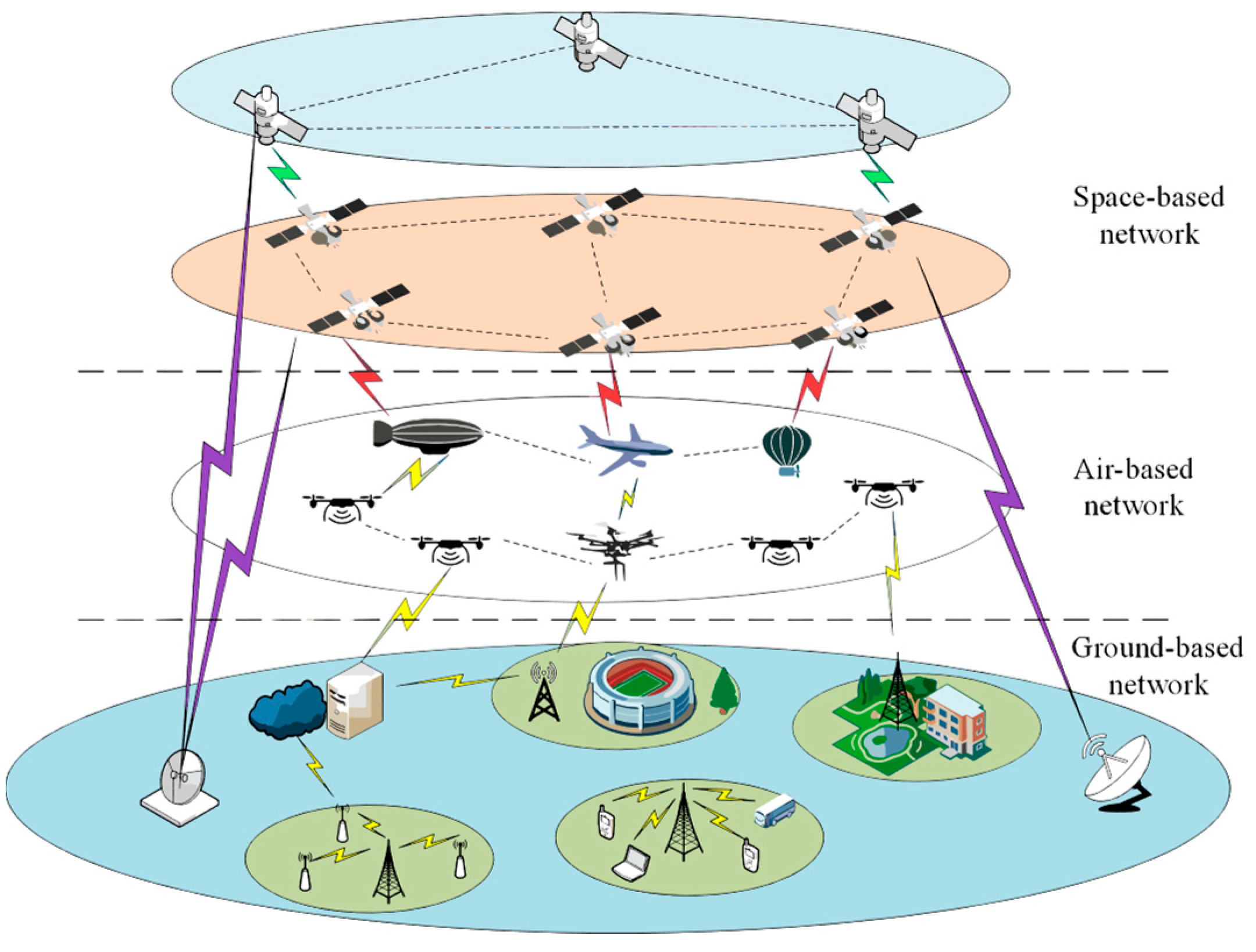
As shown in
Figure 1, UAVs equipped with communication devices and the latest communication technologies are essential components of the space–air–ground (SAG) IoT. These drones enable them to operate in a wide range of maritime, air, international (cross-border), and remote areas. They provide node-to-node information exchange at any time [
5].
However, those uncontrolled or registered UAVs that are prohibited from flying in designated airspace are called “illegal drones”. Illegal drones seriously affect our daily lives and even constitute crimes. Therefore, identifying small UAVs represented by multi-rotor UAVs has important application value. The uniqueness of UAVs is that almost all UAVs have one or more propellers. In 2003, renowned American scholar Victor C. Chen proposed the micro-Doppler effect [
6]. The rotation of the propeller blades causes periodic frequency modulation of the backscattered radar signal, generating sidebands on both sides of the UAV’s own Doppler spectrum. This additional Doppler frequency modulation is called the micro-Doppler effect [
7]. Extracting the instantaneous frequency parameters of each micro-Doppler signal component obtains the micro-motion characteristics of the UAV target’s micro-motion structure, which can provide a powerful means for UAV detection and identification [
8].
Svante Björklund et al. proposed using a small radar to collect micro-Doppler data (from the internal motion of the target), extract physical characteristics from the time velocity map of the data, and use them in Boosting classifiers to distinguish between categories of “human”, “animal”, and “artificial object” [
9]. These classifiers have recently received widespread attention and achieved a 90% correct classification rate for the current data’s classification results. Boosting classifiers are simple, easy to learn, and easy to use. They use radar to measure small drones and birds [
10], extract physical characteristics from TVDs (time velocity maps), and use enhanced classifiers to distinguish between drones and birds (target detection) and drone types (target classification). Xin Fang et al. studied the micro-Doppler feature analysis and extraction of small, unmanned rotorcraft (SUR) [
11]. Beom Seok Oh proposed a method for extracting the micro-Doppler characteristics of unmanned aerial vehicles based on empirical mode decomposition (EMD) [
12]. Song et al. proposed a micro-Doppler feature extraction method for multi-rotor UAVs based on the time-frequency concentration index. On the basis of the generalized Warblet transform (GWT) [
13], they proposed the time-frequency concentration as a quantitative analysis index and defined the concentration of the time-frequency (CTF). The problem of extracting micro-Doppler characteristics is transformed into finding the maximum value of the CTF in the transform domain, which can be solved using optimization methods. Compared with existing micro-Doppler estimation methods, this method has high computational efficiency, essentially meets the real-time requirements of actual engineering and the estimation accuracy of micro-motion targets’ micro-motion feature parameters is high [
14]. Therefore, this paper adopts this method and focuses on which optimization method is more effective in solving the problem of finding the maximum value of the CTF in the transform domain.
Commonly used intelligent optimization algorithms include the simulated annealing algorithm, genetic algorithm, ant colony algorithm, and particle swarm optimization (PSO) algorithm. Among them, the simulated annealing algorithm usually requires a higher initial temperature, a slower cooling rate, a lower termination temperature, and sufficient sampling times to find the optimal solution, and the optimization calculation time is too long. The genetic algorithm takes the coding of decision objects as the operation object, which is not suitable for solving continuous numerical problems. The ant colony algorithm is also not suitable for continuous numerical problems, and the algorithm itself is more complicated, has long search times, and is prone to stagnation [
15]. The particle swarm optimization algorithm proposed by Kennedy et al. in 1995 has the advantages of concise concepts, easy parameter adjustment, high computational efficiency, and good optimization accuracy. Therefore, it is widely used to solve optimization problems in various real-life fields [
16,
17,
18,
19]. However, as the complexity of optimization problems increases, the optimization efficiency of traditional PSO algorithms becomes increasingly low. For example, when solving complex multimodal testing problems, the PSO algorithm exhibits premature convergence and is prone to falling into local optima [
20,
21,
22,
23]. The particle swarm algorithm can solve continuous numerical optimization problems, and the optimization speed is faster than that of other methods. In the PSO algorithm, each particle in the population represents a potential solution to the problem to be optimized, where the particle state is represented by the velocity and position vectors. The main purpose of updating strategies in the PSO algorithm during particle evolution is to drive the population to approach the global optimal solution. However, when there are multiple local optima around the global optimal solution, the population may fall into local optima during flight [
24,
25,
26,
27]. Therefore, improving parameters or redesigning evolutionary mechanisms on the basis of the traditional particle swarm algorithm to improve the diversity of the population and the accuracy of the optimized solution is a problem that needs to be solved.
The authors of this article conducted research in the early stages and published some academic achievements [
28,
29,
30,
31], accumulating experience to solve this problem.
This paper adopts the competitive learning particle swarm optimization (CLPSO) algorithm to solve the problem of micro-Doppler feature extraction in order to reduce the probability of falling into local optima, slow extraction speed, and low accuracy when using conventional optimization methods such as the PSO algorithm. Through simulation and experimental comparison, it further demonstrates that the new algorithm used in this article is more effective.
The organizational structure of this article is as follows:
Section 2 is a theoretical derivation of existing and improved methods, and the conclusions are preliminarily verified through simulation;
Section 3 conducts practical tests on the improvement method proposed in this article and further demonstrates the effectiveness of the improvement through comparison;
Section 4 is a summary of the article; and
Section 5 is a discussion and outlook on the field of drone recognition.
2. Theoretical Derivation and Simulation Verification
2.1. Echo Model of Rotary-Wing Unmanned Aerial Vehicles
For high-resolution radar, the main rotor of a UAV can be thought of as a network of scattering points. Each scattering point modulates the amplitude and phase of radar waves before reflecting and recombining them into radar echoes. A UAV’s main rotor blades are simplified as a straight line in the modeling of micro-Doppler models [
32].
Figure 2 depicts the position of a scattering point on the radar and the target. The radar is located at point
O, and the rotation center of the UAV’s main rotor is located at point
O’.
The initial distance between them is , the distance from the scattering point P on the main rotor to the rotation center is , the length of the main rotor is l, the angular velocity of the UAV’s main rotor is , and the initial rotation angle is . The angle between the main rotor blade and the X’ axis is = t + .
Generally, the distance between a UAV’s target and radar is much greater than
. For a UAV moving with radial velocity
v, the angle shown in the above figure is
; the distance
from the scattering point
P on its main rotor to the radar can be approximated as follows:
The radar echo of scattering point
P is:
The radar echo of a single UAV’s main rotor can be obtained by removing the carrier frequency
from Equation (3) and integrating
over the length
L of the main rotor blade.
where
is the Doppler frequency shift of the UAV,
,
=
t +
, and
represents the non-normalized Sink function. Then, the radar echo of the main rotor consisting of
n blades is:
where
,
.
From the above expression, it can be seen that the radar echo of a UAV’s main rotor shows periodic sink function flicker in the time domain, and the flicker period is related to the rotation speed of the main rotor and the number of main rotor blades.
The radar echo model of a UAV’s main rotor can be obtained by superimposing the radar echoes of several main rotors [
32].
where
;
k = 0, 1, 2, …;
N − 1; and
m = 1, 2, …,
m.
M represents the number of main rotors,
n represents the number of blades of a single main rotor,
represents the radar carrier wavelength,
represents the distance from the radar to the
m-th main rotor rotation center,
represents the height of the
m-th main rotor rotation center relative to the radar, and
represents the pitch angle of the radar to the
m-th main rotor center.
After pulse compression and compensation of radar echoes, the analytic signal expression of the micro-Doppler components in the echoes can be obtained as:
The multiple rotors on a UAV can be equivalent to the superposition of the above formula in the radar echo.
The micro-Doppler signal of a UAV is a non-stationary periodic oscillating signal. The Rotating Fourier Transform can be used to analyze the micro-Doppler signal.
2.2. Micro-Doppler Extraction of Unmanned Aerial Vehicles Based on Time-Frequency Concentration
Song Chen et al. proposed a micro-Doppler feature extraction method for multi-rotor UAVs based on the time-frequency concentration index [
14]. This method is proposed based on the generalized Warblet transform, and the highlight is that it transforms the micro-Doppler feature extraction of multi-rotor UAVs into a parameter estimation problem for multi-component micro-Doppler signals. By analyzing the mapping relationship between the micro-Doppler characteristics of multi-rotor UAVs and multi-component micro-Doppler signals, Song Chen et al. proposed the time-frequency concentration as a quantitative analysis index. In the same time-frequency rotating domain, there are differences in the time-frequency concentrations corresponding to different micro-motion components. Based on the time-frequency concentration index, the micro-Doppler feature extraction method for multi-rotor UAVs takes this as the criterion to achieve parameter estimation of the micro-Doppler effect on micro-motion components. Then, the micro-Doppler characteristics of multi-rotor UAVs are extracted using the mapping relationship.
The micro-Doppler signal of a UAV is a non-stationary periodic oscillating signal. The Rotating Fourier Transform can be used to analyze the micro-Doppler signal.
In the equations, represents the analytical signal of the compressed micro-Doppler echo component; represents a Gaussian window function with time width σ; , , and represent the amplitude and rotation frequency of each micro-motion component signal; represents the signal rotated along the time-frequency domain in the time window and i represents the i-th micro-Doppler component in the signal.
When the micro-motion component matches the kernel function, the spectrum is an impulse response. Expanding
yields:
Because is now an impulse response, = 0. A matching rotation operator can be constructed. When the rotation operator matches the true instantaneous frequency value of the corresponding micro-motion component, i.e., the frequency resolution of this micro-motion component reaches the minimum value 1/σ, and the corresponding spectral amplitude reaches the maximum value. Among them, can be mapped to the blade length, rotation speed, and initial phase of the corresponding micro-motion component, respectively, ,,.
The concentration of the time-frequency (CTF) is defined as:
where
represents a Gaussian window function with time width
. This index has the following characteristics: The more the constructed frequency rotation operator
matches the true time-frequency characteristics of the micro-Doppler signal, the larger the value of the time-frequency concentration index. When the parameters of the frequency rotation operator are equal to those of the micro-Doppler signal, the time-frequency concentration index reaches the maximum value. Thus, the problem of extracting micro-Doppler characteristics is transformed to find the maximum value of the CTF in the transform domain, which can be solved using optimization methods.
2.3. PSO Algorithm
The particle swarm optimization (PSO) algorithm proposed by Kennedy et al. in 1995 is widely used to solve various optimization problems [
33]. The particle swarm algorithm can solve continuous numerical optimization problems, and the optimization speed is faster than that of other methods. Therefore, the PSO algorithm is traditionally chosen to extract micro-Doppler characteristics [
34]. The updated formula for particles in the particle swarm algorithm is as follows:
where
v represents the particle velocity;
x represents the particle position;
w is the inertia weight, reflecting the influence of the particle’s historical velocity information on its current velocity;
and
are acceleration factors, representing the weights of the individual cognition part and the social part in influencing the velocity;
r is a random number ranging from 0 to 1;
is the optimal position of the particle in the optimization process; and
is the optimal position of all particles in the particle swarm optimization process.
Next, the steps and methods of using the traditional PSO algorithm to extract UAV parameters are simulated, and the process flow is shown in
Figure 3:
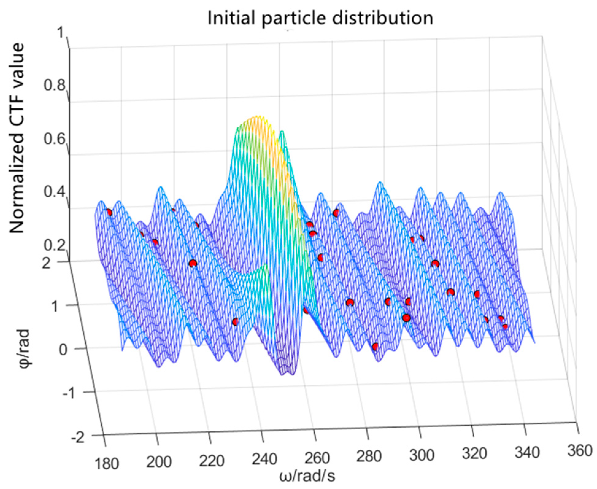
In the simulation, the rotor speed of the UAV is 40 revolutions per second, the rotor radius is 12 cm, the initial phase is 0, the distance between the UAV centroid and the radar beam center is 100 m, the radar carrier frequency is 34.6 GHz, the pulse frequency is 62.5 kHz, and the bandwidth is 1.2 GHz. One can bring these data into the calculation to obtain Sd(t) as the simulated UAV echo data and obtain the distribution of the maximum-value CTF particles, as shown in
Figure 4. Then, one can construct matching rotation factors within a reasonable parameter range and find the maximum value of the calculated time-frequency concentration. When using the PSO algorithm, the population size is set to 30, the maximum number of iterations is 100, the inertia weight
w = 0.729, the cognitive learning factor
= 2, and the social learning factor
= 2, as shown in
Figure 4 and
Figure 5.
From
Figure 4, we can see the problem of extracting micro-Doppler characteristics to be solved in this paper is a multi-peak problem. The disadvantages of traditional PSO algorithms when solving multi-peak problems are shown in
Figure 6a,b:
In case 1, when the optimal particle position of the individual is as shown in
Figure 6a, the other particles in the particle swarm will approach the optimal particle of the individual, and the individual optimal
of the particles will be far from the global optimum and close to the local optimum. The overall motion state of the particle swarm in the optimization process always follows the individual optimal position
and the global optimal position
, which will eventually lead the entire population to fall into the local optimal. In case 2, as shown in
Figure 6b, when the fitness value of the optimal particle of the individual is between the local and global optimal values, some particles in the population will enter the local optimal limitation by following the individual optimal position
and global optimal position
. In the optimization process, optimization stops before reaching
; even if some particles jump out of the local optimal, it will greatly lengthen the optimization time. Therefore, it is necessary to improve the traditional particle swarm algorithm to enhance the ability of the population to jump out of local optima.
2.4. CLPSO Algorithm
This paper adopts the competitive learning particle swarm optimization (CLPSO) algorithm to solve the problem of micro-Doppler feature extraction. The CLPSO algorithm divides the population into three subgroups with different optimization mechanisms by dynamically dividing the population based on the fitness of each particle. This approach enhances the local search ability of the algorithm and effectively reduces the probability of particles getting trapped in local optima when solving multi-peak problems [
35].
The CLPSO algorithm divides all of the particles into three groups based on their fitness. The particles whose fitness is greater than the average fitness by one standard deviation or more are the preferred area particles, the particles whose fitness is less than the average fitness by one standard deviation or more are the alienated area particles, and the other particles whose fitness is less than one standard deviation are the reasonable area particles. , and are used to represent the particles located in the preferred area, reasonable area, and alienated area, respectively, and the particle optimization methods in different areas are different: the particles in the preferred area are updated through self-mutation to enhance population diversity; the particles in the alienated area take the particles in the optimized area as the learning goal, which saves convergence time; and the reasonable area particles compete and select between population and the optimal area particles. In this way, even if the population falls into the local optimum, some active particles will continue to update their state via self-mutation, which increases the probability of the algorithm jumping out of the local optimum.
For excellent particles, self-mutation is performed using the improved Cauchy formula. The updated formula is as follows:
where
is the parameter to control the variation range,
is the random number generated by the Cauchy distribution function, and
and
t represent the maximum number of iterations and the current number of iterations, respectively. These will decrease with the increase in iteration times, so the particles can jump out of the local optimum in the early stage and converge in time in the later stage.
For particles in the alienation zone,
where
,
and
are acceleration factors;
is a small positive number;
is the position of particles in the alienated area at the last moment;
is the center position of particles in the preferred area; and
is the center position of all particles. That is, the position of the particles in the alienated area is based on their original position, and the particles in the preferred area are primarily used as the learning object to update while being limited by the particles’ center position. This updating method causes the particles in the alienation area to converge quickly and controls the updating range, which improves the algorithm’s convergence.
The optimization of moderate particles needs to be discussed by categorizing whether the population has fallen into the local optimum.
When the population has not fallen into the local optimum, moderate particles adopt the optimization method of ordinary PSO algorithms to ensure convergence. When the population has fallen into the local optimum, that is, the particle fitness does not change with iteration, moderate particles use the same formula as excellent particles to update to increase the probability of jumping out of local optima.
The steps and methods for using the CLPSO algorithm to extract UAV parameters are simulated. The acceleration factors are taken as
= 0.7,
= 0.25, and
= 0.5, and the other parameters are exactly the same as when using the traditional PSO algorithm. The results are shown in
Figure 7.
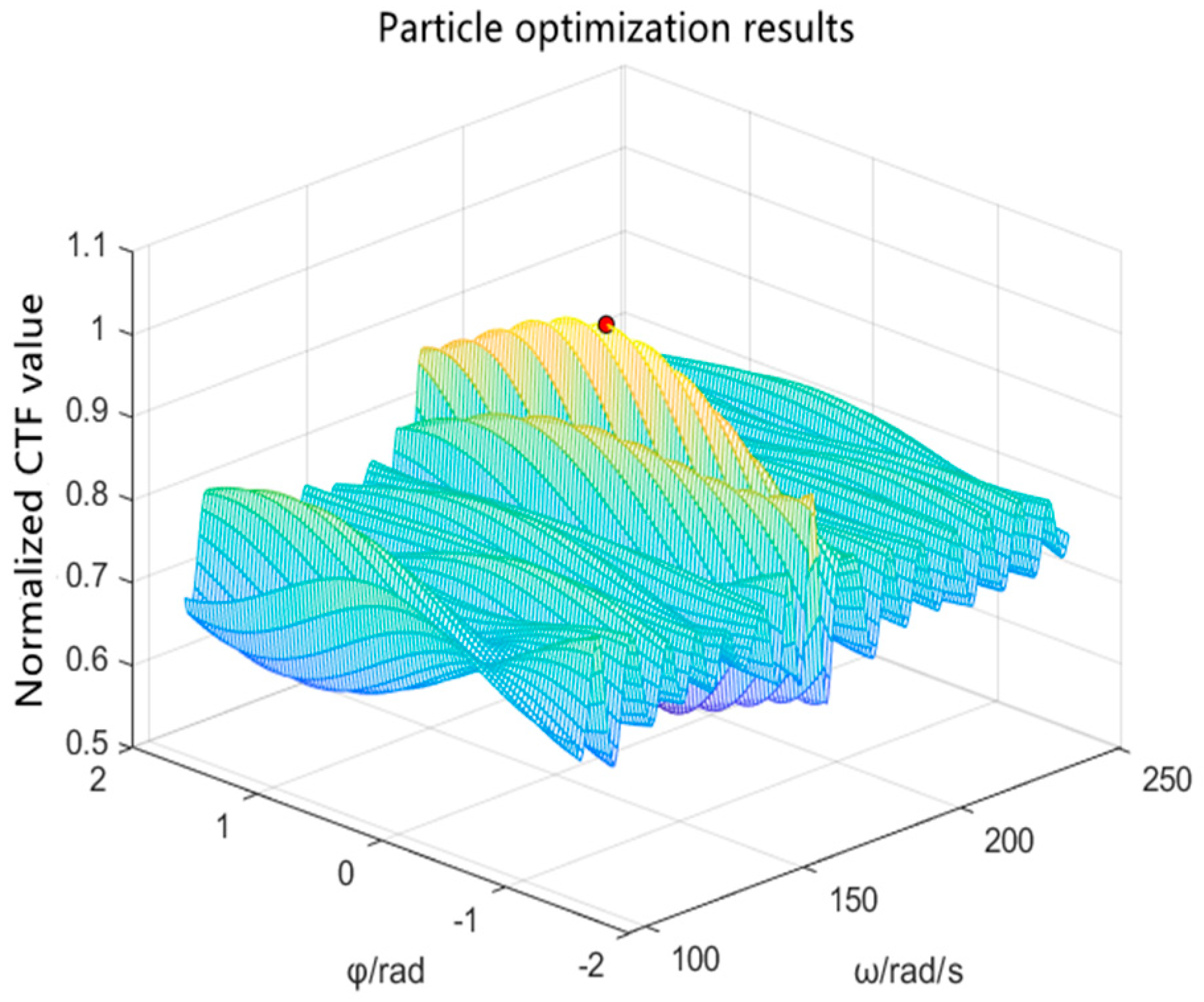
As can be seen from
Figure 7, the CLPSO algorithm can obtain the maximum point of the function. According to the results output by the CLPSO algorithm, the CTF value of the radar echo is the highest when the rotor speed is 251.123 (about 40
2
π) radians per second and the initial phase is 0.036, which is basically consistent with the UAV rotor parameters in the simulation. After repeated experiments, when using the CLPSO algorithm to solve the problem, there was no phenomenon in which the obtained parameters were inconsistent with the input due to falling into the local optimum, indicating that the accuracy was significantly improved compared with that of the PSO algorithm.
The particle fitness value is the normalized CTF value of the corresponding rotation operator, representing the degree of similarity between the rotation operator and the micro-motion component parameters in the radar echo. The convergence phenomenon at the suboptimal point occurs. Comparing the changes in fitness values with iteration times when using the CLPSO algorithm and the traditional PSO algorithm with the same simulation parameters, as shown in
Figure 8, the number of iterations when falling into local optima is reduced due to the self-mutation of excellent particles in the CLPSO algorithm using the improved Cauchy formula so that the CLPSO algorithm can converge faster compared with the PSO algorithm using the linear inertia weight.
3. Testing and Data Processing
Field measurement experiments were carried out to verify the effectiveness of the improved micro-Doppler effect extraction method based on time-frequency concentration. The experiment used the millimeter wave radar system firmware package manufactured by TEXAS INSTRUMENTS. The starting frequency of the radar subsystem was fixed at 77 GHz and supported a 4 GHz scanning bandwidth and a range resolution as low as 4 cm so that different rotors could be distinguished by adding distance gates. The specific parameter configuration of the radar during field testing was as follows: the radar starting frequency was 77 GHz, the frequency modulation slope was 29.982 MHz/μs, the number of sampling points was 256, the sampling frequency was 5 MHz, the pulse duration was 60 μs, and the pulse bandwidth was 1798.92 MHz. The test used three UAVs from different models. Since the radar firmware package used is a vehicle version with a limited effective working distance, the UAV flight height was about 2.5 m and the horizontal distance from the radar was about 2 m during the experiment. The flight parameters of the three UAVs are shown in
Table 1.
The experimental environment and testing situation of the field experiment are shown in
Figure 9.
The data were then used to compare the effects of the CLPSO algorithm and ordinary PSO algorithm, taking the radar echo data of a single-multi-rotor UAV as an example for analysis.
According to the collected data, the distance–slow time image of the radar echo was generated, with the horizontal and vertical coordinates being the sampling point numbers. Each sampling point on the horizontal coordinate represents 60 microseconds, each sampling point on the vertical coordinate represents 8.3 cm, as shown below, and the color temperature represents the intensity of the echo. Due to the influence of the micro-Doppler effect, the radar echo of the rotor was broadened in the frequency domain, and according to the imaging principle of frequency-modulated continuous wave radar, it was manifested as periodic expansion and contraction of the target volume in the range slow time image [
36].
According to the range–slow time image in
Figure 10, the distribution of the target’s CTF values was calculated and plotted, as shown in
Figure 11.
The radar echo data of the single-multi-rotor UAV collected during the field experiment were imported into the program. This was conducted to verify the feasibility of the improved UAV feature extraction technology based on the micro-Doppler effect proposed in this paper. When using the traditional PSO algorithm, it can normally converge to the maximum point in some cases, but it also converges to the sub-extreme point many times, as shown in
Figure 12,
Figure 13 and
Figure 14:
As can be seen from
Figure 15 and
Figure 16, the CLPSO algorithm can obtain the maximum point of the function. The corresponding rotor speed of the maximum value is 173.5 (about 27.6
2
π) radians per second, the initial phase is 0.183, and the extraction result is consistent with the data provided in the manual.
For the five groups of recorded experimental data, the maximum finding experiment was performed 10 times with two different algorithms. Among them, the ordinary PSO algorithm converged to the suboptimal point three times. When the results were correct, the average number of iterations for convergence was 15.4. When using the CLPSO algorithm, the results were all correct, and the average number of iterations for convergence was 11.2. This is superior to the traditional PSO algorithm in both accuracy and operational speed. The average fitness value change curve of the CLPSO algorithm and PSO algorithm when searching for the same data is shown in
Figure 17.
4. Discussion
The popularization of drones not only brings convenience to people’s lives but also poses a threat to safety. Technology to quickly and accurately identify drones at long distances without being limited by meteorological conditions has extremely high application value. During experimental data processing, the rotor parameters of a drone were extracted using the micro-Doppler effect-based identification method proposed in this paper, and the effectiveness of the method was verified. Then, the accuracy and iteration times of the traditional PSO algorithm and the CLPSO algorithm in extracting drone flight parameters were compared multiple times to verify that the CLPSO algorithm effectively improves accuracy and computational speed when applied to this identification method; this demonstrates the value of improving optimization algorithms. Based on the UAV feature extraction results obtained so far, the following aspects are worth further study:
(1) A large amount of UAV flight parameter data can be collected and stored in the database. After obtaining the UAV’s flight parameters, the system can compare the database data to identify the specific model of the UAV.
(2) When using optimization algorithms to find the maximum value of the concentration in the time-frequency rotation domain, AI algorithms can be considered to help narrow the parameter space and improve the accuracy and speed of solving.


