


An Efficient Framework for Autonomous UAV Missions in Partially-Unknown GNSS-Denied Environments
 , , , ,
  and
and 
Abstract
1. Introduction
1.1. Competition Details and Proposed System Overview
1.2. Related Works

| Reference | Wheelbase/ Weight | Flight Time | Companion Computer | FCU/ Autopilot | Sensors |
|---|---|---|---|---|---|
| Rojas-Perez et al. [19] | 47 ≈560 | <20 min | Odroid XU4 | Parrot Board Bebop Autopilot | Sensors from Parrot Bebop 2 |
| Kaufmann et al. [21] | 49 | N.S. | Aaeon UP Board | Qualcomm Snapdragon Flight N.S. | Intel RS R200 or Front-facing Camera |
| Li et al. [20] | 51 ≈400 | ≈12 min | Parrot P7 dual-core CPU Cortex A9 | Parrot Board Paparazzi | Sensors from Parrot Bebop 1 |
| Jung et al. [22] | 73 | 12 min | NVIDIA Jetson TK1 | In-house | ZED Stereo Camera LiDAR Lite V3 PX4FLow |
| Mohta et al. [25,26] | 75 ≈ | ≈5 min | Intel NUC i7 | Pixhawk 4 PX4 | 2 ×
FLIR Chamaleon VN-100 IMU LiDAR Lite V3 Hokuyo UTM-30LX * |
| Quigley et al. [27] | 40 ≈ | 15 min | NVIDIA Jetson TX2 | Pixhawk N.S. | FPGA with: 2 × 1300 Python Cameras 4 × Fish-eye Cameras |
| AlphaPilot [23] | 70 | N.S. | NVIDIA Jetson Xavier AGX | N.S. N.S. | 2 × Leopard IMX 264 IMU Bosch BMI088 LiDAR Lite V3 |
| Sandino et al. [30] | 73 Under 2 | 8 min | Aaeon UP Squared Board | Pixhawk 4 PX4 | Intel RS D435 Intel RS T265 HBV-1615 RGB camera TFMini Plus |
| Oleynikova et al. [28] | 70 ≈ | 15 min | Intel NUC i7 | mRo Pixhawk PX4 | VI Sensor ([35]) Intel RS D435 |
| Kompis et al. [29] | 75 ≈ ** | 15 min | Intel NUC i5/i7 or NVIDIA Jetson TX2 | Pixhawk 4 PX4 | Stereo VI Units ***: Intel RS D455 Alphasense Core Skybotix VI-Sensor ZED 2 Structure Core Venus RGB BlueFox |
| Campos-Macias et al. [32] | 59 | <20 min | Intel Atom x7-Z8750 | STM32F427V N.S. | Intel RS D435 Intel RS T265 |
| Roggi et al. [24] | 53 | ≈20 min | NVIDIA Jetson Xavier NX | Pixhawk 4 PX4 | ZED Stereo Camera 2 × OpenMV H7 Plus LiDAR Lite V3 |
| Stephens et al. [31] | 60 | ≈20 min | Intel NUC i7 | Pixhawk Pixracer PX4 | Intel RS D435i Intel RS T265 |
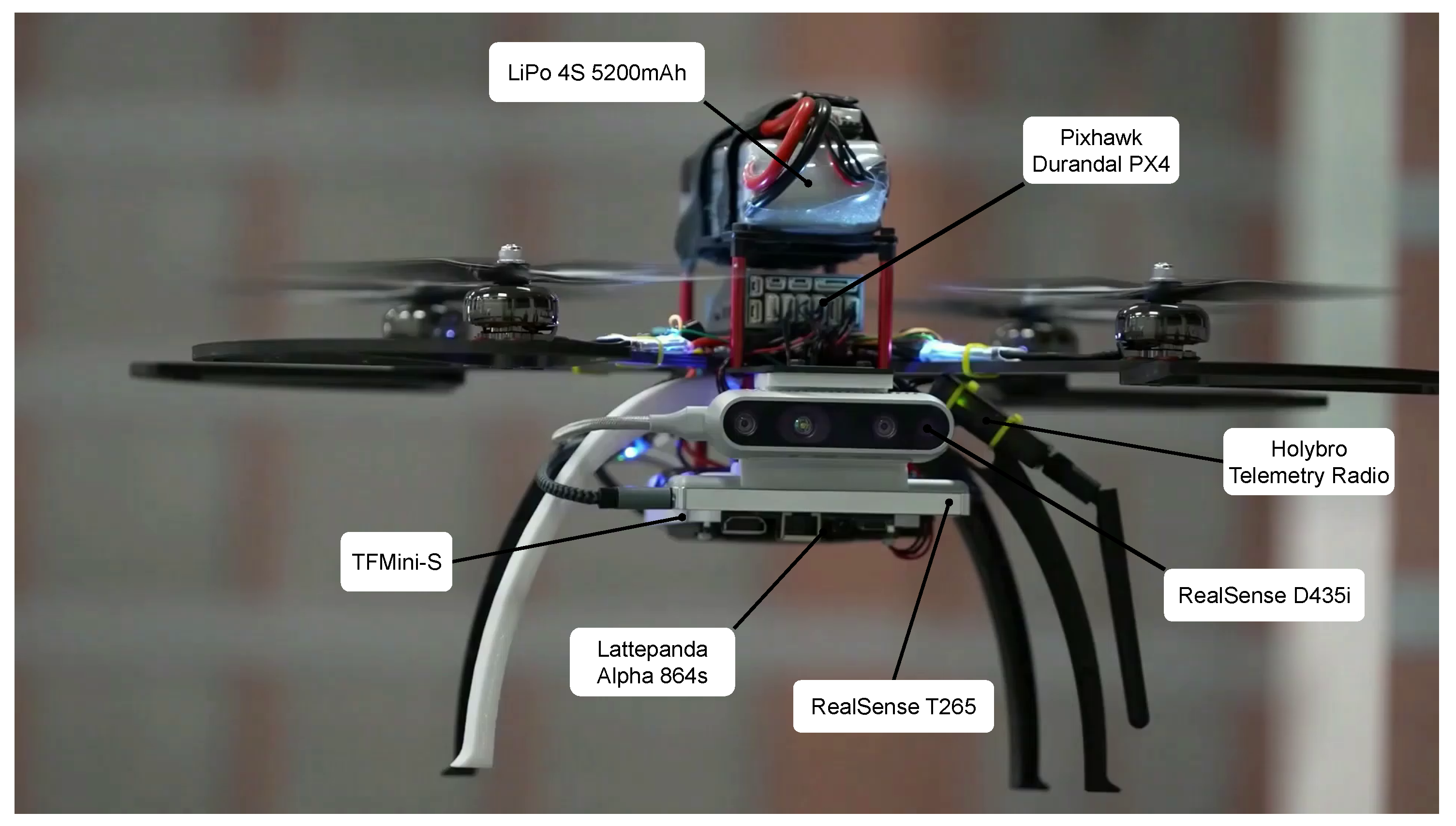
| our quadcopter | 54 | ≈12 min | Lattepanda Alpha 864s | Pixhawk Durandal PX4 | Intel RS D435i Intel RS T265 TFMini-S |
2. System Overview
2.1. Hardware Overview
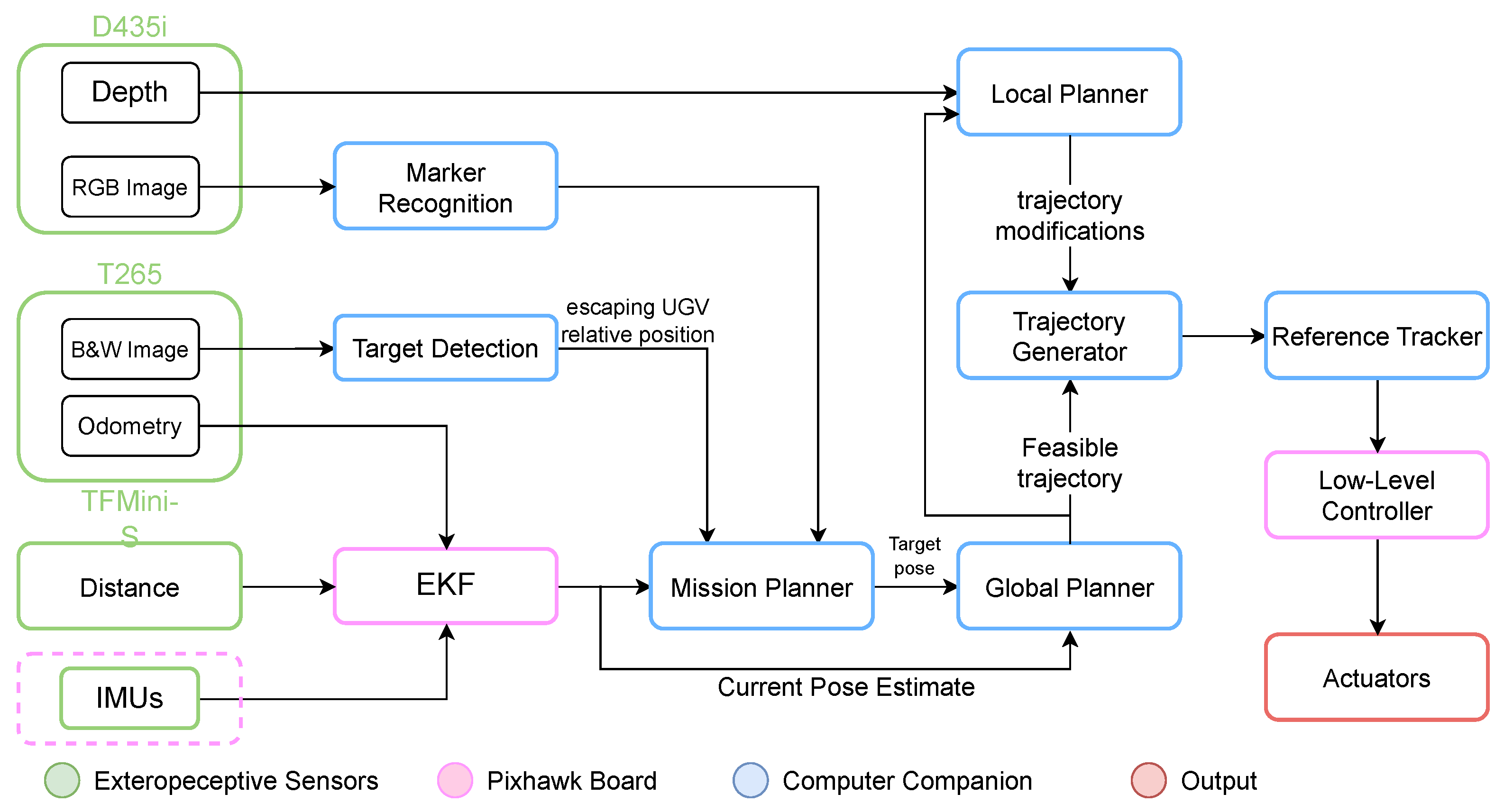
2.2. Software Overview
3. Core Modules of the Navigation Stack
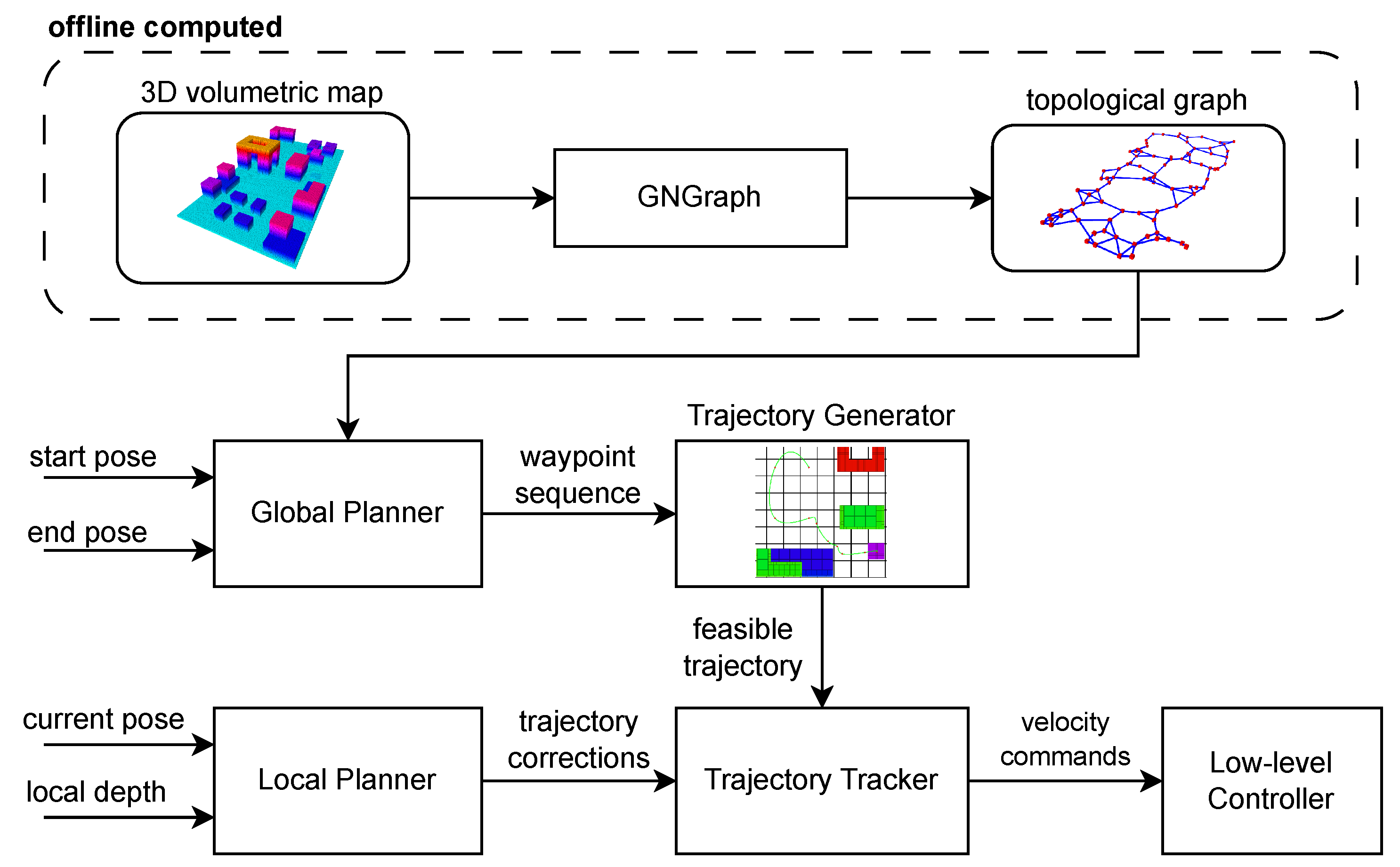
3.1. Offline Path Planning
3.2. Online Trajectory Planning
3.3. Local Planning for Obstacle Avoidance
3.4. Trajectory Reference Tracking and Low-Level Control
3.5. UGV Tracking
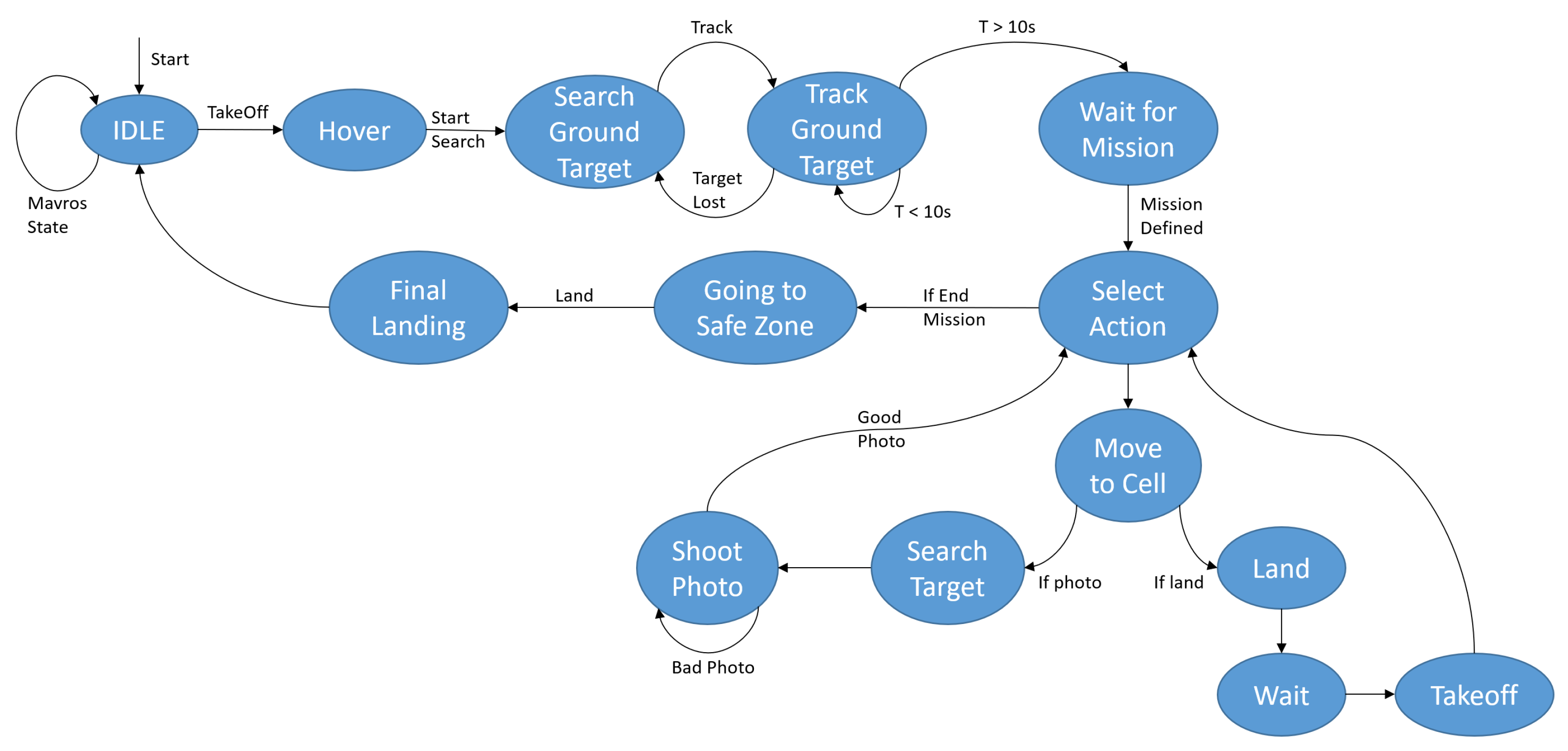
3.6. Mission Planner
4. Evaluation and Experiments
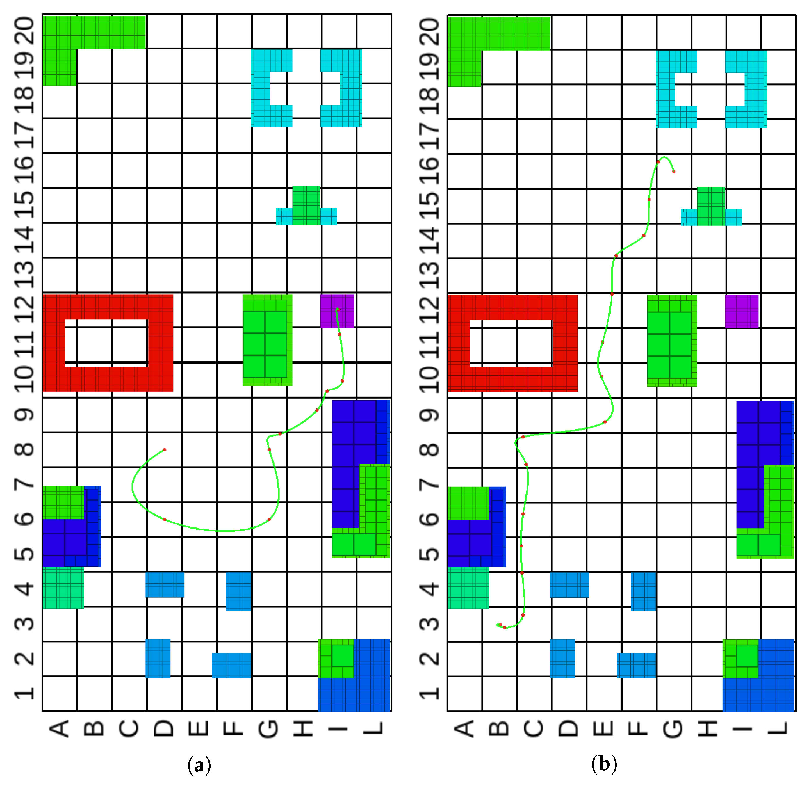
4.1. Global Trajectory Planner
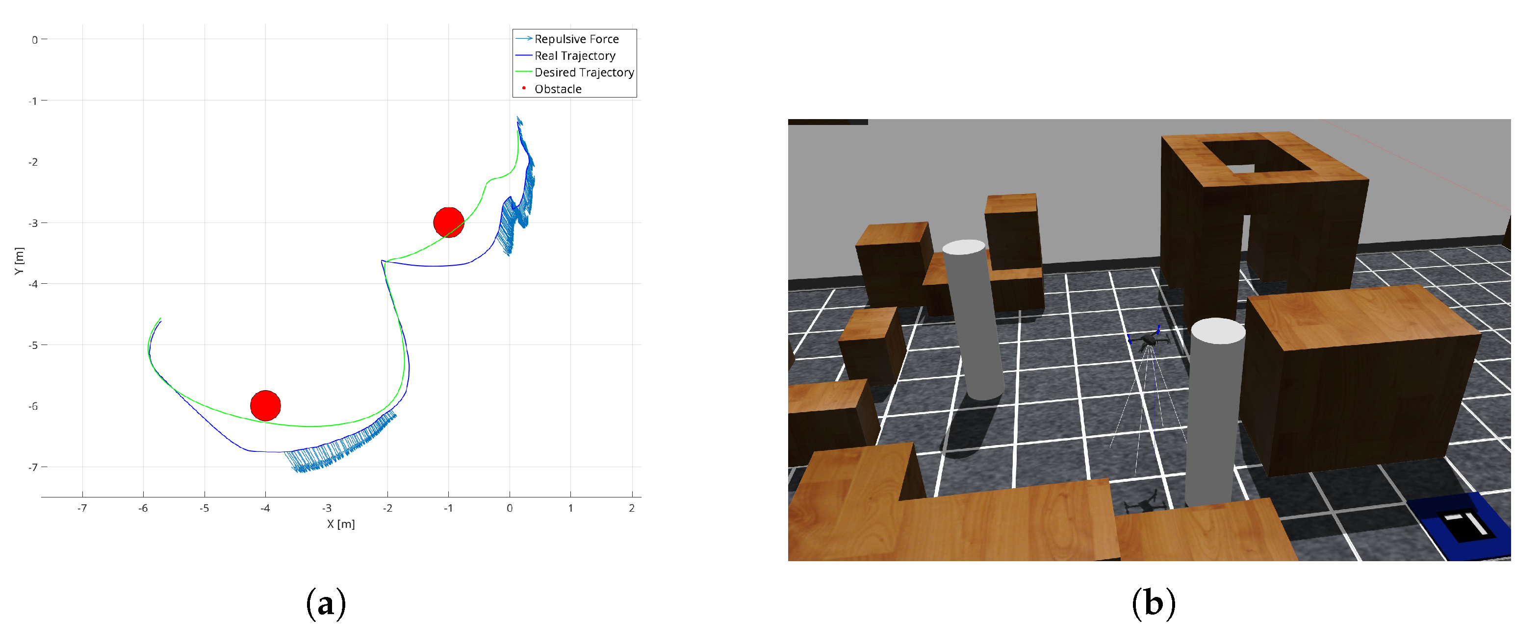
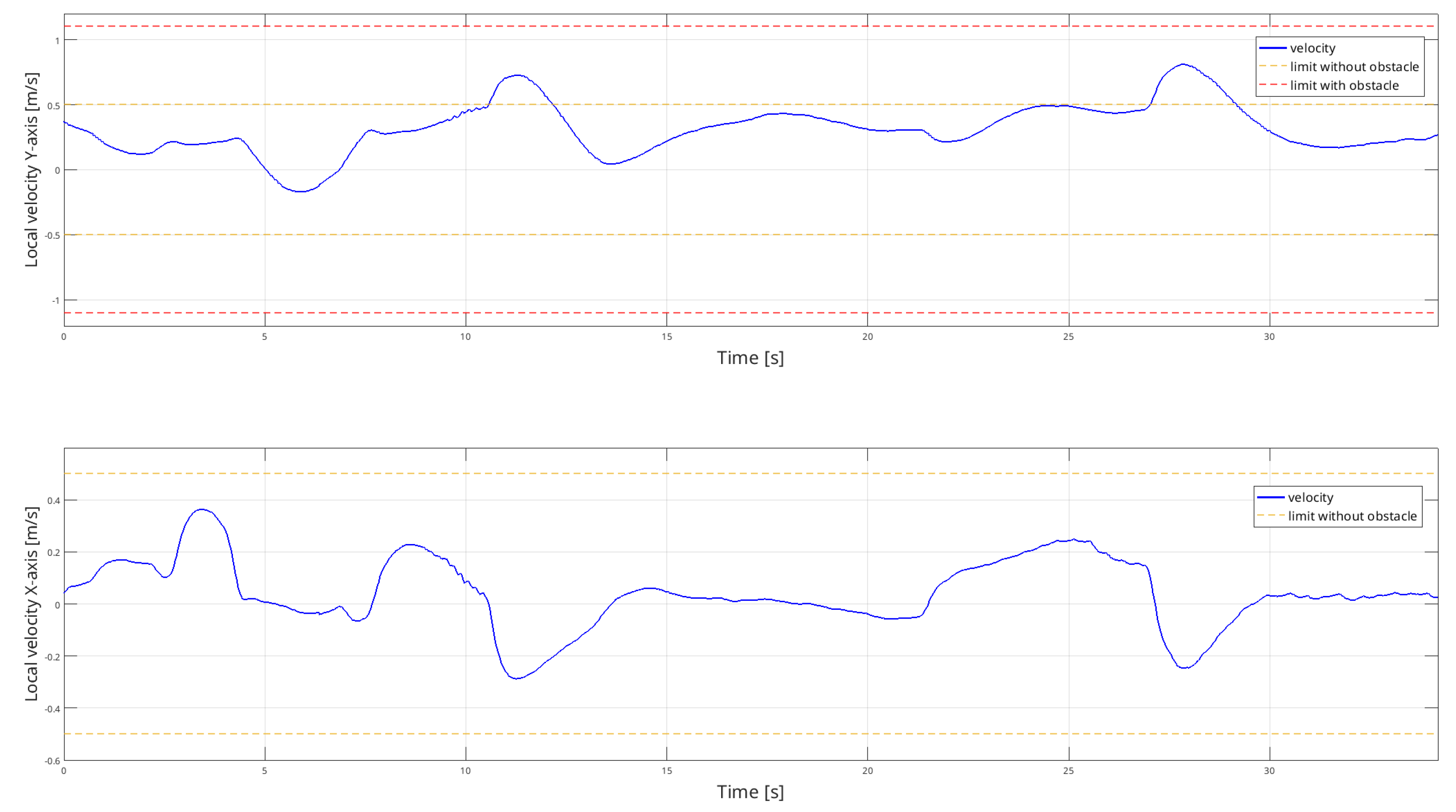
4.2. Local Planner
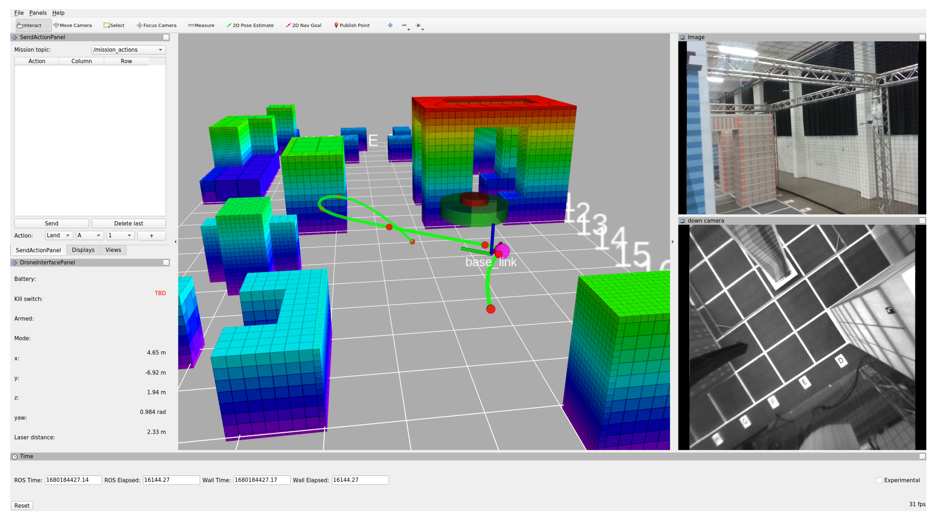
4.3. Overall System in Real Environment
5. Conclusions
Author Contributions
Funding
Data Availability Statement
Conflicts of Interest
Abbreviations
- The following abbreviations are used in this manuscript:
| UAV | Unmanned Aerial Vehicle |
| MAV | Micro-Aerial Vehicle |
| UGV | Unmanned Ground Vehicle |
| GNSS | Global Navigation Satellite System |
| ROS | Robot Operating System |
| RViz | ROS visualization tool |
| SAR | Search And Rescue |
| FSM | Finite State Machine |
| FCU | Flight Control Unit |
| FPGA | Field-Programmable Gate Array |
| RS | RealSense |
| LiDAR | Light Detection and Ranging |
| IMU | Inertial Measurement Unit |
| VIO | Visual Inertial Odometry |
| FOV | Field Of View |
| EKF | Extended Kalman Filter |
| TOPP | Time-Optimal Path Parametrization |
| APF | Artificial Potential Field |
| ESC | Electronic Speed Controller |
| GCS | Ground Control Station |
| GUI | Graphical User Interface |
References
- Silano, G.; Baca, T.; Penicka, R.; Liuzza, D.; Saska, M. Power Line Inspection Tasks with Multi-Aerial Robot Systems via Signal Temporal Logic Specifications. IEEE Robot. Autom. Lett. 2021, 6, 4169–4176. [Google Scholar] [CrossRef]
- Agha, A.; Otsu, K.; Morrell, B.; Fan, D.D.; Thakker, R.; Santamaria-Navarro, A.; Kim, S.K.; Bouman, A.; Lei, X.; Edlund, J.; et al. NeBula: Quest for Robotic Autonomy in Challenging Environments; TEAM CoSTAR at the DARPA Subterranean Challenge. arXiv 2021. [Google Scholar] [CrossRef]
- Hudson, N.; Talbot, F.; Cox, M.; Williams, J.; Hines, T.; Pitt, A.; Wood, B.; Frousheger, D.; Lo Surdo, K.; Molnar, T.; et al. Heterogeneous Ground and Air Platforms, Homogeneous Sensing: Team CSIRO Data61’s Approach to the DARPA Subterranean Challenge. Field Robot. 2022, 2, 595–636. [Google Scholar] [CrossRef]
- Rouček, T.; Pecka, M.; Čížek, P.; Petříček, T.; Bayer, J.; Šalanský, V.; Azayev, T.; Heřt, D.; Petrlík, M.; Báča, T.; et al. System for multi-robotic exploration of underground environments CTU-CRAS-NORLAB in the DARPA Subterranean Challenge. arXiv 2021. [Google Scholar] [CrossRef]
- Tranzatto, M.; Dharmadhikari, M.; Bernreiter, L.; Camurri, M.; Khattak, S.; Mascarich, F.; Pfreundschuh, P.; Wisth, D.; Zimmermann, S.; Kulkarni, M.; et al. Team CERBERUS Wins the DARPA Subterranean Challenge: Technical Overview and Lessons Learned. arXiv 2022. [Google Scholar] [CrossRef]
- Balaram, B.; Canham, T.; Duncan, C.; Grip, H.F.; Johnson, W.; Maki, J.; Quon, A.; Stern, R.; Zhu, D. Mars helicopter technology demonstrator. In Proceedings of the 2018 AIAA Atmospheric Flight Mechanics Conference, Kissimmee, FL, USA, 8–12 January 2018; p. 0023. [Google Scholar]
- Alarcón, E.P.H.; Ghavifekr, D.B.; Baris, G.; Mugnai, M.; Satler, M.; Avizzano, C.A. An Efficient Object-Oriented Exploration Algorithm for Unmanned Aerial Vehicles. In Proceedings of the 2021 International Conference on Unmanned Aircraft Systems (ICUAS), Athens, Greece, 15–18 June 2021; pp. 330–337. [Google Scholar] [CrossRef]
- Herrera-Alarcón, E.; Satler, M.; Vannucci, M.; Avizzano, C. GNGraph: Self-Organizing Maps for Autonomous Aerial Vehicle Planning. IEEE Robot. Autom. Lett. 2022, 7, 10721–10728. [Google Scholar] [CrossRef]
- Shen, S.; Michael, N.; Kumar, V. Autonomous multi-floor indoor navigation with a computationally constrained MAV. In Proceedings of the 2011 IEEE International Conference on Robotics and Automation, Shanghai, China, 9–13 May 2011; pp. 20–25. [Google Scholar] [CrossRef]
- Tomic, T.; Schmid, K.; Lutz, P.; Domel, A.; Kassecker, M.; Mair, E.; Grixa, I.; Ruess, F.; Suppa, M.; Burschka, D. Toward a fully autonomous UAV: Research platform for indoor and outdoor urban search and rescue. IEEE Robot. Autom. Mag. 2012, 19, 46–56. [Google Scholar] [CrossRef]
- Fraundorfer, F.; Heng, L.; Honegger, D.; Lee, G.H.; Meier, L.; Tanskanen, P.; Pollefeys, M. Vision-based autonomous mapping and exploration using a quadrotor MAV. In Proceedings of the IEEE International Conference on Intelligent Robots and Systems, Vilamoura-Algarve, Portugal, 7–12 October 2012; pp. 4557–4564. [Google Scholar] [CrossRef]
- Meier, L.; Tanskanen, P.; Heng, L.; Lee, G.H.; Fraundorfer, F.; Pollefeys, M. PIXHAWK: A micro aerial vehicle design for autonomous flight using onboard computer vision. Auton. Robot. 2012, 33, 21–39. [Google Scholar] [CrossRef]
- Meier, L.; Honegger, D.; Pollefeys, M. PX4: A node-based multithreaded open source robotics framework for deeply embedded platforms. In Proceedings of the IEEE International Conference on Robotics and Automation, Seattle, WA, USA, 26–30 May 2015; pp. 6235–6240. [Google Scholar] [CrossRef]
- Loianno, G.; Brunner, C.; McGrath, G.; Kumar, V. Estimation, Control, and Planning for Aggressive Flight With a Small Quadrotor With a Single Camera and IMU. IEEE Robot. Autom. Lett. 2017, 2, 404–411. [Google Scholar] [CrossRef]
- Ge, R.; Lee, M.; Radhakrishnan, V.; Zhou, Y.; Li, G.; Loianno, G. Vision-based Relative Detection and Tracking for Teams of Micro Aerial Vehicles. In Proceedings of the 2022 IEEE/RSJ International Conference on Intelligent Robots and Systems (IROS), Kyoto, Japan, 23–27 October 2022; pp. 380–387. [Google Scholar] [CrossRef]
- Thakur, D.; Tao, Y.; Li, R.; Zhou, A.; Kushleyev, A.; Kumar, V. Swarm of Inexpensive Heterogeneous Micro Aerial Vehicles. In Proceedings of the Experimental Robotics; Siciliano, B., Laschi, C., Khatib, O., Eds.; Springer International Publishing: Cham, Switzerland, 2021; pp. 413–423. [Google Scholar]
- Liu, X.; Chen, S.W.; Nardari, G.V.; Qu, C.; Ojeda, F.C.; Taylor, C.J.; Kumar, V. Challenges and Opportunities for Autonomous Micro-UAVs in Precision Agriculture. IEEE Micro 2022, 42, 61–68. [Google Scholar] [CrossRef]
- Moon, H.; Martinez-Carranza, J.; Cieslewski, T.; Faessler, M.; Falanga, D.; Simovic, A.; Scaramuzza, D.; Li, S.; Ozo, M.; De Wagter, C.; et al. Challenges and implemented technologies used in autonomous drone racing. Intell. Serv. Robot. 2019, 12, 137–148. [Google Scholar] [CrossRef]
- Rojas-Perez, L.O.; Martinez-Carranza, J. Metric monocular SLAM and colour segmentation for multiple obstacle avoidance in autonomous flight. In Proceedings of the 2017 Workshop on Research, Education and Development of Unmanned Aerial Systems (RED-UAS), Linköping, Sweden, 3–5 October 2017; pp. 234–239. [Google Scholar] [CrossRef]
- Li, S.; Ozo, M.M.; De Wagter, C.; de Croon, G.C. Autonomous drone race: A computationally efficient vision-based navigation and control strategy. Robot. Auton. Syst. 2020, 133, 103621. [Google Scholar] [CrossRef]
- Kaufmann, E.; Gehrig, M.; Foehn, P.; Ranftl, R.; Dosovitskiy, A.; Koltun, V.; Scaramuzza, D. Beauty and the Beast: Optimal Methods Meet Learning for Drone Racing. In Proceedings of the 2019 International Conference on Robotics and Automation (ICRA), Montreal, QC, Canada, 20–24 May 2019; pp. 690–696. [Google Scholar] [CrossRef]
- Jung, S.; Cho, S.; Lee, D.; Lee, H.; Shim, D.H. A direct visual servoing-based framework for the 2016 IROS Autonomous Drone Racing Challenge. J. Field Robot. 2018, 35, 146–166. [Google Scholar] [CrossRef]
- Foehn, P.; Brescianini, D.; Kaufmann, E.; Cieslewski, T.; Gehrig, M.; Muglikar, M.; Scaramuzza, D. AlphaPilot: Autonomous drone racing. Auton. Robot. 2022, 46, 307–320. [Google Scholar] [CrossRef]
- Roggi, G.; Meraglia, S.; Lovera, M. Leonardo Drone Contest 2021: Politecnico di Milano team architecture. In Proceedings of the 2022 International Conference on Unmanned Aircraft Systems, ICUAS 2022, Dubrovnik, Croatia, 21–24 June 2022; pp. 191–196. [Google Scholar] [CrossRef]
- Mohta, K.; Watterson, M.; Mulgaonkar, Y.; Liu, S.; Qu, C.; Makineni, A.; Saulnier, K.; Sun, K.; Zhu, A.; Delmerico, J.; et al. Fast, autonomous flight in GPS-denied and cluttered environments. J. Field Robot. 2018, 35, 101–120. [Google Scholar] [CrossRef]
- Mohta, K.; Sun, K.; Liu, S.; Watterson, M.; Pfrommer, B.; Svacha, J.; Mulgaonkar, Y.; Taylor, C.J.; Kumar, V. Experiments in Fast, Autonomous, GPS-Denied Quadrotor Flight. In Proceedings of the 2018 IEEE International Conference on Robotics and Automation (ICRA), Brisbane, QLD, Australia, 21–25 May 2018; pp. 7832–7839. [Google Scholar] [CrossRef]
- Quigley, M.; Mohta, K.; Shivakumar, S.S.; Watterson, M.; Mulgaonkar, Y.; Arguedas, M.; Sun, K.; Liu, S.; Pfrommer, B.; Kumar, V.; et al. The open vision computer: An integrated sensing and compute system for mobile robots. In Proceedings of the IEEE International Conference on Robotics and Automation, Montreal, QC, Canada, 20–24 May 2019; pp. 1834–1840. [Google Scholar] [CrossRef]
- Oleynikova, H.; Lanegger, C.; Taylor, Z.; Pantic, M.; Millane, A.; Siegwart, R.; Nieto, J. An open-source system for vision-based micro-aerial vehicle mapping, planning, and flight in cluttered environments. J. Field Robot. 2020, 37, 642–666. [Google Scholar] [CrossRef]
- Kompis, Y.; Bartolomei, L.; Chli, M. Fully Autonomous Live 3D Reconstruction with an MAV: Hardware- and Software-Setup, 2021-12-02. In Proceedings of the 9th International Conference on 3D Vision (3DV 2021), Online, 1–3 December 2021. [Google Scholar] [CrossRef]
- Sandino, J.; Vanegas, F.; Maire, F.; Caccetta, P.; Sanderson, C.; Gonzalez, F. UAV framework for autonomous onboard navigation and people/object detection in cluttered indoor environments. Remote Sens. 2020, 12, 3386. [Google Scholar] [CrossRef]
- Stephens, B.; Nguyen, H.N.; Hamaza, S.; Kovac, M. An Integrated Framework for Autonomous Sensor Placement With Aerial Robots. IEEE/ASME Trans. Mechatron. 2022, 28, 38–49. [Google Scholar] [CrossRef]
- Campos-Macías, L.; Aldana-López, R.; de la Guardia, R.; Parra-Vilchis, J.I.; Gómez-Gutiérrez, D. Autonomous navigation of MAVs in unknown cluttered environments. J. Field Robot. 2021, 38, 307–326. [Google Scholar] [CrossRef]
- Ko, C.; Han, S.; Choi, M.; Kim, K.S. Integrated path planning and tracking control of autonomous vehicle for collision avoidance based on model predictive control and potential field. In Proceedings of the 2020 20th International Conference on Control, Automation and Systems (ICCAS), Busan, Republic of Korea, 13–16 October 2020; pp. 956–961. [Google Scholar]
- Nieuwenhuisen, M.; Droeschel, D.; Beul, M.; Behnke, S. Autonomous navigation for micro aerial vehicles in complex GNSS-denied environments. J. Intell. Robot. Syst. 2016, 84, 199–216. [Google Scholar] [CrossRef]
- Nikolic, J.; Rehder, J.; Burri, M.; Gohl, P.; Leutenegger, S.; Furgale, P.T.; Siegwart, R. A synchronized visual-inertial sensor system with FPGA pre-processing for accurate real-time SLAM. In Proceedings of the 2014 IEEE International Conference on Robotics and Automation (ICRA), Hong Kong, China, 31 May–7 June 2014; pp. 431–437. [Google Scholar] [CrossRef]
- Werner, S.; Krieg-Brückner, B.; Herrmann, T. Modelling navigational knowledge by route graphs. In Spatial Cognition II; Springer: Berlin/Heidelberg, Germany, 2000; pp. 295–316. [Google Scholar]
- Mellinger, D.; Kumar, V. Minimum snap trajectory generation and control for quadrotors. In Proceedings of the IEEE International Conference on Robotics and Automation, Shanghai, China, 9–13 May 2011; pp. 2520–2525. [Google Scholar] [CrossRef]
- Pham, H.; Pham, Q.C. A New Approach to Time-Optimal Path Parameterization Based on Reachability Analysis. IEEE Trans. Robot. 2018, 34, 645–659. [Google Scholar] [CrossRef]
- Khatib, O. Real-time obstacle avoidance for manipulators and mobile robots. In Proceedings of the 1985 IEEE International Conference on Robotics and Automation, St. Louis, MO, USA, 25–28 March 1985; Volume 2, pp. 500–505. [Google Scholar]
- Furrer, F.; Burri, M.; Achtelik, M.; Siegwart, R. Rotors—A modular gazebo mav simulator framework. RObot Oper. Syst. Complet. Ref. 2016, 1, 595–625. [Google Scholar]


Disclaimer/Publisher’s Note: The statements, opinions and data contained in all publications are solely those of the individual author(s) and contributor(s) and not of MDPI and/or the editor(s). MDPI and/or the editor(s) disclaim responsibility for any injury to people or property resulting from any ideas, methods, instructions or products referred to in the content. |
© 2023 by the authors. Licensee MDPI, Basel, Switzerland. This article is an open access article distributed under the terms and conditions of the Creative Commons Attribution (CC BY) license (https://creativecommons.org/licenses/by/4.0/).
Share and Cite
Mugnai, M.; Teppati Losé, M.; Herrera-Alarcón, E.P.; Baris, G.; Satler, M.; Avizzano, C.A. An Efficient Framework for Autonomous UAV Missions in Partially-Unknown GNSS-Denied Environments. Drones 2023, 7, 471. https://doi.org/10.3390/drones7070471
Mugnai M, Teppati Losé M, Herrera-Alarcón EP, Baris G, Satler M, Avizzano CA. An Efficient Framework for Autonomous UAV Missions in Partially-Unknown GNSS-Denied Environments. Drones. 2023; 7(7):471. https://doi.org/10.3390/drones7070471
Chicago/Turabian StyleMugnai, Michael, Massimo Teppati Losé, Edwin Paúl Herrera-Alarcón, Gabriele Baris, Massimo Satler, and Carlo Alberto Avizzano. 2023. "An Efficient Framework for Autonomous UAV Missions in Partially-Unknown GNSS-Denied Environments" Drones 7, no. 7: 471. https://doi.org/10.3390/drones7070471
APA StyleMugnai, M., Teppati Losé, M., Herrera-Alarcón, E. P., Baris, G., Satler, M., & Avizzano, C. A. (2023). An Efficient Framework for Autonomous UAV Missions in Partially-Unknown GNSS-Denied Environments. Drones, 7(7), 471. https://doi.org/10.3390/drones7070471