


Abstract
Since unmanned aerial vehicles (UAVs), such as drones, are used in various fields due to their high utilization and agile mobility, technologies to deal with multiple UAVs are becoming more important. There are many advantages to using multiple drones in a swarm, but, at the same time, each drone requires a strong connection to some or all of the other drones. This paper presents a superior approach for the UAV network’s routing system without wasting memory and computing power. We design a routing system called the geolocation ad hoc network (GLAN) using geolocation information, and we build an adaptive GLAN (AGLAN) system that applies reinforcement learning to adapt to the changing environment. Furthermore, we increase the learning speed by applying a pseudo-attention function to the existing reinforcement learning. We evaluate the proposed system against traditional routing algorithms.
1. Introduction
Unmanned aerial vehicles (UAV) were originally developed and used for military purposes, but as drone technology gradually develops, drones are becoming more popular and are being used in various fields [1]. There are various advantages in utilizing multiple drones as a swarm [2]. Since the UAV network generally covers a wide range of maps in a variety of environments, it is essential to ensure a strong connection between objects within the drone squadron. This connection allows the remote ground control unit to receive control messages and UAVs in the swarm to transmit messages to each other. However, the traditional routing algorithms have limitations because they do not guarantee several UAV characteristics, such as mobility, communication instability, lightweight equipment, and wireless communication [3]. In order to prevent data omission when transmitting and receiving UAV data and to reduce data transmission delays, it is necessary to establish an optimal routing algorithm suitable for the UAV environment [4]. In this case, it is possible to form an ad hoc network in which data can be transmitted via multiple unmanned moving objects [5]. Ad hoc routing methods use a UAV exchange link or node state data in the UAV network to obtain a routing path in order to send information to a specific UAV [6]. Ad hoc is suitable for an environment that utilizes a mobile host due to its mobility feature. It enables networks between mobile hosts in an environment where centralized management is not supported [7]. However, ad hoc routing can lead to unnecessary delays and frequent network partitioning, as each UAV is extremely mobile and the communication link is unstable, resulting in constantly changing routing paths for each pair of UAVs [8].
Location-based routing in ad hoc networks has the advantage of enabling efficient routing by using the geographical location information of nodes [9]. In this process, all transmission nodes deliver the data packet to their nearest neighbor node as the destination node. The periodic exchange of location information between UAVs is required to perform reliable routing. However, this process has two problems: the first is unnecessary energy consumption by nodes in areas where there is no data transfer, and the second is the inaccuracy of neighbor node location information at the time of data transfer [10]. The location-based routing algorithm proposed in this paper can cope with the large amount of communication, irregular mobility, and wide range of communication that occurs when operating multiple UAVs.
When multiple UAVs form a network with each other, numerous communications between UAVs can occur, which can burden the network and degrade the quality of communication [11]. In addition, UAVs have a characteristic in that the type of network and transmission path can be flexibly changed according to a given environment and task due to their high mobility [12]. In this case, additional communication between UAVs takes place. At this time, since each UAV establishes a new communication path in a different communication environment, it becomes more burdensome to build a network. If some UAVs in the cluster are accidentally located outside the network range, cluster network communication is disrupted and errors occur during transmission. In this paper, we propose a routing algorithm called the geolocation ad hoc network (GLAN) that minimizes the communication burden and adapts to the changing communication environment.
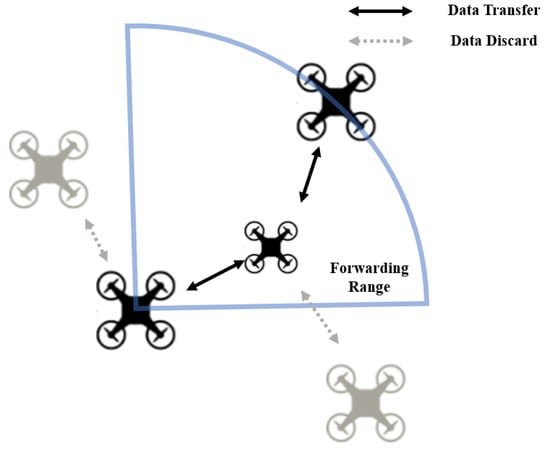
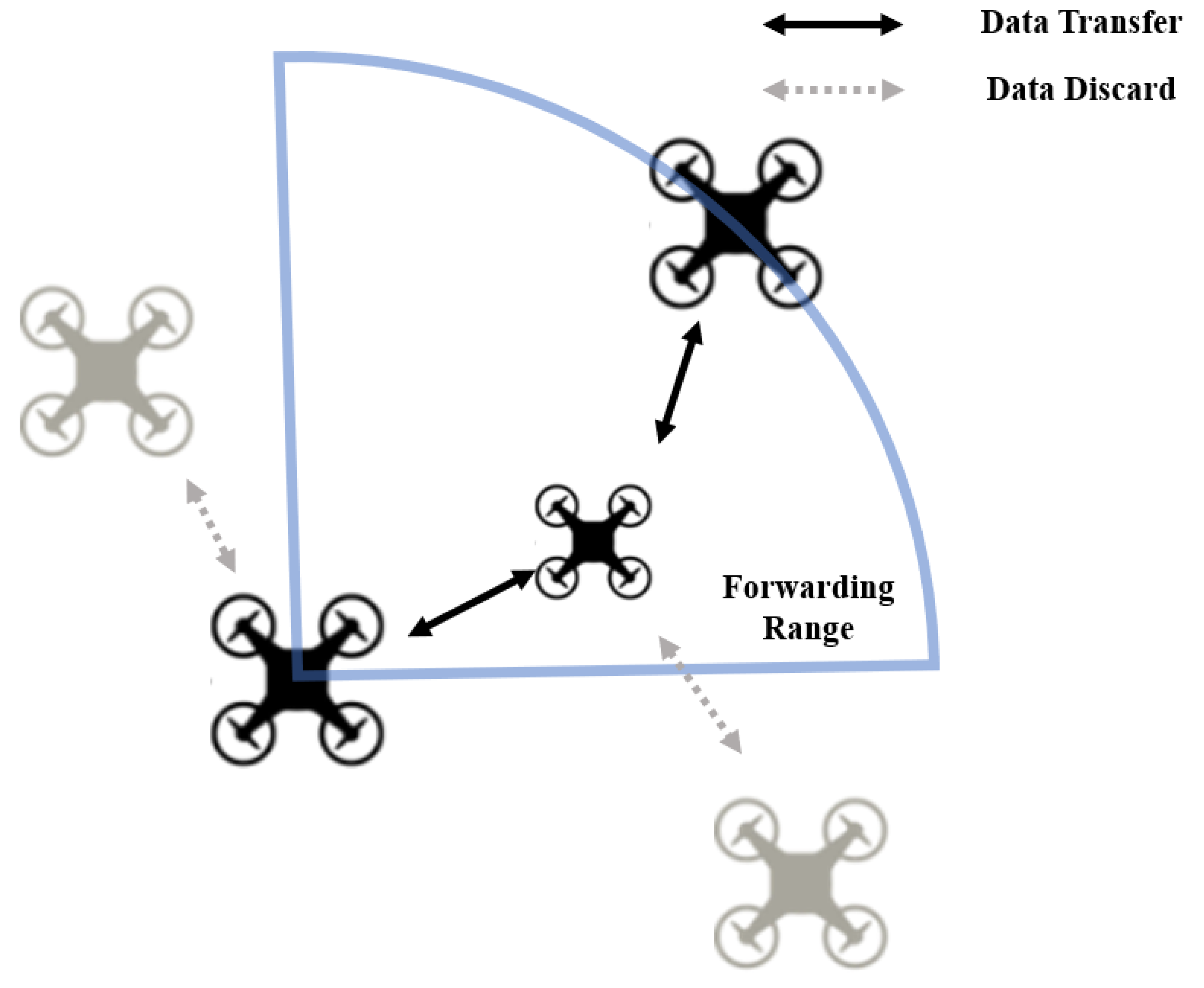
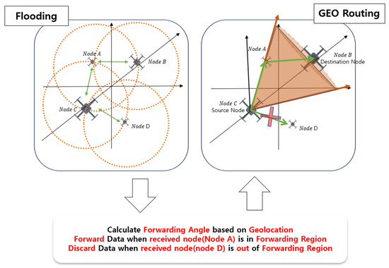
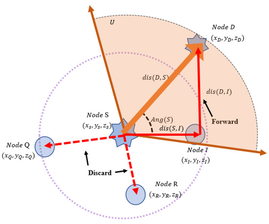
We construct an adaptive geographic ad hoc routing algorithm for UAV swarms based on location information. This routing protocol communicates through broadcasting, but by forwarding range settings learned using reinforcement learning (RL), routes are designed by connecting only the necessary links for data transmission, as shown in Figure 1.
Figure 1.
Forwarding system in GLAN.
The traditional routing method, LAR, is finite because it estimates the expected area using the last known destination location to reduce the search space for the desired route [13]. Our system continuously updates the location of the destination so that an accurate route can be set. GFG is performed in a greedy manner, forwarding packets to neighbors closer to the destination’s physical location; it can be repeated at intermediate nodes and overload the network [14]. GLAN enables optimized routing by learning the optimal path through simulation according to the given environment.
Compared to conventional mapping technologies, our proposed system has several advantages, as described below.
- Routing algorithm considering UAV characteristics. Previous approaches require the maintenance of routing tables to pass data, which can waste memory and power and can lead to network bottlenecks. This algorithm can deliver data in any environment, without a routing table, because all UAVs have IP settings related to geographic location information in consideration of mobility, which is a UAV characteristic.
- End-to-end principle preserved. Previously, when forwarding data, passing nodes needed to check whether they were the final destination of the data. The proposed system does not pass datagrams with the support of the application layer while changing the source and destination information. This means that our correspondence does not violate the end-to-end principle.
- Accurate delivery. The routing method used to deliver UAV data so far has been unable to solve communication problems that occur in the middle. However, since this system primarily delivers data through broadcasting, the probability of data being delivered to the destination is high; moreover, since it divides the forwarded area, data can be delivered accurately with less power.
The rest of this paper is organized as follows. In Section 2, we introduce the related research and show differences and similarities with our system. Then, we introduce the routing protocol design of our system in Section 3 and the RL approach on GLAN in Section 4. We describe our system’s performance and compare it with other algorithms in Section 5. Finally, Section 6 concludes the paper.
2. Related Work
In this section, we address the motivation and the major approaches to the system design. One major issue of the routing protocol between UAVs in a wireless network is that it is difficult to avoid delays on the network because of the altering positions of UAVs [15]. A minor delay between the sending and receiving of data can have a huge impact on the quality of the experience. Numerous network routing protocols have been proposed to solve this problem.
2.1. Location-Based Network
Location-based routing algorithms help to improve the QoE. Location-aided routing (LAR) is a method of broadcasting only in a limited area using the location information of the source node and the destination node [16]. It is assumed that each node knows its physical location using GPS. LAR operates by setting an expected area based on location information between a source node and a destination node to gradually reduce the flooding area. As a result, route request messages are less often sent to unnecessary locations, which can provide more resources for data transmission. LAR is an advantageous routing protocol for dense networks. Greedy Perimeter Stateless Routing (GPSR) involves transmitting data by selecting the node closest to the destination among the nodes in its transmission range using its location information [17]. This method delivers data through the most optimized path between the source and the destination. Each node configures the routing table by periodically sending notification messages to each other to maintain information between neighboring nodes. GPSR consists of only information on nodes within its transmission range, not information on the entire network. Therefore, since a message is not sent to the entire network when searching for a route, the number of cases in which a route request message is delivered to an unnecessary location is reduced. It is a routing protocol used to secure a minimum path from a source node to a destination node. Location-based network routing still causes unnecessary interruptions and overloads the network.
2.2. Ad Hoc Networking
Ad hoc networks are primarily used in changing environments and can be used to address the limitations of infrastructure networks [18]. They are suitable for cases in which it is difficult to construct a wired network or can be used for a short period after the network is constructed. Ad hoc networks have the advantage of fast network configuration and low costs, because there is no restriction on host movement and there is no need for wired networks and base stations [19].
The Optimized Link State Routing (OLSR) protocol is a routing method that maintains routing information for all destinations based on the link state and distance vector, calculates routes in advance, generates routing tables, and updates the routing tables after determined periods of time [20]. It is suitable for an ad hoc network with a large amount of location movement. However, it is not suitable for real-time communication because it requires a search of the entire network when a route is requested, and this may generate a large amount of control traffic. The Ad Hoc On-Demand Distance Vector (AODV) records the addresses and hops of the nodes passed by because the source node floods the packet to find a destination, floods it back to the neighboring nodes that received it, and then responds to the source node [21]. This routing protocol is a method that transmits data as a representative reactive routing protocol that sets a routing path only when the topology changes, and it does not set a routing path if data are not delivered. Ad Hoc Multicast Routing (AMRoute) and the Ad Hoc Multicast Routing Protocol Utilizing Increasing ID NumberS (AMRIS) are protocols in which the unique shortest path is determined from the source side to each destination and data are transmitted through it [22,23]. The On-Demand Multicast Routing Protocol (ODMRP) and Core-Assisted Mesh Protocol (CAMP) are protocols in which data are transmitted through one or more paths [24,25].
The Mobile Ad Hoc Network (MANET) and Flying Ad Hoc Network (FANET) consider mobility, which is the most important point for UAV communication [26,27]. MANET has the advantage that the network is decentralized and the devices are mobile. FANET is a protocol optimized to track the fast speeds of nodes and rapid network topology changes by using the concept of a routing protocol in MANET. The ad hoc network has a mobility feature because it uses mobile hosts, and this makes communication link instability worse.
2.3. Reinforcement Learning
Reinforcement learning (RL) is applied to various fields because it learns through experience, so it can solve highly complex problems without an accurate mathematical modeling process [28]. RL, which learns through trial and error to find goals, aims to learn weights and biases using the concept of rewards, similar to existing neural networks learning weights and biases through labeled data. In addition, deep reinforcement learning (DRL), which combines deep learning, has attracted interest among researchers in various fields because it has the ability to solve large-scale, complex problems [29].
RL is generally recognized as suitable for solving optimization problems related to the routing of distributed systems. Moreover, it is an efficient alternative to improve the online awareness of routing protocols in changing environments. Therefore, RL can be used to optimize resource utilization while providing a high level of QoS. Boyan and Littman first proposed a Q-learning-based hop-by-hop routing algorithm called Q-routing [30]. Q-Learning Modified AODV (QLMAODV) uses RL to optimize AODV for routing in MANETs [31]. The RL-Based Self-Routing Protocol (RLSRP) applies reinforcement learning to address rapid topology changes in FANETs consisting of flying nodes [32].
3. System Design and Algorithm
The following subsections discuss the concepts and details of geographic protocol design.
3.1. Concept of GLAN Protocol
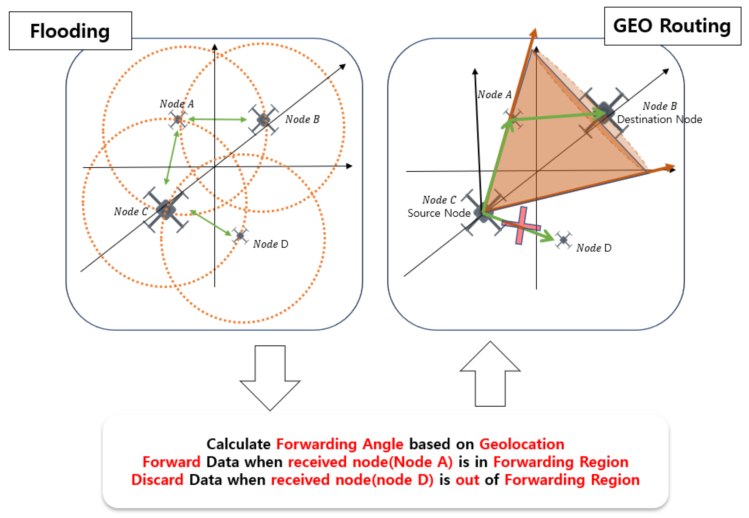
We constructed the GLAN protocol, overcoming traditional routing protocol and ad hoc network limitations, considering UAV characteristics. Figure 2 shows the concept of our proposed system. Our system advances from the flooding method, which was based on UAV routing. GLAN finds a forwarding region (FR) by computing a forwarding angle to form optimal routes from source nodes to destination nodes by utilizing geographic location information from each UAV. We optimize the calculated angles using RL and apply them to UAV systems. In the environment setting before learning, the mobility error for each episode is changed significantly so that the mobility characteristics of the UAV can be considered. The data requested for forwarding are delivered only when the UAV receiving the data is within the output angle area of the learning model. To check whether it is in the FR, the system obeys the end-to-end rule of data transmission by comparing only the IP addresses, rather than using the entirety of the received data.
Figure 2.
Concept of GLAN.
3.2. System Overview
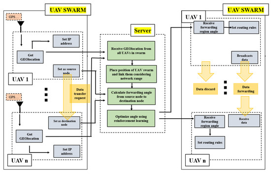
Figure 3 is an overall overview of the proposed system. Each UAV in the cluster extracts the geographic location from a sensor device such as GPS and converts the corresponding information into an IP address. Because UAVs can always determine their positions through positioning devices such as GPS, the algorithm proposed in this system can be used. Accordingly, the UAV can determine the IP address of another UAV in the cluster only by location information, without a routing table. After setting the IP address, the UAVs in the swarm form an ad hoc network. Through this process, the UAVs in the system are reliable and can communicate with each other much faster.
Figure 3.
The overall overview of the proposed system.
The UAVs in the swarm that is set up deliver geographic location information to the UAV server, and the server creates a 3D simulation environment containing the received location information. Since this system does not use a routing table for data transmission, it does not select a path to be transmitted but broadcasts to all nodes within the network scope. Each node verifies that the received data are its own data.
Since the broadcast method is used, data are transmitted to all neighboring nodes, and when each node broadcasts the transmitted data again, many unnecessary duplicate messages are transmitted. To solve this problem, our system sets the FR to determine whether the data are heading toward the destination through the previously created environment. In order to deliver data between UAVs in the cluster by the optimal route, the intermediate nodes check whether they are in the FR. The server calculates a forwarding angle that determines the FR through information on the start node, the arrival node, and the passing node. In addition, in order to further increase the probability of successful data transmission, the forwarding angle is learned in consideration of the characteristics of UAVs whose positions continuously change, so that there is no problem with data transmission even if the position deployed in the environment changes to a predictable extent. By limiting the forwarding area using the forwarding angle, the flooding packet is reduced, the packet can be trusted, and the packet can be transmitted efficiently.
The UAV server delivers the learned angle to all UAVs in the cluster, and each UAV sets routing rules by considering the location and angle of its own node according to the received angle. The established routing rules determine whether they are in the FR by considering their IP address, the IP address of the start node, and the IP address of the final destination node. If the node is in the FR, it continues to forward the data; otherwise, it discards the data. Through this process, the intermediate node can only serve as a router, reducing the time spent on data transmission and eventually reducing the network resources consumed. This system allows a drone in one location to exchange packets with a drone in another location without the need to run ad hoc routing. In addition, since broadcasting is used, data exchange is possible without a separate configuration or the exchange of information between UAVs, such as the link or node status, and the FR is optimized using RL to reduce unnecessary network resource consumption.
3.3. Geographic Protocol Design
When communicating through a UAV, a problem may occur if a communication protocol that does not consider the characteristics of the UAV is used. In particular, communication between UAVs can cause problems with data transfer beyond the network range, because the locations of drones change frequently. If the data to be sent are delivered through broadcasting, they can be delivered quickly at once, but this is not safe because it has a negative effect on the network bandwidth and anyone can receive the data. Conversely, if we communicate by setting a route, data can be transmitted safely and quickly, but a large overhead occurs when maintaining or re-establishing a routing table. A routing system suitable for UAV communication should safely transmit data, consider UAV mobility, and set a low network load. The protocol proposed in this paper reliably delivers data through broadcasting and forwarding. Our system reduces the network load and increases the reliability by adding routing rules, and it also considers the mobility characteristics of UAVs.
The network area is designed using the current location of the UAV so that the UAVs in the cluster can transmit and receive data through an optimal route. Longitude, latitude, and altitude information is obtained through a GPS sensor and the information is entered into the private A-class IP address of the connected network interface controller (NIC). Therefore, the IP addresses of all UAVs contain their own physical address information. UAVs in the swarm recognize each other’s location addresses to maintain the topology, so they can access the IP without the need for a separate routing table or re-establishment. Therefore, it is possible to reduce the overhead that occurs when maintaining or re-establishing a routing table required for data transmission.
All UAV addresses in the swarm are passed to the main UAV server, and the server builds a UAV squadron simulation environment using the location information. When a data transmission request comes from a UAV squadron, the server identifies the source and destination and calculates the FR angle through the GLAN algorithm in the simulation. The server delivers the calculated FR angle back to the swarm, and all UAVs in the cluster set routing rules according to the information received, to determine whether to forward or discard the received broadcast data. In particular, we use geolocation information to identify network addresses between UAVs in the swarm, to reduce the need to maintain routing tables and establish forwarding areas to enable efficient communication. Through this process, even if the UAV location changes and data are broadcasted, the network load can be reduced and reliable data can arrive safely.
3.4. GLAN Algorithm
For readability, we define the terminology used in this paper in Table 1.
Table 1.
GLAN terminology.
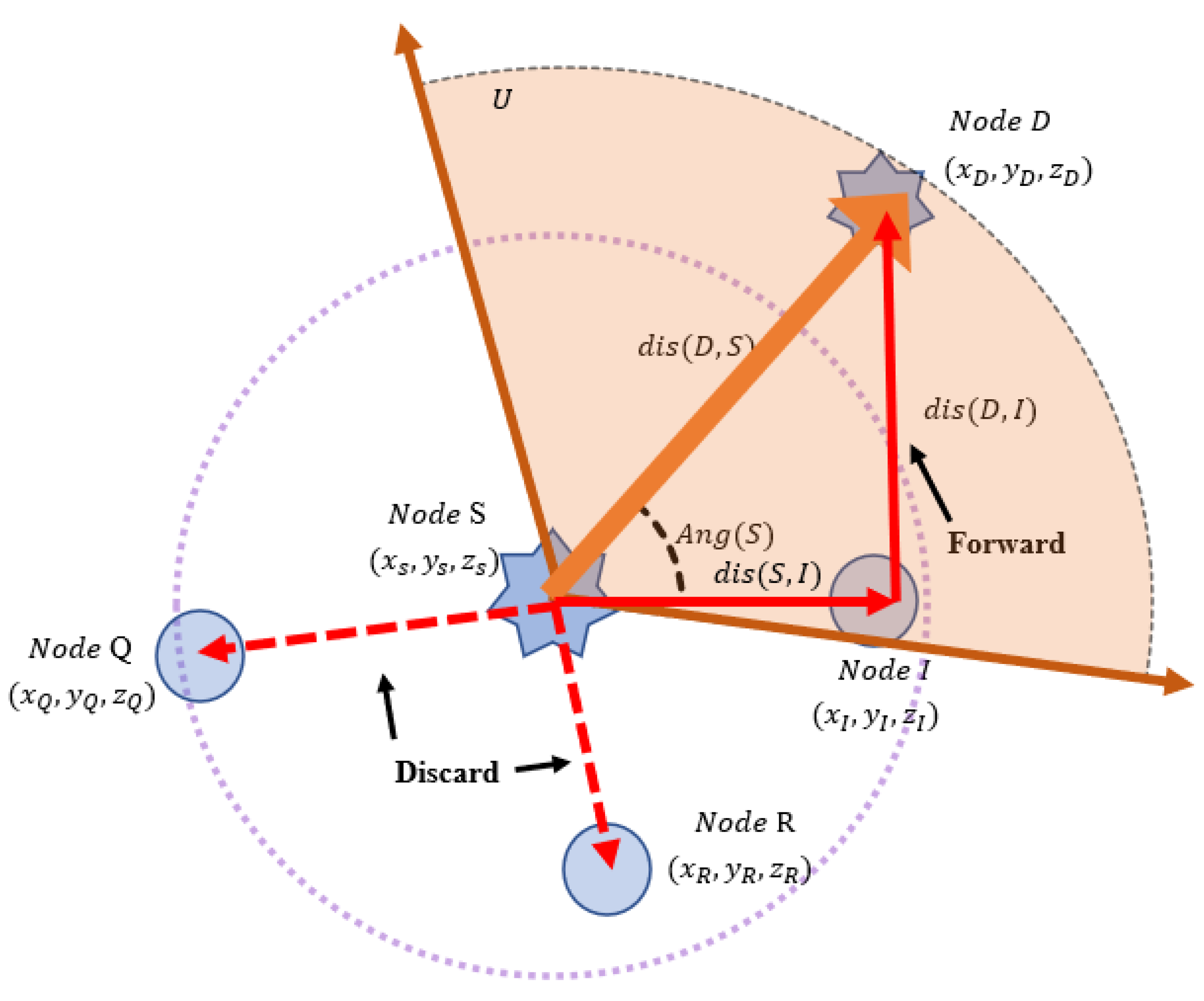
In this subsection, we introduce the GLAN algorithm, which can deliver data in an optimal direction even when broadcasting. When a data transmission request reaches the UAV server, the locations of S and D are confirmed in a simulation. Figure 4 presents the map of the GLAN system.
Figure 4.
Map of GLAN system.
We consider a situation wherein data need to be passed from node S to node D. If the final destination of transmission is not within the T of the transmitted UAV, a forwarding process is required. The distance from S to D can be obtained through an equation that can be expressed as
where a is S and b is D. According to Equation (1), since node D is outside the T of node S, forwarding is required to transmit the data successfully. Therefore, S requests forwarding to nodes within the T through broadcasting. The intermediate node checks whether its position is in the FR. The distances between S, D, and I can be obtained through Equation (1), and the cos value of Ang(S) can be obtained through Equation (2), which can be expressed as
where a is node S, b is node I, and c is node D for the situation in Figure 4. Ang(S) can be obtained through Equation (3), which can be expressed as
where a equals Ang(S). When Ang(S) is obtained through Equation (3), it determines whether to forward or discard the data by comparison with U. Because Ang(s) has a lower value than U, the data are forwarded to node D. It can be seen that node I is in the FR, while nodes Q and R are not.
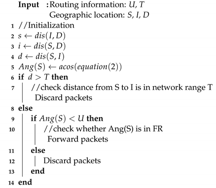
The process of the GLAN algorithm is expressed in Algorithm 1. Firstly, the algorithm calculates the distance from node S to I to check whether node I is in the network range of node S. If d has a larger value than T, it means that node I is out of range of Node S, so we discard the packets. Otherwise, the algorithm compares U and Ang(S) to determine whether node I is in the FR. If node I is in the FR, the data are forwarded to node D. This algorithm is repeated until the packet arrives at its destination.
| Algorithm 1: GLAN algorithm procedure |
 |
This proposed system reduces the number of links that generate the network load, which is a problem when broadcasting data through the GLAN algorithm, and delivers data through an optimized path. The overhead is reduced by allowing the same cluster to send and receive data by connecting to the IP through location information, without the need for a routing table. In addition, the reliability of broadcast data that anyone can access is secured through the UAV swarm ad hoc key.
4. Adaptive GLAN Using Reinforcement Learning
In this section, we present an adaptive GLAN (AGLAN) protocol for UAV networks. We aim to reduce the memory and computational requirements by applying RL to the GLAN algorithm. Learning is carried out to converge the angle of the FR determined by the GLAN algorithm to an optimal angle using attention-enabled deep Q-networks (). A customized RL algorithm, , learns quickly and accurately by combining the attention mechanism and the existing DQN.
RL is an algorithm that finds a goal by learning through mistakes and rewards. The objective is to learn the optimal behavior or policy. Since it is a UAV environment where missions must be performed quickly with little data, a value-based algorithm is more suitable than a policy-based algorithm. Furthermore, by applying the attention mechanism to DQN, we speed up the learning rate of DQN. In addition, can set target policies so that the UAV network can be optimized, establish optimal policies through sufficient exploration, and improve the learning accuracy by reducing correlations between states using experience replay.
We obtain location information and set the routing address of each node. By associating the IP address with the geographic location, the FR is determined. Thus, in the routing process, the unnecessary waste of resources can be prevented. However, this FR is crucial. To obtainan optimal FR, several aspects should be considered, besides the positions of UAVs.
4.1. AGLAN Environment Setting
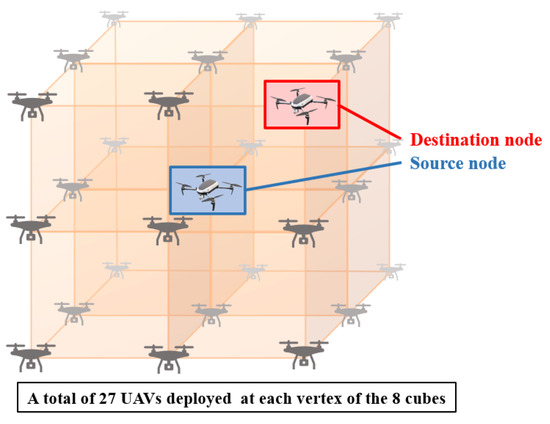
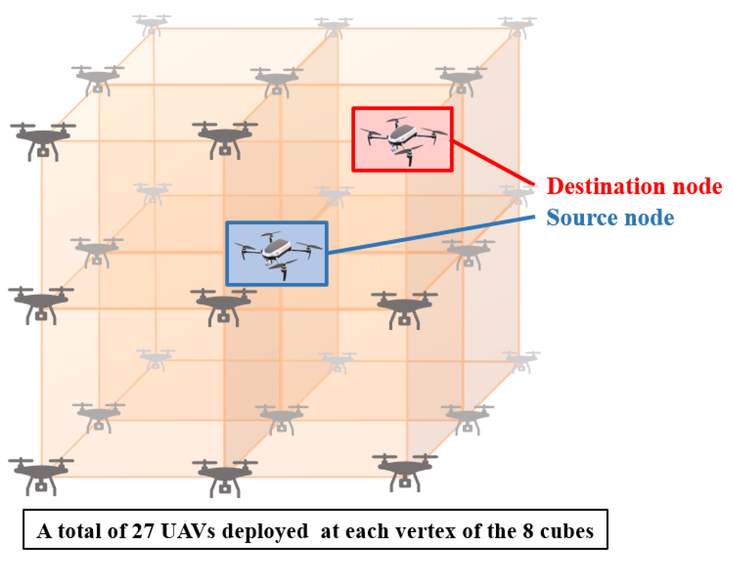
Since the UAVs are clustered, it is necessary that they maintain a specific topology. The topology used in this system is in the form of a 2 × 2 cube, as in Figure 5. The UAV swarm topology can be set to a sphere, pyramid, etc. In addition, there is no difficulty in applying various cluster topologies that are different from the topology discussed in this paper, as long as the location information can be easily obtained. We proceeded in the form of a cube topology that is easy to understand spatially. In Figure 5, the blue UAV is the source and the red UAV is the destination, and the rest of the UAVs are intermediate nodes. We applied the simulation environment containing geographic location information and data transfer information as an RL environment. We considered UAV mobility that varied according to the environment by adding mobility errors within a certain range defined for each UAV model to the current location. AGLAN considers possible mobility errors for each UAV and blocks possible variables by reflecting the information in advance to the RL environment. In each episode, all UAVs in the swarm were set to randomly change positions within the mobility error range at their respective locations.
Figure 5.
2 × 2 cube topology setting in RL environment.
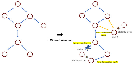
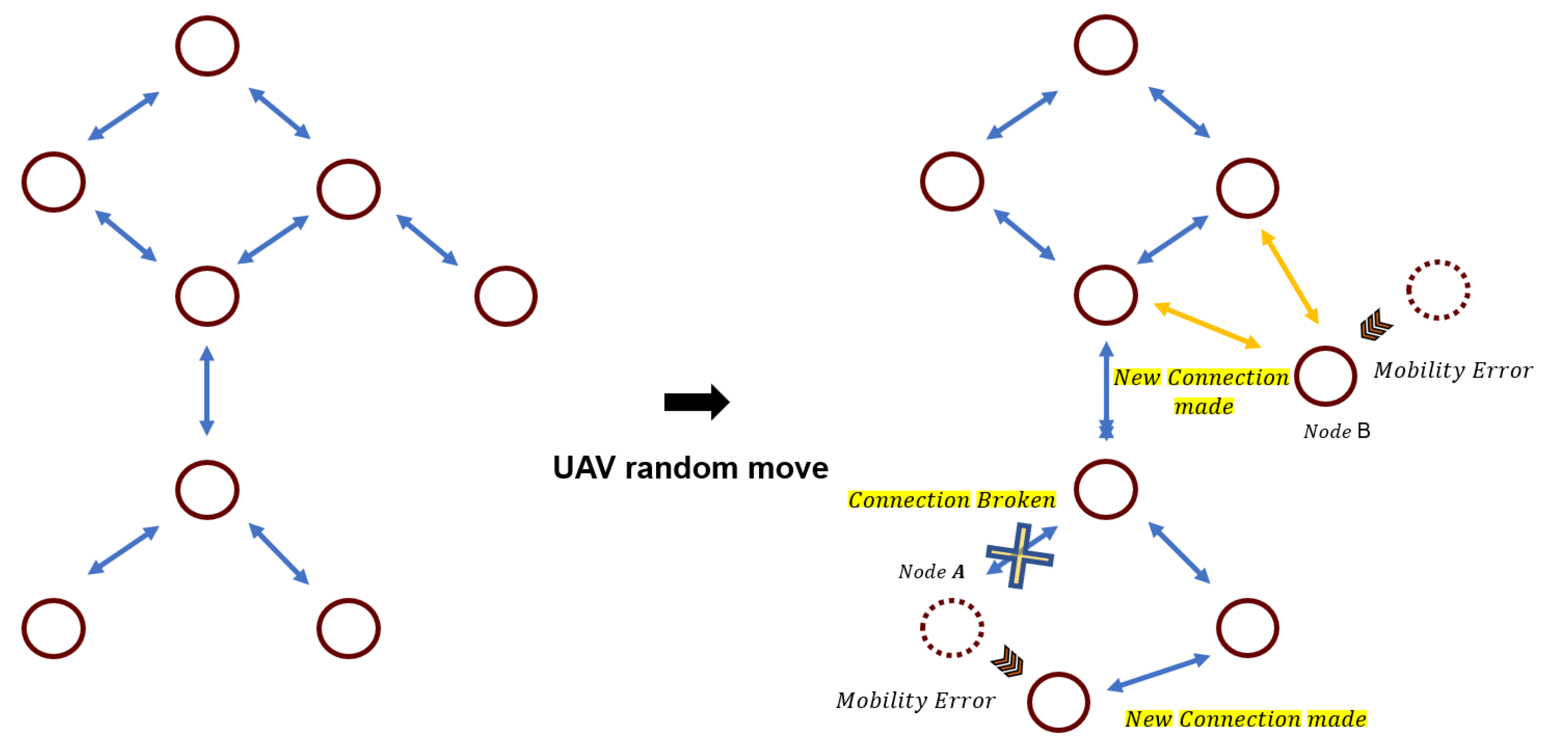
If a mobility error is applied in the environment, as shown in Figure 6, there are a couple of network changes, such as disconnecting links or creating new network links. For example, with node A, it can move out of the network range of the previously connected node, disconnect the existing connection, and form a new network with another node that is within the coverage range, or a new link can be created, such as node B. In this system, the situation in which the mobility error occurs at a fixed location is implemented, and then the best result is found through learning.
Figure 6.
Mobility error considered.
4.2. Reinforcement Learning in AGLAN with
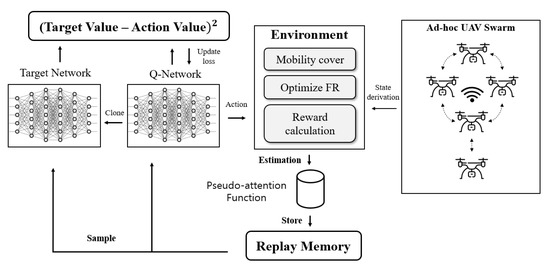
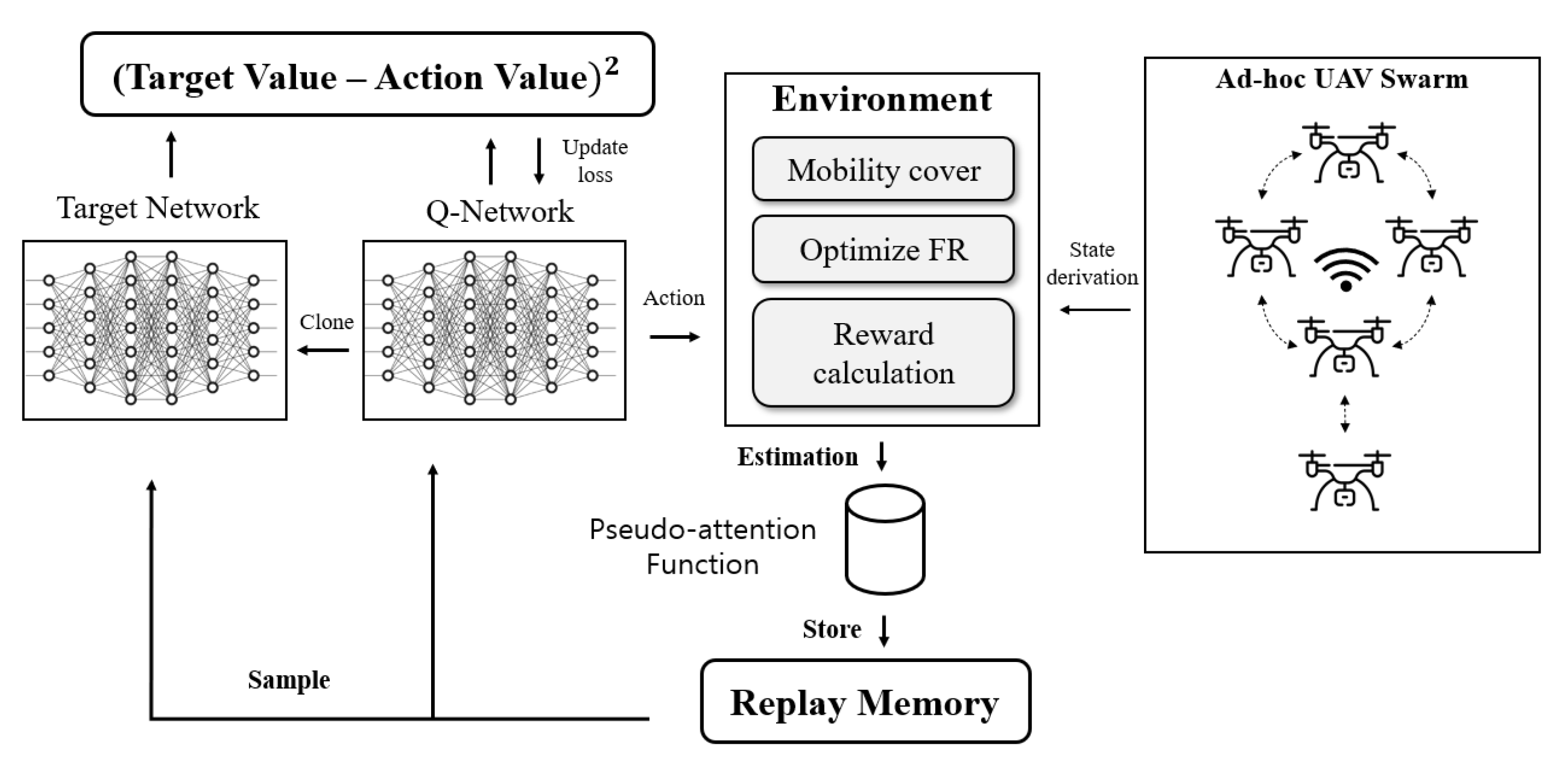
Figure 7 depicts the structure of in our system. When the UAV swarm delivers geographic location and data communication information to the server, the server creates a simulation environment based on the information and covers the expected UAV mobility by giving changes less than the mobility size to all UAVs at every episode. The proposed system provides an optimized zone over the existing forwarding region through learning. In , overestimation problems often occur when the action value becomes excessively large during learning. To prevent this, in this paper, an estimation function called the pseudo-attention layer is added to give a relative value to each action through the evaluation of the action in the current state. This pseudo-attention serves to direct the routing closer to the destination. Even considering random mobility from the source UAV to the destination UAV, we reduce the reward weight for actions that overload the network. Through this process, we can learn at a relatively fast speed by reducing the learning that was overestimated.
Figure 7.
target network structure of AGLAN system.
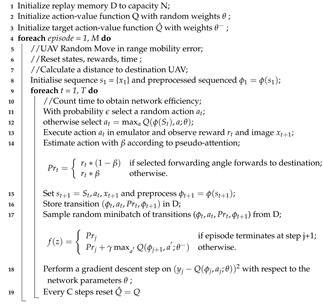
Algorithm 2 is the integrated pseudocode of including experience replay and the target network. A buffer called replay memory is created to store samples generated at each step, and randomly extracted samples are used for Q-update learning. By using experience replay, data efficiency can be increased as one sample can be used for multiple model updates, and the update variance can be reduced by removing sample correlation by randomly extracting data. In addition, the behavior policy is averaged to suppress the oscillation and divergence of parameters during learning, increasing the learning stability. It replicates the existing Q-network identically to create a dual structure of the main Q-network and target network. By having a dual network structure through the target network, learning instability due to the moving target value is improved. The Q-network is used to obtain the action value Q, which is the result value, using the state and action, and the parameters are updated at every step. The target network is used to obtain a target value, which is the reference value for an update. Since the target value network is also parameterized with , as with the main Q-network, it is not updated every time, but the model is updated in the desired direction in synchronization with the main network at every c step.
| Algorithm 2: AGLAN learning with attention deep Q-network |
 |
4.3. System Environment
An agent performs learning and continuously interacts with the environment, so the environment must be configured well. In this system, the FR angle changes as the episode progresses and determines the network coverage range. In the proposed system, it is initially planned to train using 100 episodes of 100-step functions. This subsection provides a detailed description of the state, action, and reward.
4.3.1. State Space
The states used for learning are as follows:
The state consists of the FR angle and time that best represent the AGLAN network. First, the FR angle is the angle of the receiving zone. As the FR angle increases, the FR range widens, increasing the possibility that data will arrive at its destination reliably. Conversely, if it is smaller, the number of nodes to be covered is reduced and the network load can be reduced. Second, time refers to the time taken to travel from the starting point to the destination, or the time for which it does not arrive. As the FR range narrows, the arrival time to the destination is likely to be shortened and communication failures can be checked quickly, while the wider the FR range, the more stable it is. Since these two elements can represent various characteristics of the AGLAN network, they are suitable as components of the state for the learning model.
4.3.2. Action Space
The action used for learning is as follows:
The proposed system uses AGLAN’s FR angle change as an action for learning. It does not cover all 360 degrees randomly and changes the FR angle within a certain range from the value set as default in AGLAN. As the FR angle changes, both states are affected, and, as a result, the action is repeated, leading to a change in the next state, enabling the smooth learning of the entire system.
4.3.3. Reward
The rewards used for learning are as follows:
Each episode learns according to the changed position due to the mobility characteristics of the UAV. First, if the data successfully arrive at their destination, a large reward is given. Conversely, if they do not arrive, it is determined that the learned reward value is not suitable for learning and a negative reward is given accordingly. In addition, negative compensation is given when a network link between UAVs is created to reduce the network load. AGLAN’s reward is calculated as the weighted product of the hyperparameter and the time component.
5. Performance Evaluation
We designed the AGLAN system and constructed an environment that could perform real tasks. In this section, we present details of our implementation and a series of experiments to verify its operations and evaluate its performance.
5.1. Implementation
The experiment was conducted in the Ubuntu 20.04 environment using Odroid, a single-board computer that can be mounted on a real drone. A network interface controller (NIC) was installed on Odroid to communicate, and the GPS address was obtained through MAVROS. The obtained GPS information was reflected on the private A-class IP address and connected through an ad hoc network to form a UAV swarm network.
The UAV server used Python to configure the simulation environment, and the location information of the UAVs was updated when they arrived at the server [33]. It was assumed that the UAV swarm followed a constant formation topology and a 2 × 2 cube topology was used [34]. After the positions of all UAVs in the swarm were updated on the simulation, when a data transmission request arrived from one UAV, the source node and destination node were set, and the appropriate FR angle was set as the default at the current position. Learning was started to optimize the fixed FR angle according to the situation.
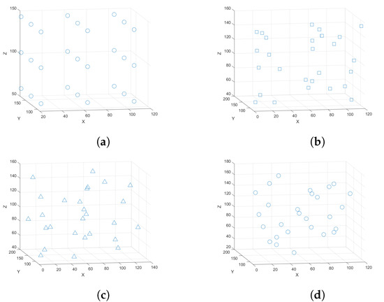
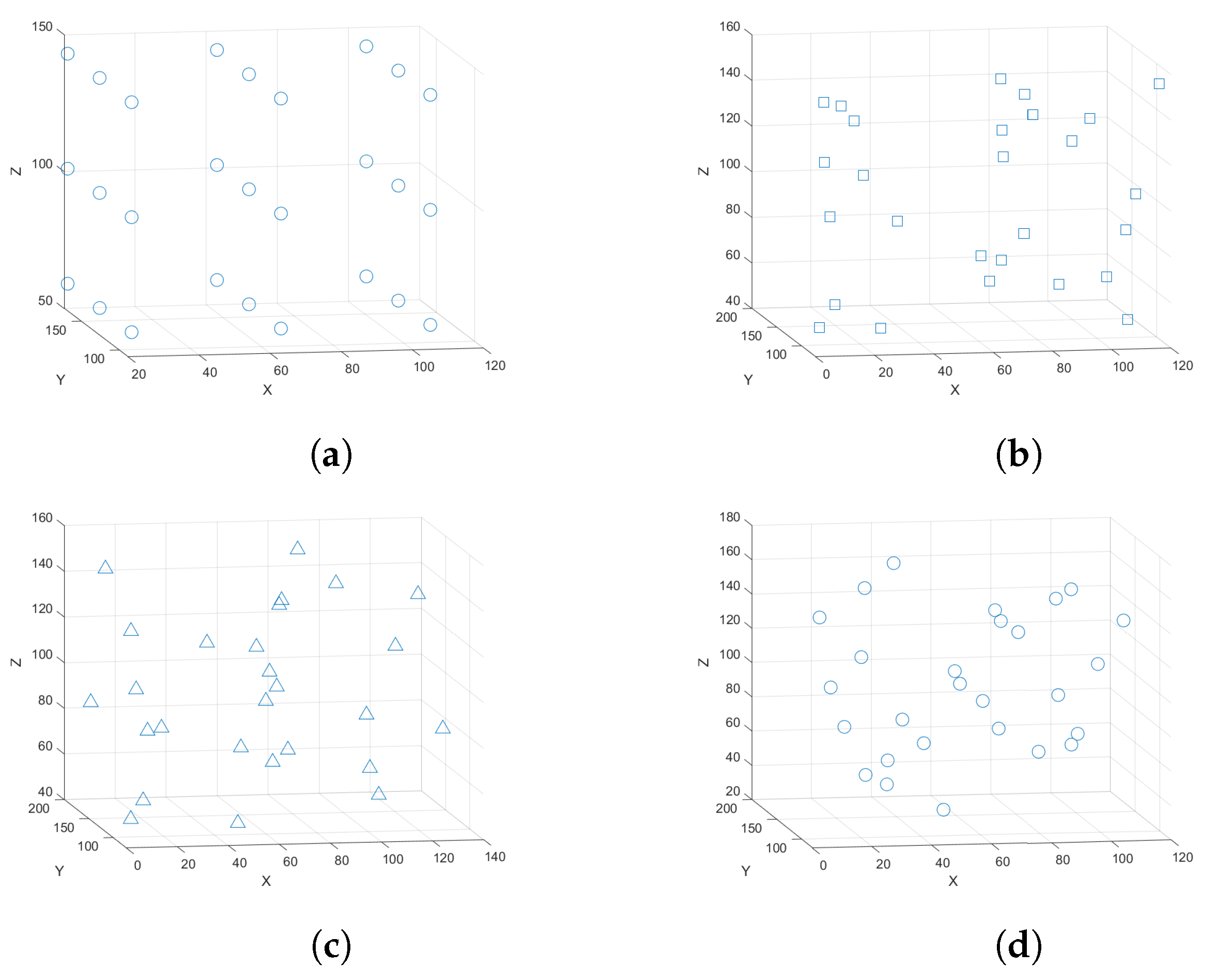
Prior to full-scale learning, the location was randomly changed within the mobility error range of the UAV for each episode to form a network suitable for the UAV network. Figure 8a is an example in which 27 UAVs form a 2 × 2 cube topology and the network range is set to 42 m. Figure 8b–d are examples with the mobility error set to 13 m.
Figure 8.
(a) 2 × 2 cube topology, (b) 2 × 2 cube topology considering UAV mobility for episode 1, (c) 2 × 2 cube topology considering UAV mobility for episode 10, (d) 2 × 2 cube topology considering UAV mobility for episode 50.
5.2. Reinforcement Learning Results
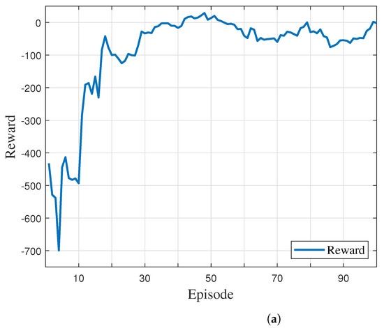
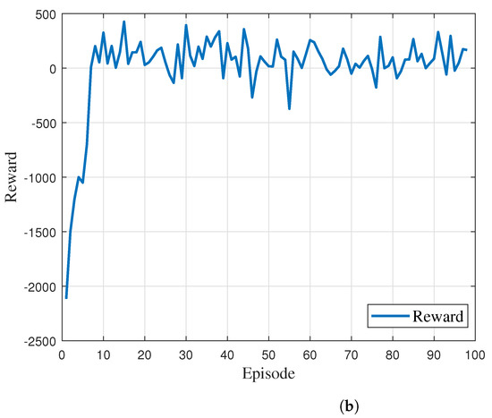
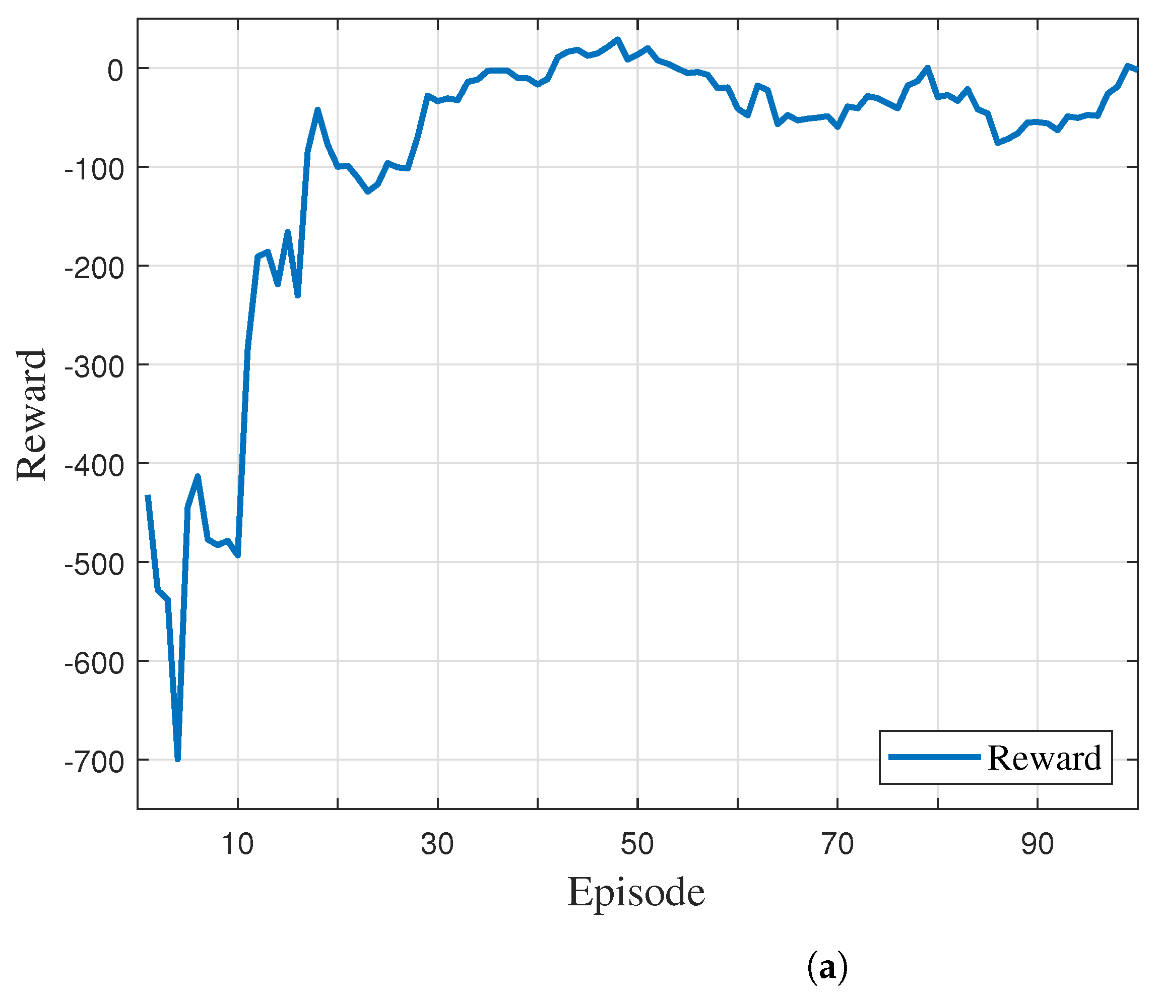
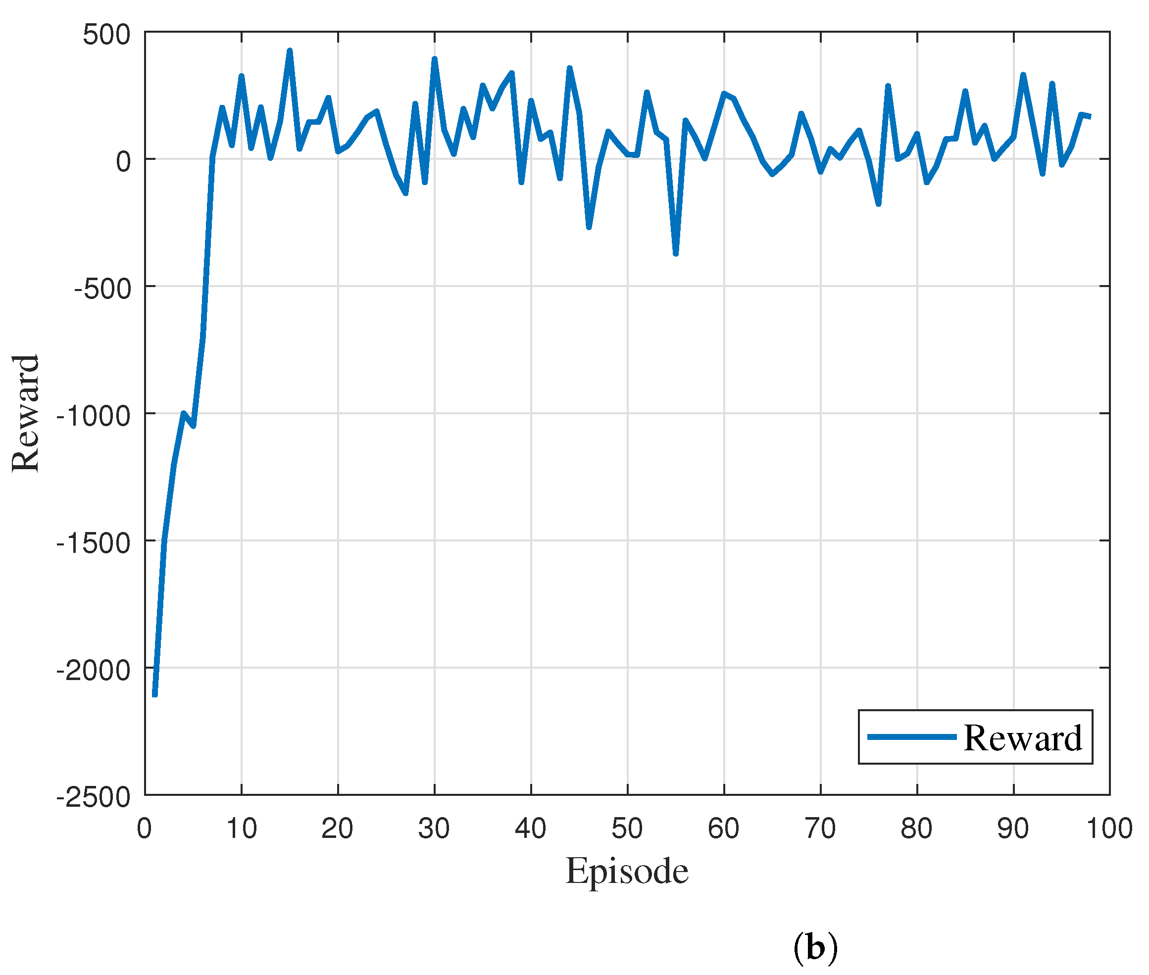
AGLAN considers the mobility error situation and secures the stability of data delivery through broadcasting and optimizes it through learning. In the UAV swarm environment where the UAV mobility error is applied to the cube topology, 100 steps are executed per episode. At each step, an action is randomly selected and we learn the FR angle previously set as the default. The optimal UAV routing can be achieved by calculating the reward through the network change that occurs as the FR changes. Figure 9 shows the reward graph when learning is progressing. At first, the reward is very low, but, as the episode progresses, it can be seen that it is gradually optimized. In addition, the learning speed is improved when pseudo-attention is applied to . It can be seen that Figure 9b converges faster than Figure 9a.
Figure 9.
(a) episodic reward results; (b) with pseudo-attention episodic reward results.
5.3. Network Efficiency Experiment
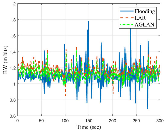
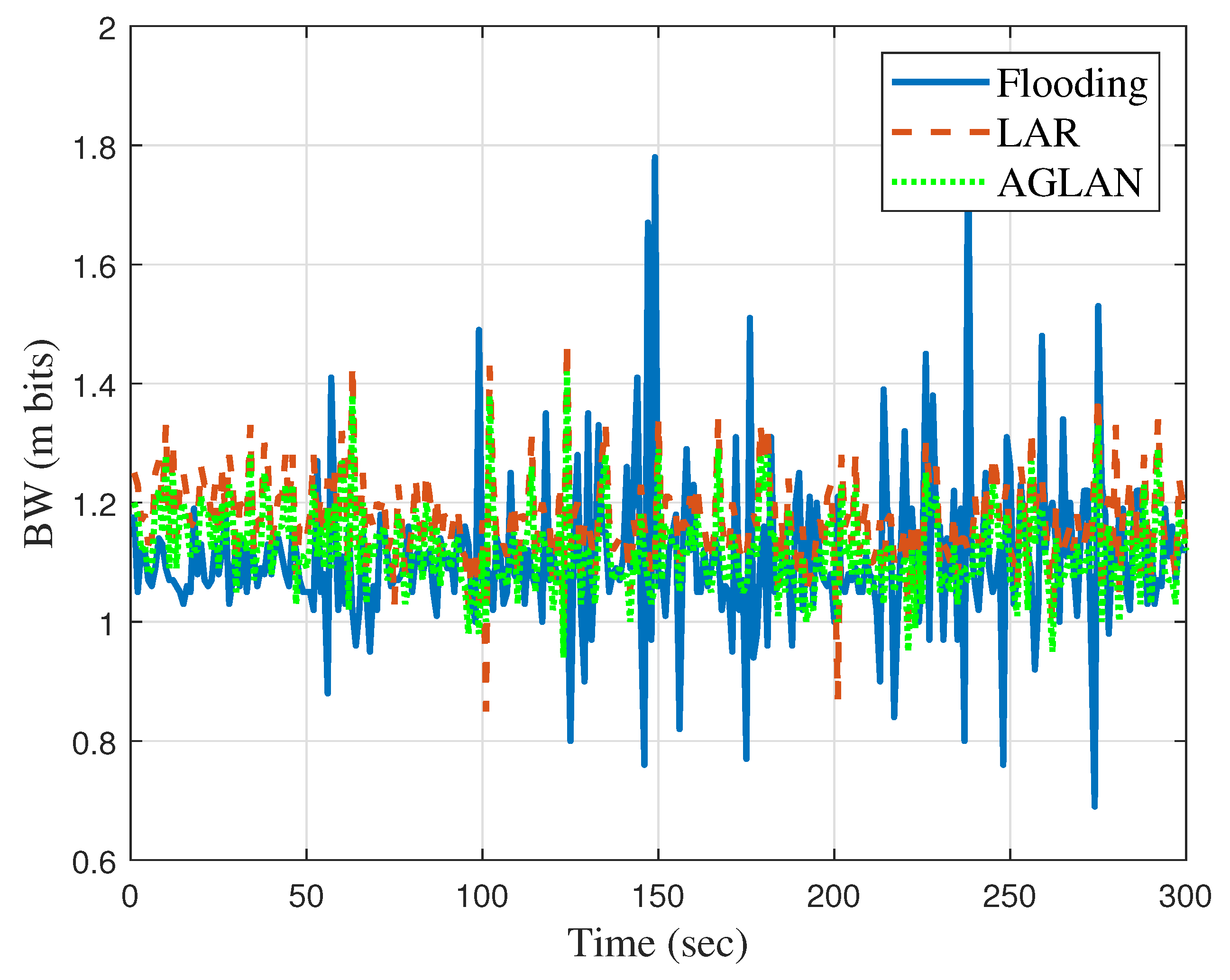
When the is completed, the server delivers the learning information to all UAVs in the swarm in order to apply the learned FR angle to actual routing communication. Each UAV chooses whether to forward or discard by adding routing rules that check whether it belongs to the FR when it receives the broadcast data. We compared the network bandwidth when each routing algorithm was used in all UAVs in the swarm. Figure 10 shows that AGLAN maintains a more stable network BW than LAR.
Figure 10.
Comparison of BW among flooding, LAR, and AGLAN.
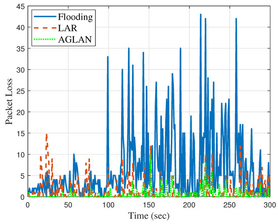
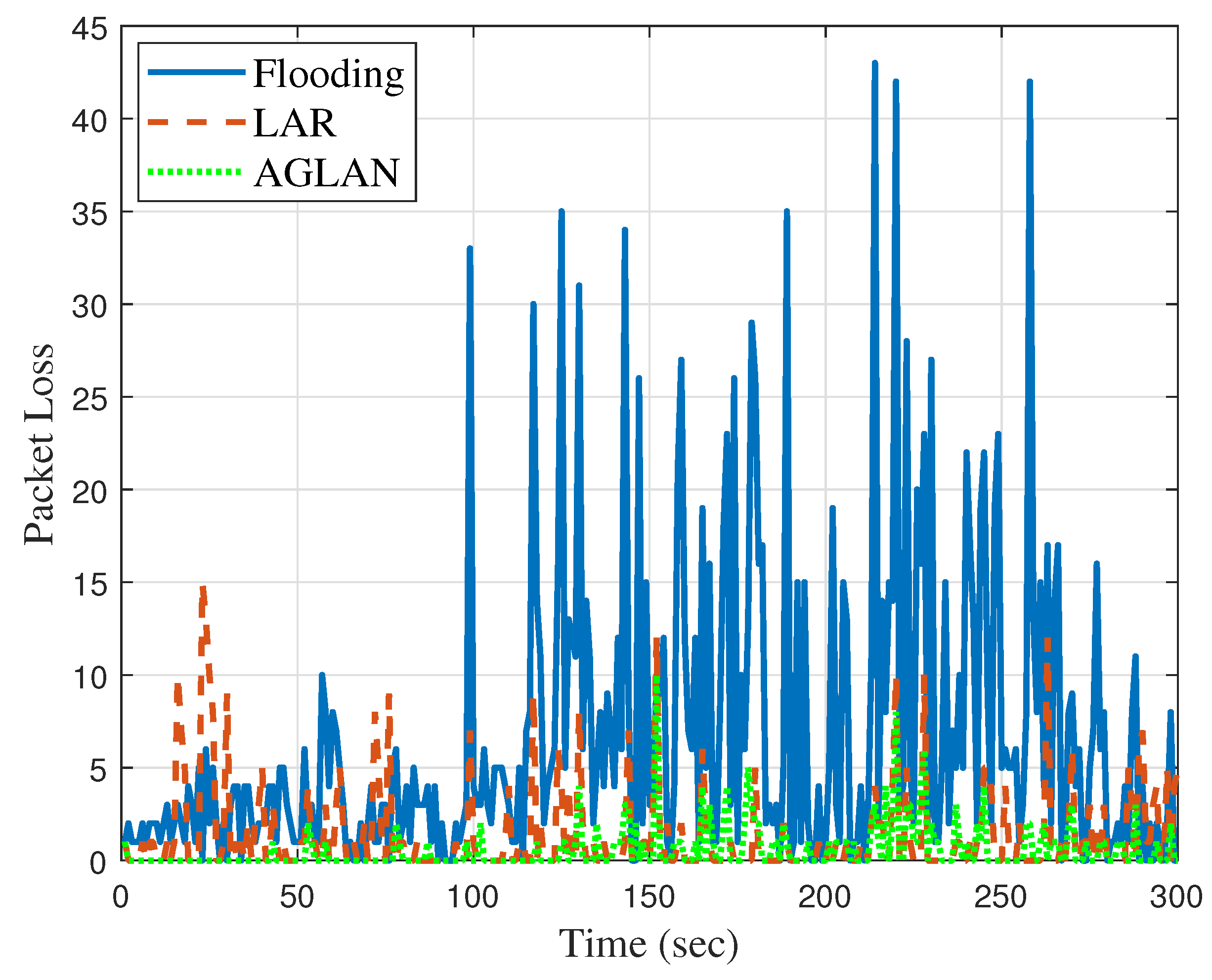
Figure 11 is a graph depicting the packet loss that occurs when flooding, LAR, and AGLAN are executed. Datagrams lost for 300 s were measured. Flooding resulted in 1995 packet losses, 7.4% of a total of 26,753 packets, and LAR caused 408 packet losses, 1.5% of 26,158 packets. In contrast, AGLAN only incurred 169 packet losses, which is 0.63% of 26,753 packets. It can be seen that AGLAN is 6.77% better than flooding and 0.87% better than LAR.
Figure 11.
Comparison of packet loss among flooding, LAR, and AGLAN.
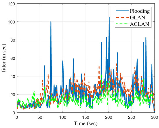
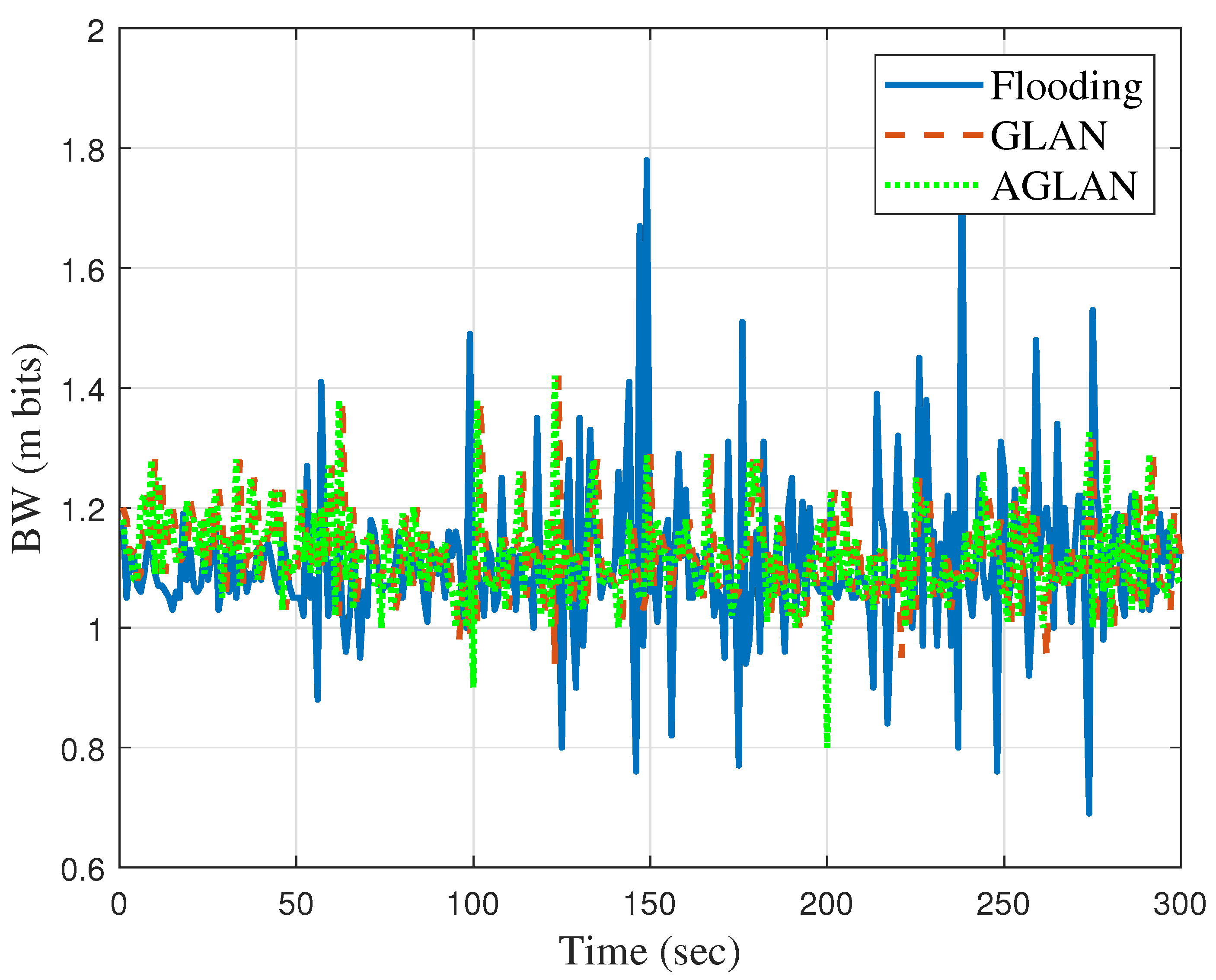
Figure 12 is a graph comparing the jitter of the GLAN system, the system with RL added to GLAN, and flooding, an existing routing algorithm. As we can see in the graph, GLAN applies the default FR angle according to the current position, so, depending on the situation, it may be worse than flooding or show similar values to the learned GLAN. The trained GLAN with RL always gives better results than flooding. AGLAN has an average jitter value that is 61% lower than that of flooding.
Figure 12.
Comparison of jitter among flooding, GLAN, and AGLAN.
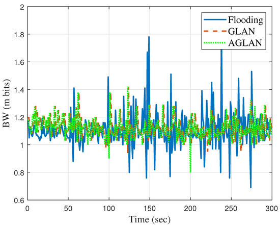
Figure 13 is a bandwidth comparison graph. It can be seen that the bandwidth performance of GLAN is almost equal to or greater than that of flooding. The average bandwidth shows that AGLAN is 9% better than flooding.
Figure 13.
Comparison of bandwidth among flooding, GLAN, and AGLAN.
6. Conclusions
As UAV technology develops gradually, it is necessary to optimize the ever-changing UAV networks. In a UAV network, data are transmitted and received based on broadcasting or ad hoc routing. Although broadcasting can deliver data reliably to the destination, the network load is high. In comparison, ad hoc routing wastes the network bandwidth and introduces network delays in transmitting the routing information needed to establish an effective communication path. Based on these observations, we proposed a method of optimizing data transmission through UAV networks based on RL to exploit the advantages of the two methods. In the proposed system, we utilized geographic location information in a situation where the location changed due to the movement of the UAV and also devised a new DQN called to optimize the forwarding area.
We have several directions for future work. The proposed system can be further improved by using more learning algorithms besides aDQN. Instead of flooding, it may be possible to derive a more advanced routing system by identifying how different routing algorithms are used in the UAV environment and configuring optimization plans. Alternatively, we can increase the accuracy of existing routing algorithms by considering the mobility errors used in AGLAN. In addition, we plan to build an optimized routing path by utilizing the GLAN algorithm in a communication environment where network information is not accurate or does not arrive on time. Regarding security issues, we wish to solve the problem of allowing only data with a separate network key to be transmitted and received.
Author Contributions
Conceptualization, C.P. and H.K.; methodology, C.P.; software, C.P.; validation, C.P. and H.K.; formal analysis, C.P.; resources, H.K.; data curation, H.K.; writing—original draft preparation, C.P., S.L., H.J. and H.K.; writing—review and editing, H.K.; visualization, C.P.; supervision, H.K.; project administration, H.K.; funding acquisition, H.K. All authors have read and agreed to the published version of the manuscript.
Funding
This work was supported by the Human Resources Program in Energy Technology of the Korea Institute of Energy Technology Evaluation and Planning (KETEP) and the Ministry of Trade, Industry & Energy (MOTIE) of the Republic of Korea (No. 20204010600220) and the National Research Foundation of Korea funded by the Korean Government (grant 2020R1A2C1012389).
Data Availability Statement
Not applicable.
Conflicts of Interest
The authors declare no conflict of interest. Furthermore, the funders had no role in the design of the study; in the collection, analyses or interpretation of data; in the writing of the manuscript; or in the decision to publish the results.
Abbreviations
The following abbreviations are used in this manuscript:
| UAV | Unmanned aerial vehicle |
| FR | Forwarding region |
| RL | Reinforcement learning |
References
- Katila, C.J.; Okolo, B.; Buratti, C.; Verdone, R.; Caire, G. UAV-to-Ground Multi-Hop Communication Using Backpressure and FlashLinQ-Based Algorithms. In Proceedings of the 2018 IEEE 29th Annual International Symposium on Personal, Indoor and Mobile Radio Communications (PIMRC), Bologna, Italy, 9–12 September 2018; pp. 1179–1184. [Google Scholar] [CrossRef] [Scilit]
- Chen, W.; Liu, J.; Guo, H.; Kato, N. Toward robust and intelligent drone swarm: Challenges and future directions. IEEE Netw. 2020, 34, 278–283. [Google Scholar] [CrossRef] [Scilit]
- Arafat, M.Y.; Habib, M.A.; Moh, S. Routing protocols for UAV-aided wireless sensor networks. Appl. Sci. 2020, 10, 4077. [Google Scholar] [CrossRef] [Scilit]
- Ebrahimi, D.; Sharafeddine, S.; Ho, P.H.; Assi, C. UAV-aided projection-based compressive data gathering in wireless sensor networks. IEEE Internet Things J. 2018, 6, 1893–1905. [Google Scholar] [CrossRef] [Scilit]
- Sharma, V.; Kumar, R. A cooperative network framework for multi-UAV guided ground ad hoc networks. J. Intell. Robot. Syst. 2015, 77, 629–652. [Google Scholar] [CrossRef] [Scilit]
- Park, S.; Kim, K.; Kim, H.; Kim, H. Formation control algorithm of multi-UAV-based network infrastructure. Appl. Sci. 2018, 8, 1740. [Google Scholar] [CrossRef] [Scilit]
- Ghosekar, P.; Katkar, G.; Ghorpade, P. Mobile ad hoc networking: Imperatives and challenges. Ijca Spec. Issue Manets 2010, 3, 153–158. [Google Scholar]
- Blum, J.J.; Eskandarian, A.; Hoffman, L.J. Challenges of intervehicle ad hoc networks. IEEE Trans. Intell. Transp. Syst. 2004, 5, 347–351. [Google Scholar] [CrossRef] [Scilit]
- Lin, L.; Sun, Q.; Wang, S.; Yang, F. A geographic mobility prediction routing protocol for ad hoc UAV network. In Proceedings of the 2012 IEEE Globecom Workshops, Anaheim, CA, USA, 3–7 December 2012; pp. 1597–1602. [Google Scholar]
- Xu, Y.; Heidemann, J.; Estrin, D. Geography-informed energy conservation for ad hoc routing. In Proceedings of the Proceedings of the 7th Annual International Conference on Mobile Computing and Networking, New York, NY, USA, 16–21 July 2001; pp. 70–84. [Google Scholar]
- Lee, S.; Yoo, S.; Lee, J.Y.; Park, S.; Kim, H. Drone Positioning System Using UWB Sensing and Out-of-Band Control. IEEE Sensors J. 2021, 22, 5329–5343. [Google Scholar] [CrossRef] [Scilit]
- Oubbati, O.S.; Lakas, A.; Zhou, F.; Güneş, M.; Yagoubi, M.B. A survey on position-based routing protocols for Flying Ad hoc Networks (FANETs). Veh. Commun. 2017, 10, 29–56. [Google Scholar] [CrossRef] [Scilit]
- Blazevic, L.; Le Boudec, J.Y.; Giordano, S. A location-based routing method for mobile ad hoc networks. IEEE Trans. Mob. Comput. 2005, 4, 97–110. [Google Scholar] [CrossRef] [Scilit]
- Bose, P.; Morin, P.; Stojmenović, I.; Urrutia, J. Routing with guaranteed delivery in ad hoc wireless networks. In Proceedings of the Proceedings of the 3rd International Workshop on Discrete Algorithms and Methods for Mobile Computing and Communications, Seattle, WA, USA, 20 August 1999; pp. 48–55. [Google Scholar]
- Sahingoz, O.K. Mobile networking with UAVs: Opportunities and challenges. In Proceedings of the 2013 International Conference on Unmanned Aircraft Systems (ICUAS), Atlanta, GA, USA, 28–31 May 2013; pp. 933–941. [Google Scholar]
- Ko, Y.B.; Vaidya, N. Location-Aided Routing (LAR) in mobile ad hoc networks. In Proceedings of the 4th annual ACM/IEEE International Conference on Mobile Computing and Networking, Dallas, TX, USA, 25–30 October 1998; Volume 6, pp. 307–321. [Google Scholar] [CrossRef] [Scilit]
- Karp, B.; Kung, H.T. GPSR: Greedy perimeter stateless routing for wireless networks. In Proceedings of the 6th Annual International Conference on Mobile Computing and Networking, Boston, MA, USA, 6–11 August 2000; pp. 243–254. [Google Scholar]
- Agrawal, R.; Faujdar, N.; Romero, C.A.T.; Sharma, O.; Abdulsahib, G.M.; Khalaf, O.I.; Mansoor, R.F.; Ghoneim, O.A. Classification and comparison of ad hoc networks: A review. Egypt. Inform. J. 2022, 24, 1–25. [Google Scholar] [CrossRef] [Scilit]
- Bouachir, O.; Abrassart, A.; Garcia, F.; Larrieu, N. A Mobility Model For UAV Ad hoc Network. In Proceedings of the ICUAS 2014, International Conference on Unmanned Aircraft Systems, Orlando, FL, USA, 27–30 May 2014; pp. 383–388. [Google Scholar]
- Jacquet, P.; Muhlethaler, P.; Clausen, T.; Laouiti, A.; Qayyum, A.; Viennot, L. Optimized link state routing protocol for ad hoc networks. In Proceedings of the IEEE International Multi Topic Conference, 2001, IEEE INMIC 2001, Technology for the 21st Century, Lahore, Pakistan, 30 December 2001; pp. 62–68. [Google Scholar] [CrossRef] [Scilit]
- Perkins, C.; Royer, E. Ad-hoc on-demand distance vector routing. In Proceedings of the WMCSA’99, Second IEEE Workshop on Mobile Computing Systems and Applications, New Orleans, LA, USA, 25–26 February 1999; pp. 90–100. [Google Scholar] [CrossRef] [Scilit]
- Xie, J.; Talpade, R.R.; McAuley, A.; Liu, M. AMRoute: Ad hoc multicast routing protocol. Mob. Netw. Appl. 2002, 7, 429–439. [Google Scholar] [CrossRef] [Scilit]
- Wu, C.W.; Tay, Y. AMRIS: A multicast protocol for ad hoc wireless networks. In Proceedings of the MILCOM 1999, IEEE Military Communications, Conference Proceedings (Cat. No. 99CH36341), Atlantic City, NJ, USA, 31 October–3 November 1999; Volume 1, pp. 25–29. [Google Scholar]
- Lee, S.J.; Gerla, M.; Chiang, C.C. On-demand multicast routing protocol. In Proceedings of the WCNC. 1999 IEEE Wireless Communications and Networking Conference (Cat. No. 99TH8466), New Orleans, LA, USA, 21–24 September 1999; Volume 3, pp. 1298–1302. [Google Scholar]
- Garcia-Luna-Aceves, J.J.; Madruga, E.L. The core-assisted mesh protocol. IEEE J. Sel. Areas Commun. 1999, 17, 1380–1394. [Google Scholar] [CrossRef] [Scilit]
- Corson, S.; Macker, J. Mobile Ad Hoc Networking (MANET): Routing Protocol Performance Issues and Evaluation Considerations; Technical Report; ACM: New York, NY, USA, 1999. [Google Scholar]
- Bekmezci, I.; Sahingoz, O.K.; Temel, Ş. Flying ad-hoc networks (FANETs): A survey. Hoc Netw. 2013, 11, 1254–1270. [Google Scholar] [CrossRef] [Scilit]
- Kaelbling, L.P.; Littman, M.L.; Moore, A.W. Reinforcement learning: A survey. J. Artif. Intell. Res. 1996, 4, 237–285. [Google Scholar] [CrossRef] [Scilit]
- Arulkumaran, K.; Deisenroth, M.P.; Brundage, M.; Bharath, A.A. Deep reinforcement learning: A brief survey. IEEE Signal Process. Mag. 2017, 34, 26–38. [Google Scholar] [CrossRef] [Scilit]
- Boyan, J.; Littman, M. Packet Routing in Dynamically Changing Networks: A Reinforcement Learning Approach. Adv. Neural Inf. Process. Syst. 1999, 6, 671–678. [Google Scholar]
- Santhi, G.; Nachiappan, A.; Ibrahime, M.Z.; Raghunadhane, R.; Favas, M.K. Q-learning based adaptive QoS routing protocol for MANETs. In Proceedings of the 2011 International Conference on Recent Trends in Information Technology (ICRTIT), Chennai, India, 3–5 June 2011; pp. 1233–1238. [Google Scholar] [CrossRef] [Scilit]
- Zheng, Z.; Sangaiah, A.K.; Wang, T. Adaptive Communication Protocols in Flying Ad Hoc Network. IEEE Commun. Mag. 2018, 56, 136–142. [Google Scholar] [CrossRef] [Scilit]
- Python. Available online: https://www.python.org/ (accessed on 20 February 1991).
- Yoo, T.; Lee, S.; Yoo, K.; Kim, H. Reinforcement Learning Based Topology Control for UAV Networks. Sensors 2023, 23, 921. [Google Scholar] [CrossRef] [Scilit] [PubMed]


Disclaimer/Publisher’s Note: The statements, opinions and data contained in all publications are solely those of the individual author(s) and contributor(s) and not of MDPI and/or the editor(s). MDPI and/or the editor(s) disclaim responsibility for any injury to people or property resulting from any ideas, methods, instructions or products referred to in the content. |
© 2023 by the authors. Licensee MDPI, Basel, Switzerland. This article is an open access article distributed under the terms and conditions of the Creative Commons Attribution (CC BY) license (https://creativecommons.org/licenses/by/4.0/).