Article

QuickNav: An Effective Collision Avoidance and Path-Planning Algorithm for UAS

by
Dipraj Debnath
1,2,
Ahmad Faizul Hawary
3,*,
Muhammad Iftishah Ramdan
4,
Fernando Vanegas Alvarez
1,2 and
Felipe Gonzalez
1,2
1
School of Electrical Engineering & Robotics, Queensland University of Technology (QUT), QUT S Block, 2 George Street, Brisbane City, QLD 4000, Australia
2
QUT Centre for Robotics (QCR), Queensland University of Technology (QUT), Level 11, QUT S Block, 2 George Street, Brisbane City, QLD 4000, Australia
3
School of Aerospace Engineering, Universiti Sains Malaysia, Nibong Tebal, Penang 14300, Malaysia
4
School of Mechanical Engineering, Universiti Sains Malaysia, Nibong Tebal, Penang 14300, Malaysia
*
Author to whom correspondence should be addressed.
Drones 2023, 7(11), 678; https://doi.org/10.3390/drones7110678
Submission received: 13 October 2023 / Revised: 8 November 2023 / Accepted: 15 November 2023 / Published: 17 November 2023

Abstract

:
Obstacle avoidance is a desirable capability for Unmanned Aerial Systems (UASs)/drones which prevents crashes and reduces pilot fatigue, particularly when operating in the Beyond Visual Line of Sight (BVLOS). In this paper, we present QuickNav, a solution for obstacle detection and avoidance designed to function as a pre-planned onboard navigation system for UAS flying in a known obstacle-cluttered environment. Our method uses a geometrical approach and a predefined safe perimeter (square area) based on Euclidean Geometry for the estimation of intercepting points, as a simple and efficient way to detect obstacles. The square region is treated as the restricted zone that the UAS must avoid entering, therefore providing a perimeter for manoeuvring and arriving at the next waypoints. The proposed algorithm is developed in a MATLAB environment and can be easily translated into other programming languages. The proposed algorithm is tested in scenarios with increasing levels of complexity, demonstrating that the QuickNav algorithm is able to successfully and efficiently generate a series of avoiding waypoints. Furthermore, QuickNav produces shorter distances as compared to those of the brute force method and is able to solve difficult obstacle avoidance problems in fractions of the time and distance required by the other methods. QuickNav can be used to improve the safety and efficiency of UAV missions and can be applied to the deployment of UAVs for surveillance, search and rescue, and delivery operations.

1. Introduction

The capabilities of Autonomous Unmanned Aircraft Systems (UASs) have significantly advanced in performance and effectiveness in recent years. UAS systems rely on unmanned aerial vehicles (UAVs) and ground control systems (GCSs) equipped with real-time mission control and communication devices to plan and monitor autonomous flights [1]. UAVs are becoming a dependable option in a range of application fields because of the rapid improvements in technologies [2]. This has been enabled by the increasing number of recent deployments of UAVs in a variety of applications [3]. UAVs are being used not only in the military sector, but also in the civil and private sectors [4]. However, in recent years, the use of UAS technology for civil applications has increased due to applications in aerial photography, mapping, target tracking, ecological prediction, etc. [5].
Operation and application requirements at low altitudes, such as monitoring, search and rescue, geological science research, and data collection in isolated places, have recently been influenced by the emergence of small and micro aerial vehicles (SUAVs and MAVs, respectively) [6,7]. These UAVs are employed to achieve several objectives, including the collection of on-demand photographs from low-altitude airspaces. This technology offers extensive assistance in emergency product shipment, border surveillance, emergency rescue operations during disasters, and visual surveillance for crowd safety [8].
The development of autonomous UAVs has become essential to fulfil the increasing needs of the UAS landscape [9]. Modern UAVs aim for increased autonomy and flight stability due to the technical developments, diversity, and complexity of missions [10]. This has led to the development of autonomous UAVs that can be controlled by computers loaded with pre-determined path, detection, and obstacle avoidance algorithms [11,12]. An onboard mission plan consists of path planning algorithms to alter the flight plan when the obstacles have been detected. The automated guidance system will interrupt the flight plan and initiate operations in response to the obstacles, such as when a hazard is identified [13]. The detection and avoidance of obstacles with a high level of accuracy is a challenging problem for autonomous UASs [14].
Over the last decade, there has been a significant increase in research on UAS obstacle detection and avoidance. The development of fast-converging algorithms has been a persistent priority to assure safe and effective navigation, given the dynamic nature of UAS operations. The algorithms utilized for obstacle avoidance control can be classified into two main approaches: optimization-based and rule-based ones [15]. Rule-based algorithms depend on predetermined rules and heuristics to control UAS when they come across obstacles, depending on the expert-derived instructions. These techniques provide effectiveness and immediate applicability, but may encounter difficulties in complex and dynamic situations. On the other hand, optimization-based algorithms approach obstacle avoidance as a problem of finding the best solution, using mathematical methods to calculate the most efficient path, while avoiding the obstacles [16,17].
Sensor technologies are essential in obstacle detection and avoidance systems as they provide real-time data for predetermined routes. Laser range finders (LRF), sound navigation and range finders (SONAR), and cameras are used as sensors in these systems. However, these sensors use intensive computing power and are subject to different environmental uncertainties that necessitate frequent calibration [18].
Several notable approaches and techniques have been proposed in research work to address the difficulties of detecting and avoiding obstacles for UASs. Khan et al. proposed a Flexible Geometric Algorithm (FGA) that solved a possible collision using differential geometry based on the specific location, relative velocities, angular displacements, and collision cones [19]. The probability of a collision occurring is considered in this model using two-dimensional (2D) collision cones. A 2D collision cone is created from the aircraft’s frame and is computed when an obstacle is detected within the protected cone. The key limitation of this model is the assumption that the airplane is flying at a constant speed. Zheng [20] introduced a LIDAR-based approach for obstacle detection and avoidance. In this study, LIDAR is used to scan each point and correction is made to the point cloud via a relationship transformation. The point cloud features obtained via a laser radar are used to derive a clustering method using the relative distance and density. Another approach by Bareiss [21] used an onboard two-dimensional spinning LIDAR system with a one-dimensional rangefinder to detect the obstacles.
Some other researchers such as Yu Wan [22] proposed a collision avoidance system for fixed-wing UAVs based on manoeuvre coordination and planned trajectory prediction. P.S. Krishnan developed a novel Particle Swarm Optimization-based Collision Avoidance algorithm (PSO-CA) for escape manoeuvres away from obstacles. This approach can also be used to discover new waypoints for the dynamic trajectory modification of UAVs [23]. B.K. Patle et al. proposed the Matrix Binary Code with a Genetic Algorithm to optimize static and dynamic environments for path planning and obstacle identification [24]. The authors also introduced the Firefly Algorithm (FA) for mobile robot navigation (MRN) in uncertain environments [25]. The uncertainty is expressed from static to dynamic and changing environments. Wu et al. proposed an obstacle avoidance solution where the unmanned surface vehicle (USV) is travelling along the path provided by the Artificial Potential Field-Ant Colony Optimization (APF-ACO) algorithm [26]. The USV can successfully overcome the current obstacle by using the multi-layer technique.
Hu et al. introduced a path planning technique for static and moving obstacles using discrete optimization for autonomous vehicles. The method can find the optimum path from a finite number of path possibilities and simultaneously determine the vehicle’s acceleration and speed [27]. The application of Deep Learning methods for detecting obstacles and planning new routes around obstacles was successfully implemented in [28]. The Dijkstra algorithm and sensor-related approaches to determine the shortest possible path planning were also established in [29]. Another widely used collision avoidance system is Rapidly Exploring Random Tree (RRT) algorithms [30]. RRT detects an area with fast-exploring speed, and a connection is created if two close trees are identified. When a tree with a greater distance is discovered at random, a connection is established with the nearest potential tree. An aircraft’s path can be mapped using this approach. However, the RRT algorithm extension period is slow when the obstacles are randomly distributed. The development of a comprehensive and efficient algorithm capable of identifying and navigating around obstacles, while optimizing flight paths for autonomous UASs, remains an important area of research.
In this paper, we propose an algorithm that is designed to identify obstacles on a pre-planned travel path, and then produce an optimal and safe path around them. This study introduces an algorithm that uses a geometrical based methodology to effectively navigate around obstacles and optimize the flight path. We evaluate the algorithm’s performance based on the routing distance, computing costs, and flight time.

2. Materials and Methods
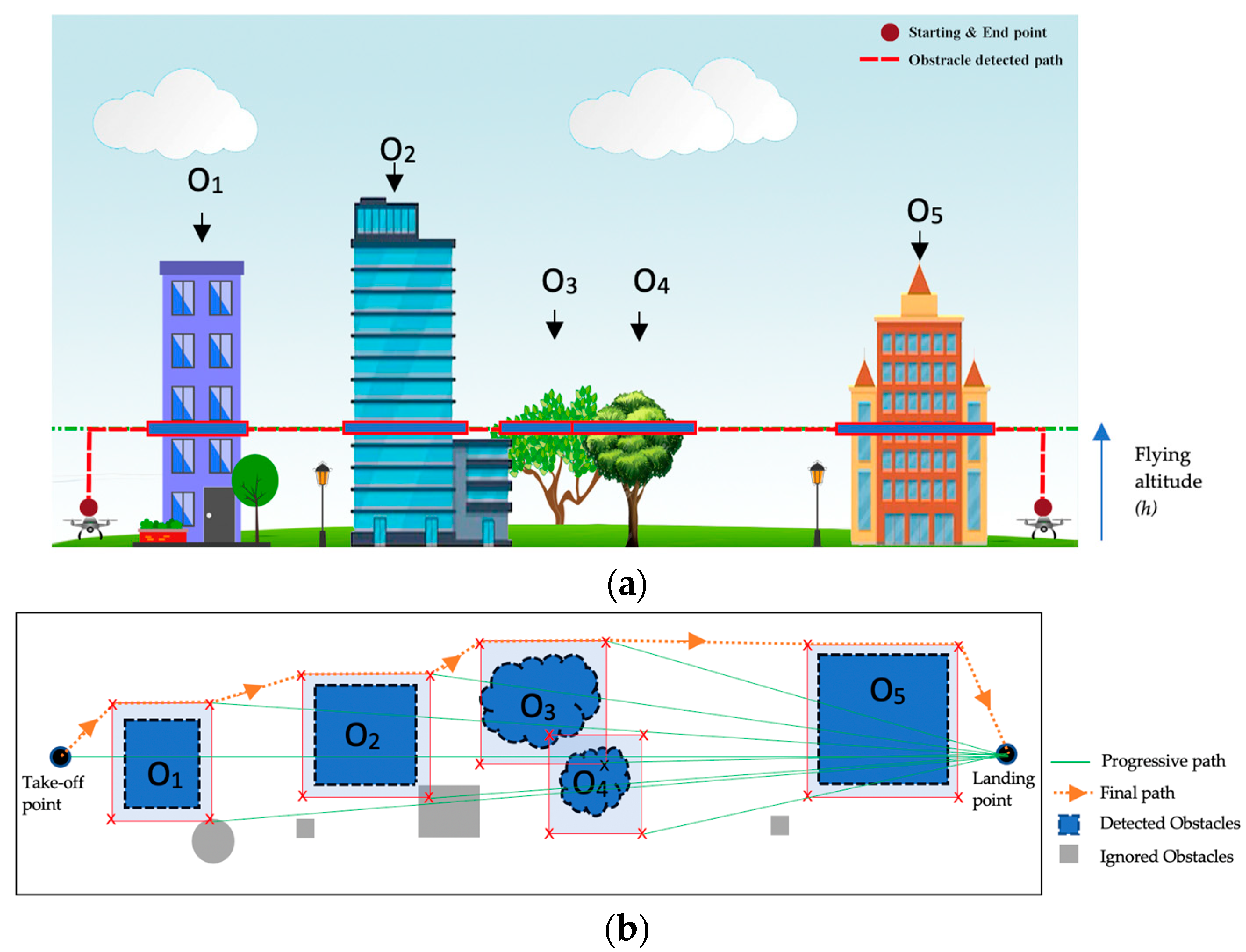
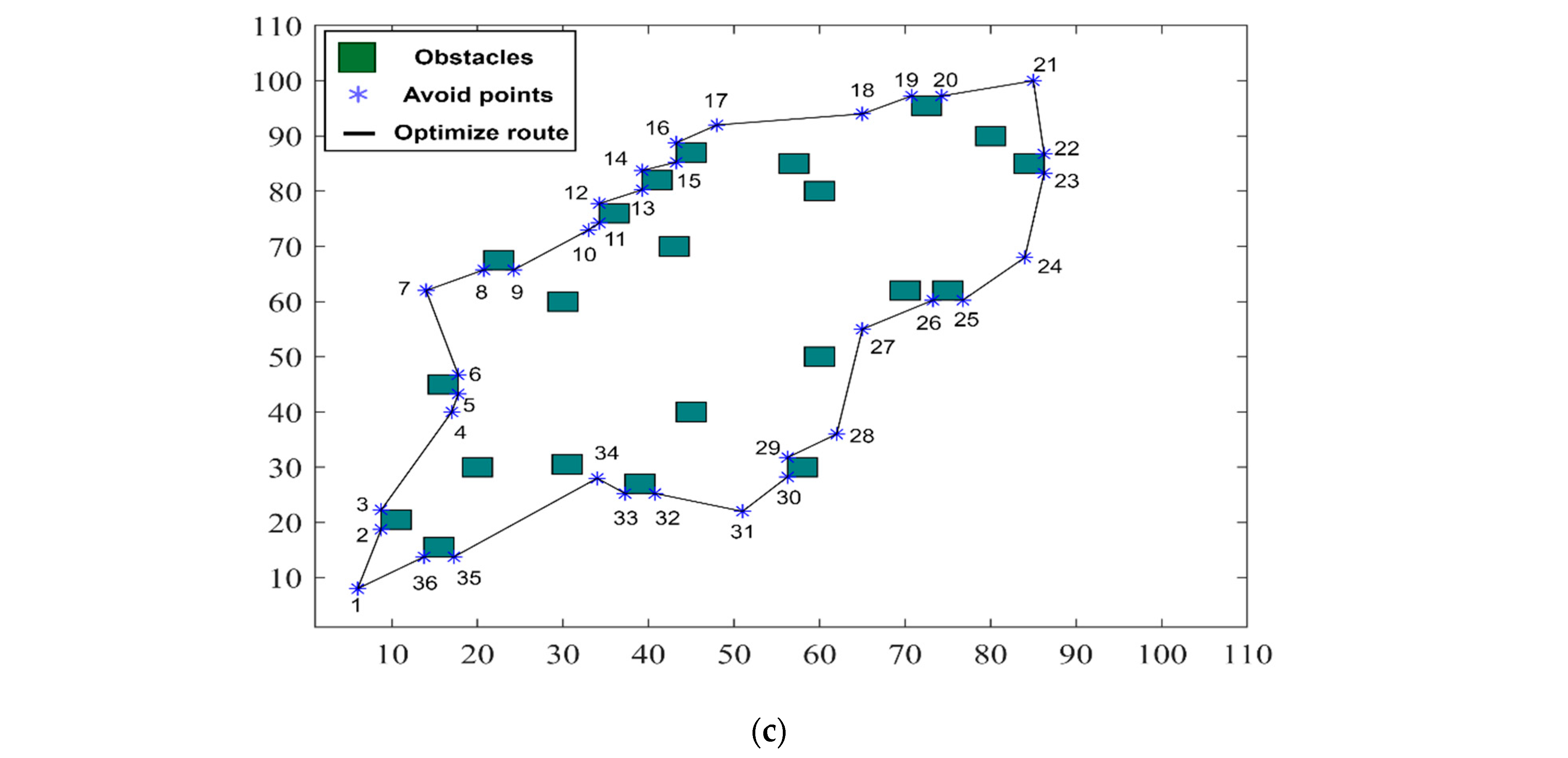
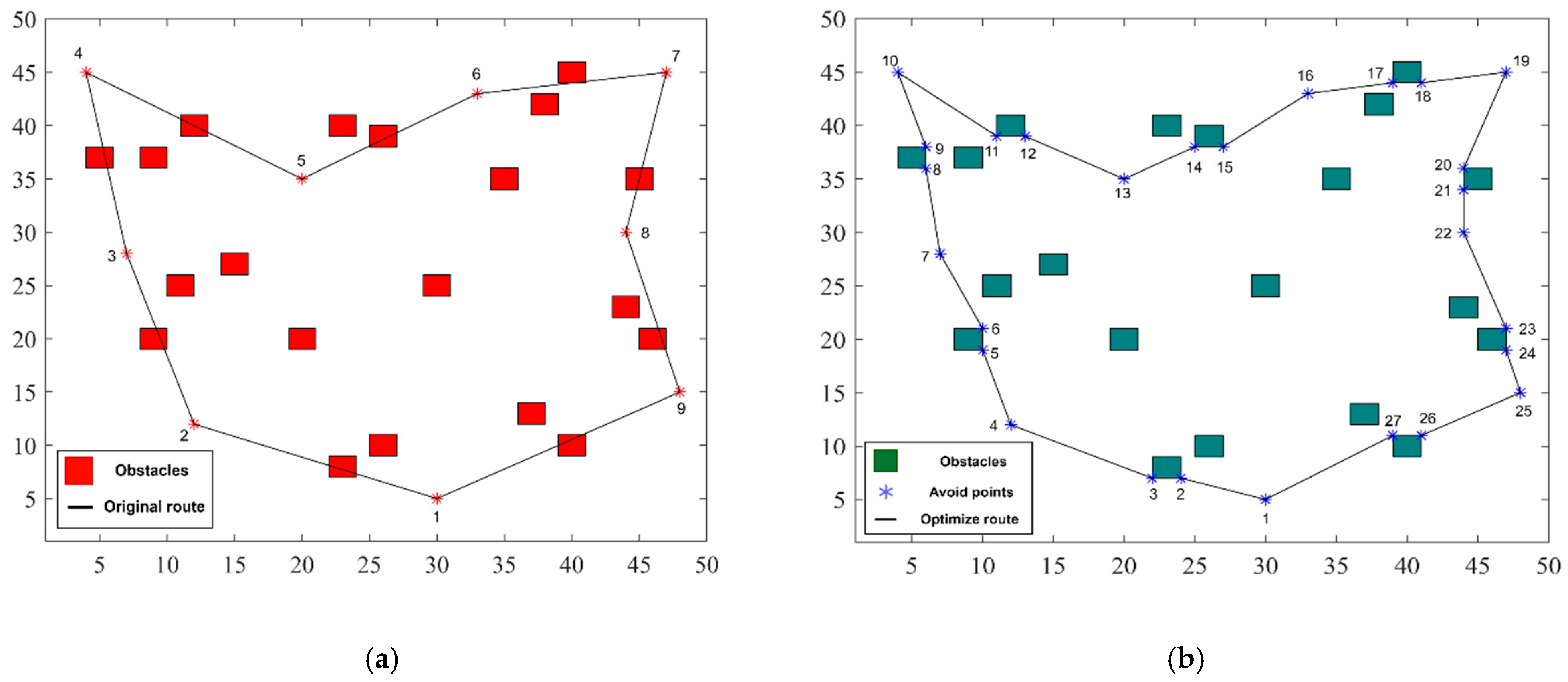
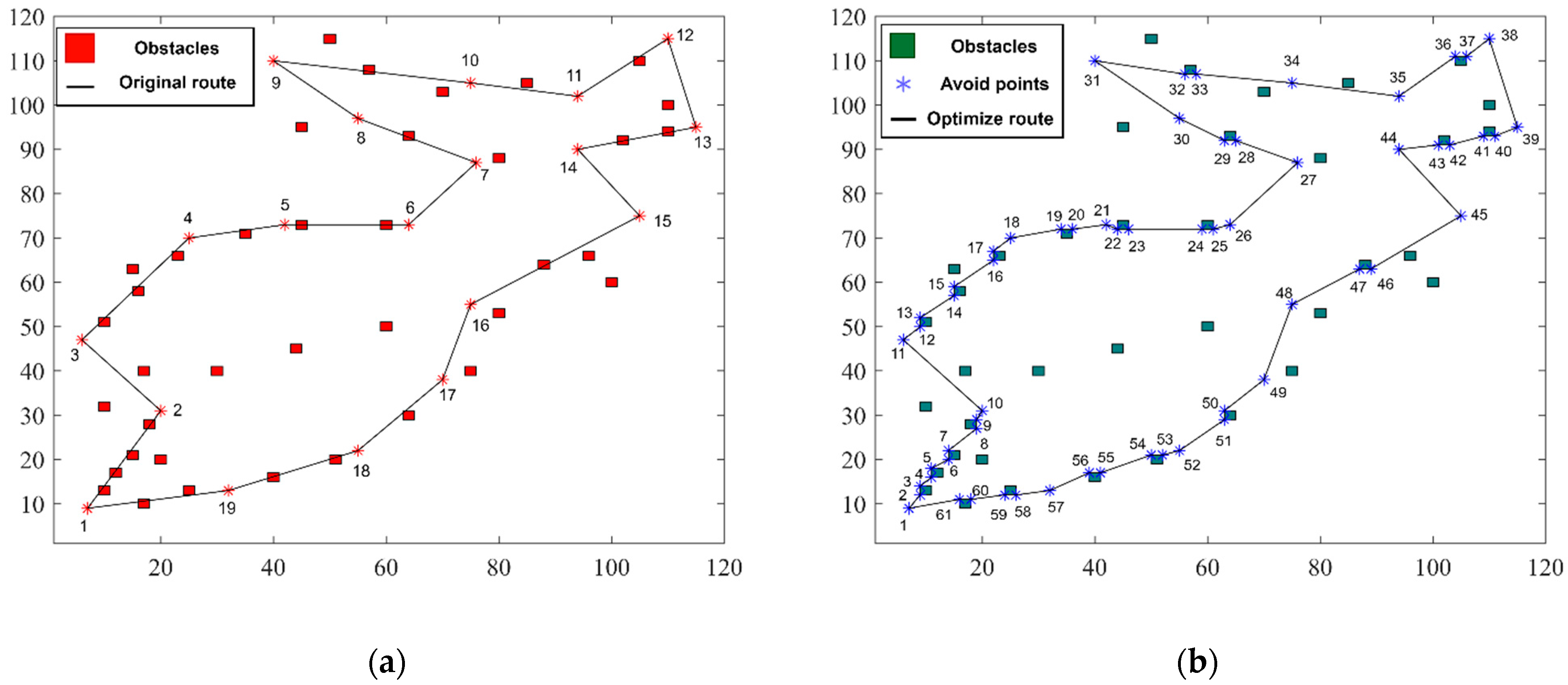
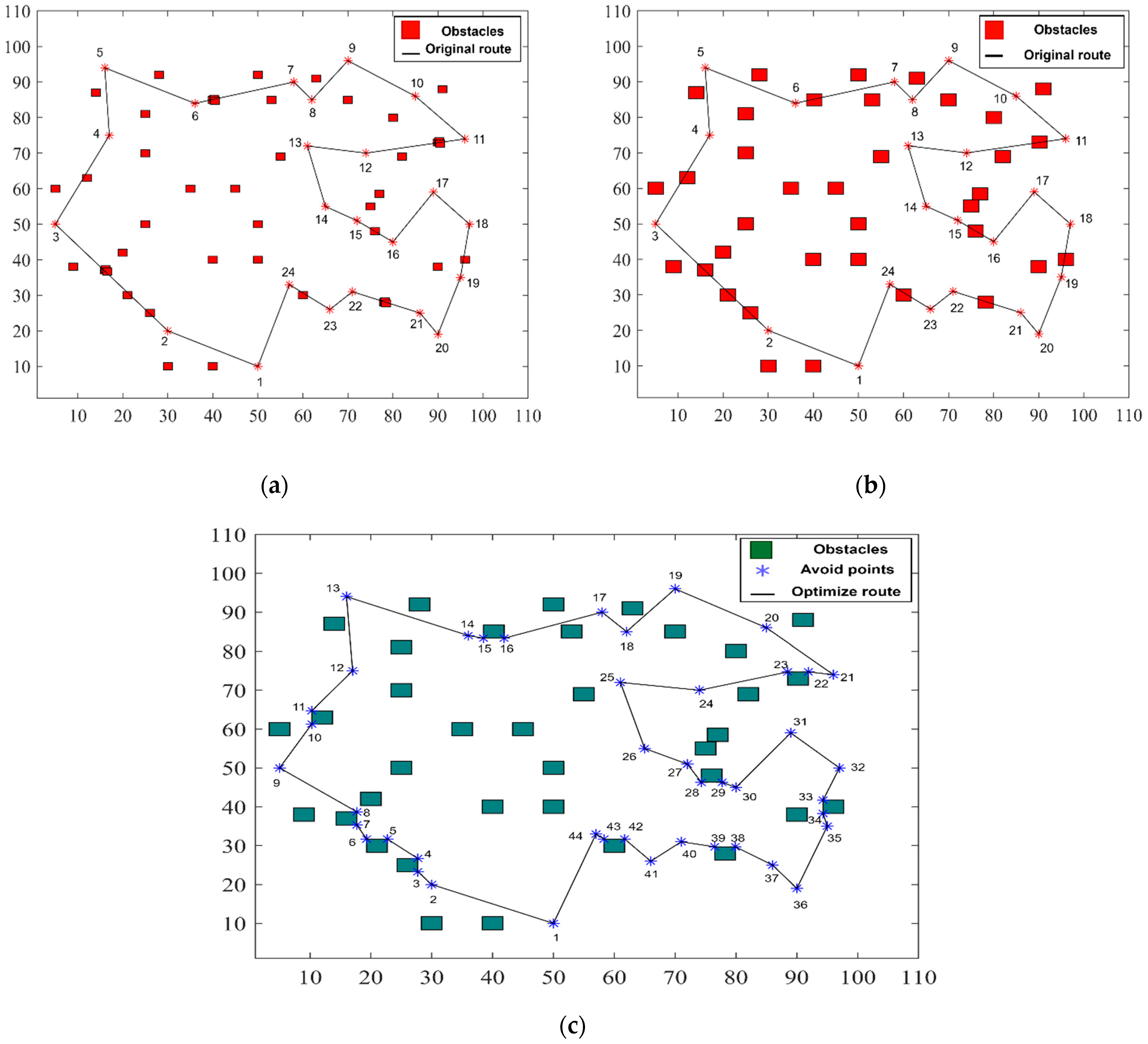
2.1. Case Studies

Our aim is to find the shortest and safest obstacle avoidance path within a given time frame, e.g., 200 s for a range of test cases. We assume restrictions are imposed to ensure compliance with the local authority as well as to ensure the flight path is planned to avoid uncertainties and issues during operation. We assume Line of Sight (LoS) operations and that the UAS must fly at a constant cruise speed of 1 m/s at a constant 10 m altitude. We also assume a 2D space. Our proposed algorithm, QuickNav, uses a geometric-based approach. We analyse the performance in terms of obstacle avoidance and distance improvement when compared to that of the brute force method [31]. The brute force method examines all the potential solutions to a problem, often by sequentially evaluating each alternative in a thorough way [32]. It is comparable to a systematic measuring procedure, where every possibility is carefully considered to calculate the outcome result. For example, assuming that a UAV has been assigned the mission of traveling to a series of predetermined locations, i.e., 1, 2, 3, 4, etc., the brute force algorithm would determine the overall distance of the path by computing the distance between each pair of adjacent points, beginning with point 1 to point 2, then 2 to point 3, and so on. The procedure continues until all the possible combinations have been analysed [33]. This approach is employed to determine the total distance of the potential path of the UAV.

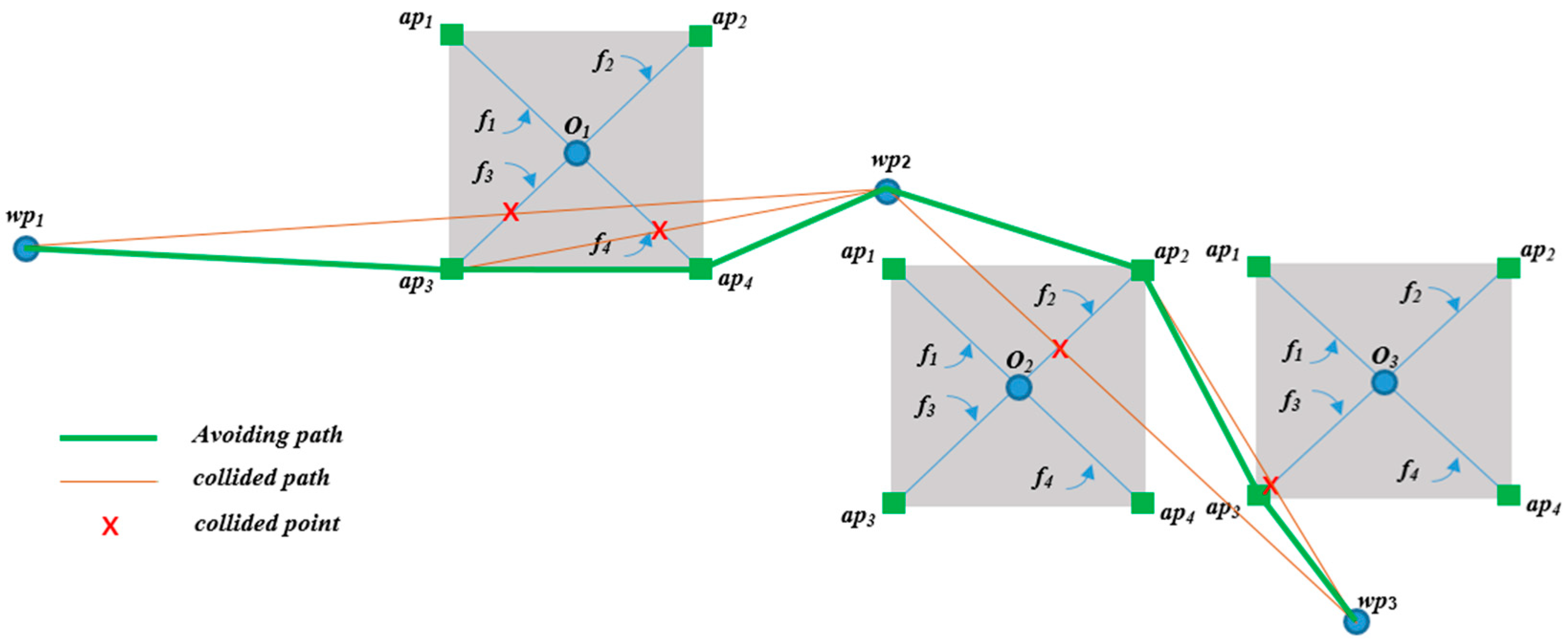
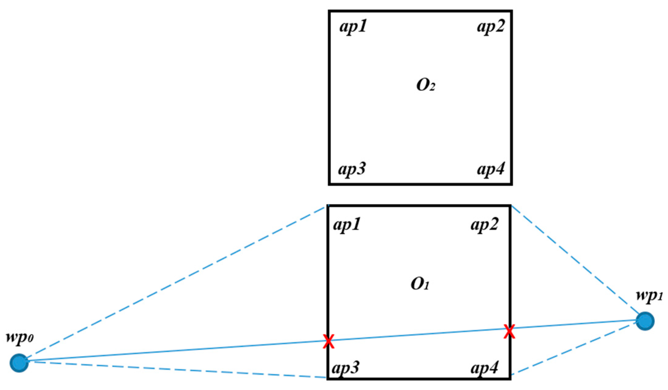
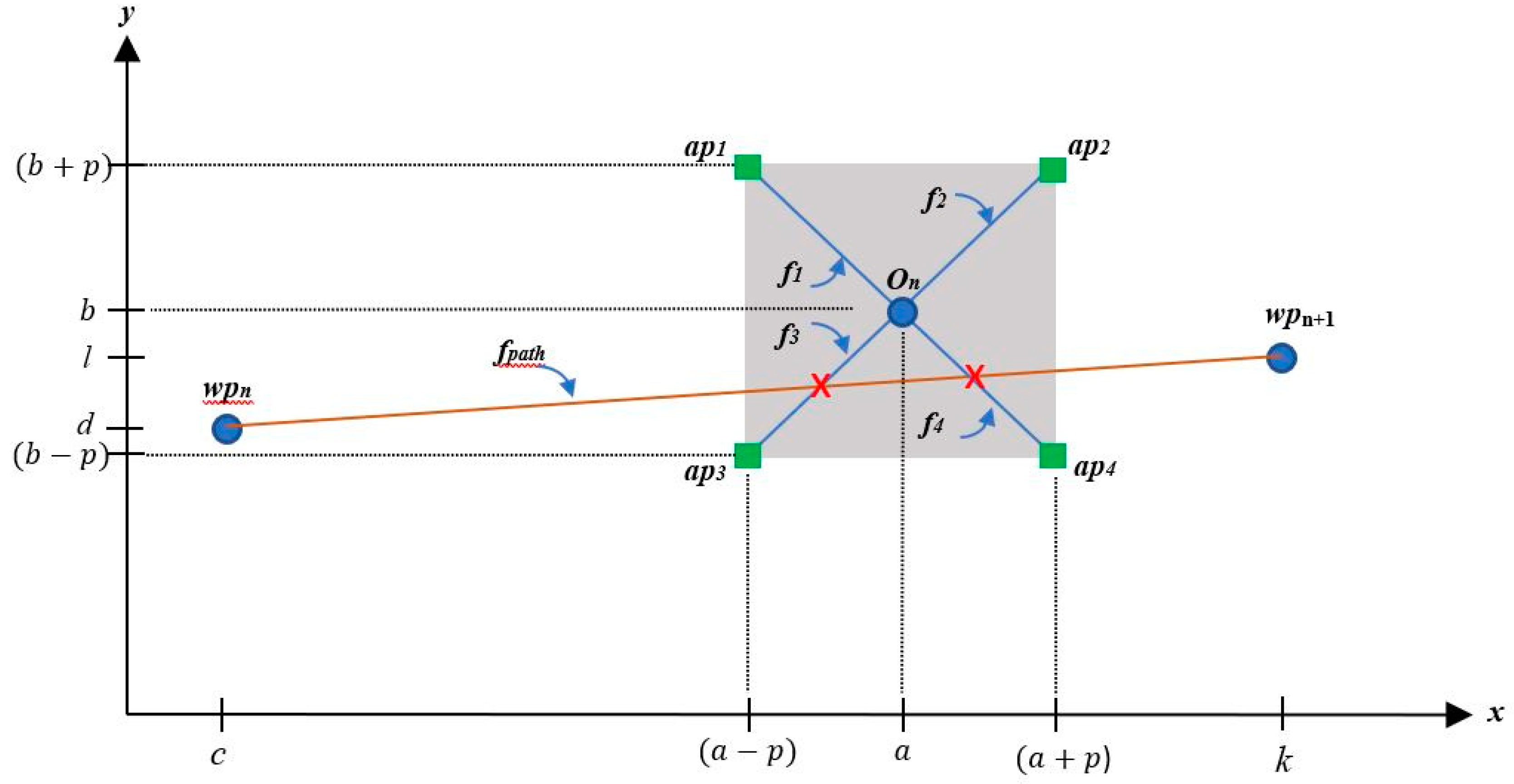
2.2. QuickNav Approach and Algorithm

The location and attitude of the UAS are two essential parameters for UAS navigation. The motion of UAS in space is determined by 6 DOFs—3 linear motions and 3 angular motions. The attitude of these parameters is controlled using an onboard flight controller. The UAV position is obtained using a Global Navigation Satellite System (GNSS), such as the Global Positioning System (GPS) presented in a latitude–longitude–altitude format. These three parameters can also be represented as x, y, and z, respectively, in the Cartesian Coordinate System (CCS).
Motion control and navigation are performed using the low-level flight controller. Path planning occurs at a higher level and is processed separately. The main function of the path planning module is to provide a series of real-time pre-planned waypoints for the low-level flight controller to manoeuvre.
As this is not an experimental approach, we formulate the problem using CCS that can later be adapted easily using GPS coordinates. In this context, parameter z represents the height or altitude, an important parameter for 3D path planning. However, this study focuses on 2D path planning and makes the assumption that the UAS flies at a fixed altitude. The z component will therefore not be computed. We propose a fast-converging, highly scalable, and computationally efficient geometrical-based obstacle detection and avoidance algorithm for a pre-planned route at a fixed altitude. The flight scenario for path planning is depicted in Figure 1. The flight scenario for path planning is depicted in Figure 1a (front view) and Figure 1b (top view). Both figures are shown as 3D images from front and top views, respectively. The obstacles (buildings, trees, etc.) are labelled as On, where n = 1, 2, 3… represents the number of obstacles, and h is the fixed flying altitude. The blue boxes in both figures represent the safe avoidance area for the drones to manoeuvre. The green lines represent the progressive line measuring the current waypoint towards the landing point. The orange (dotted with arrow) line is the final optimal path, which successfully avoids the obstacles.
The proposed algorithm requires a simulation or numerical method to detect and avoid obstacles within the environment. To reduce the complexity, we assume any obstacle points appear as a square shape in plain view. The size of the obstacles depends on the perimeter required for the UAS to manoeuvre safely. We randomly generate a series of UAS waypoints and the obstacle coordinates. We test the algorithm’s efficiency and performance by altering the number of obstacles, and classify the levels of obstacle density as low, medium, and high. We record the output avoidance path and distance. In Figure 2, we demonstrate how we consider the geometrical perspective when finding the avoidable path between waypoints (wp), e.g., between wp0 and the next waypoint, wp1.
Two obstacles, namely O1 and O2, are positioned between the two waypoints; however, O2 does not hinder the path. The proposed detection method utilizes linear equations to find the path obstacle through the interception points between obstacle perimeters and path lines. Any obstacle fences intercepted along the wp0wp1 lines will be considered as obstacles and need avoiding. The un-avoidable path is shown as a straight, solid line, and the possible avoidable paths are represented by the broken lines. In this scenario, the avoiding strategy will have at least two different avoidance routes around the obstacle O1: through the edges of the obstacle defined as avoidable point (AP) for each obstacle, AP = [ap1 ap2 ap3 ap4]. In this case, the path wp0–wp1 intercepts the fences across obstacle O1 shown by the red ‘x’. Hence, there are at least two avoidable paths available (shown by the broken lines) in the forms of wp0–O1(ap3)–O1(ap4)wp1 and wp0–O1(ap1)–O1(ap2)–wp1. The selection criteria are based on the shortest distance from wp0 to wp1. In this example, the line wp0–O1(ap3)–O1(ap4)–wp1 is the shortest available, and it is therefore selected as the avoidable path.
The algorithm computes the path and obstacles in every route iteration and compares the shortest route. Based on this concept, we formulate a method of detection using two diagonal perpendicular lines that cross the centre point of an obstacle. Then, we further split the two lines into four lines from the centre of the obstacles to every corner of the square defined as an avoidable point, respectively. These APs expand from the obstacle point via a safe perimeter defined as p, where p is the horizontal and vertical distance from the obstacle’s centre coordinate. For instance, if the path intersects with On (f3), On (ap3) will be the avoiding waypoint. Using this method, whenever a path intercepts any of the four diagonal lines, the algorithm can quickly identify the respective APs as the avoidable waypoint, as shown in Figure 3.
The algorithm takes the waypoints and obstacle centre points as inputs. From the coordinates, we create a square region from an obstacle point based on the safe distance around the obstacle as the value of p. Then, four diagonal points are created for each obstacle to form a square region (shaded).
Given the obstacle coordinate, On = (a, b), the safe flying perimeter around the obstacle centre point is p.
Using a general two-point-form linear equation, a line connecting (x1, y1) and (x2, y2) is
y y 1 = ( y 2 y 1 ) ( x 2 x 1 ) ( x x 1 )
The linear distance between two waypoints is given as:
q = [ ( x 2 x 1 ) 2 + ( y 2 y 1 ) 2 ] 1 / 2
For formulation purposes (refer to Figure 3), a flight path between two coordinate waypoints, wpn (c, d) and wpn+1 (k, l), can be formulated as:
f p a t h = ( l d ) ( k c ) [ ( x c ) + d ]   ;   s u b j e c t   t o   { c x k }
Using the same concepts for every coordinate of the obstacles, four linear equations can be formulated between the obstacle’s centre point, On (a, b), and four corresponding AP = {ap1, ap2, ap3, ap4}:
f 1 = x + a + b ;   s u b j e c t   t o   { ( a p ) x a }
f 2 = x a + b ;   s u b j e c t   t o   { a x ( a + p ) }
f 3 = x a + b ;   s u b j e c t   t o   { ( a p ) x a }
f 4 = x + a + b ;   s u b j e c t   t o   { a x ( a + p ) }
The solution to avoiding obstacles in path planning must satisfy the following Lemmas.
Lemma 1. 
A flight path between wpn and wpn+1 is said to collide with an obstacle when there is at least one interception between any obstacle’s lines, such that,
f p a t h = f 1         ;   s u b j e c t   t o { ( a p ) x a }
f p a t h = f 2       ;     s u b j e c t   t o   { a x ( a + p ) }  
    f p a t h = f 3       ;     s u b j e c t   t o   { ( a p ) x a }  
f p a t h = f 4       ;     s u b j e c t   t o   { a x ( a + p ) }    
Lemma 2. 
In every iteration, when Lemma 1 is true, the algorithm must reiterate to ensure a new route does not cross another obstacle’s line after avoidance takes place; the line that connects the edges of obstacles without intercepting any lines will be considered as the final avoidable path.
The solution to finding a new avoidable path (AP) when the path line collides with any obstacle lines is given below
A P = r = 1 r = n w p r f p a t h z = 1 z = n O z ( f 1 , f 2 , f 3 , f 5 )  
It is subject to the limit defined in (4)–(7) above.
The pseudo-code to solve the above equations is presented in Algorithm 1.
Algorithm 1: QuickNav algorithm pseudo code
Initialize

input obstacle coordinate, 0n (a, b), where n = 1,2,3…
input safe flying perimeter p,
input waypoints wpn (c, d), where n = 1,2,3…
define starting waypoint = [wp1]
define destination waypoint = [wp2]
define starting path = [ fpath ] (between starting waypoint and destination waypoint)
formulate four functions for every obstacles, On { f1, f2, f3, f4 }
define current path = starting path
define current waypoint = starting waypoint

Main

while collision detected! Check
    if <current path intercepts f1 >
        update {next waypoint candidate} = ap1
    else if <current path intercepts f2 >
        update {next waypoint candidate} = ap2
    else if <current path intercepts f3 >
        update {next waypoint candidate} = ap3
    else if <current path intercepts f4 >
        update {next waypoint candidate} = ap4
   break;
    find the nearest distance between {next waypoint candidate} and
    [current waypoint]
    update [nearest {candidate next waypoint}] = [current waypoint]
end if

while no collision detected! do
  update [current waypoint] = [destination waypoint]  //move to the next path
  update [destination waypoint] = destination waypoint ++
  update avoiding waypoint = {starting waypoint, … end waypoints}

end
There could be situations when avoiding one obstacle might cause the avoidance line to intercept with another obstacle. In this situation, the algorithm will recalculate in subsequence iterations until no interception occurs for every waypoint. The algorithm checks the current path line against the obstacle’s lines within the square region of two waypoints, e.g., wp1 and wp2, or wp2 and wp3, as illustrated in Figure 4. Initially, the path that connects wp1 and wp2 collides with the O1(f3) line. Since the path intercepts O1(f3), a new destination point is assigned, which is O1(ap3). So, a new path is created between wp1 and O1(ap3). Then, the path from O1(ap3) and wp2 collides with the line O1(f4); hence, O1(ap4) becomes a new avoidable point before it moves to wp2. In the same way, from wp2 to wp3, it collides with the O2(f2) line, and O2(ap2) becomes its avoidable point. Then, from O2(ap2) to wp3, it collides with O3(f3) so that the last avoidable point before it reaches wp3 is O3(ap3). Therefore, the final avoidable path is the path that connects wp1O1(ap3)–O1(ap4)–wp2O2(ap2)–O3(ap3)–wp3, as shown by the thick green line in Figure 4.
The process continues until all the paths on every waypoint are free from interceptions with the obstacle lines. Once the iteration ends, the successful avoidable path is plotted for visualization. In the next chapter, we will discuss the performance of the algorithm in terms of distance minimization and compare it against the brute force method. In addition, we compute the distance as compared to those of the alternate paths. In this study, we define p = 1 unit; hence, the distance of an obstacle point to the horizontal and vertical fences is 1 unit, respectively.

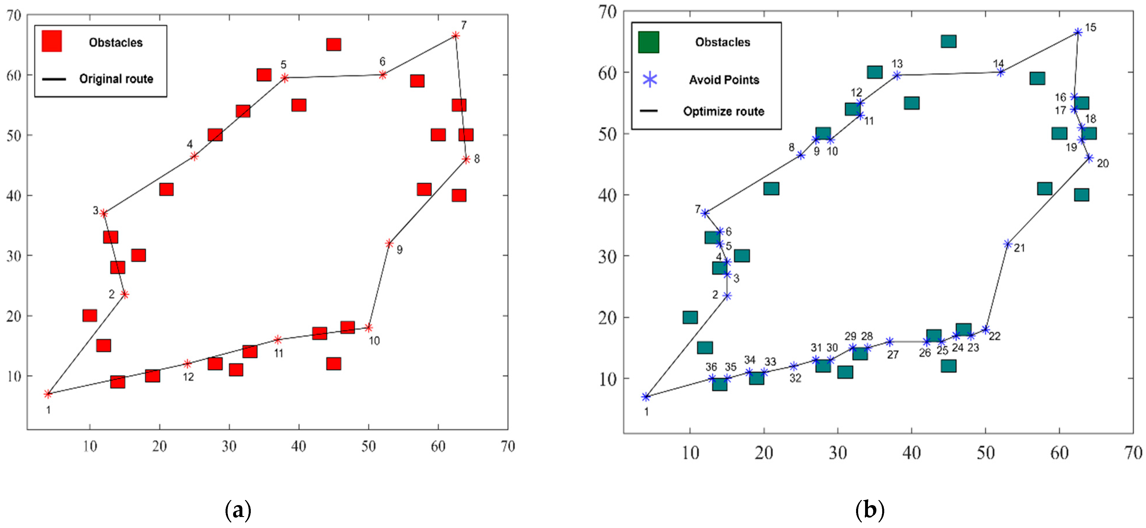
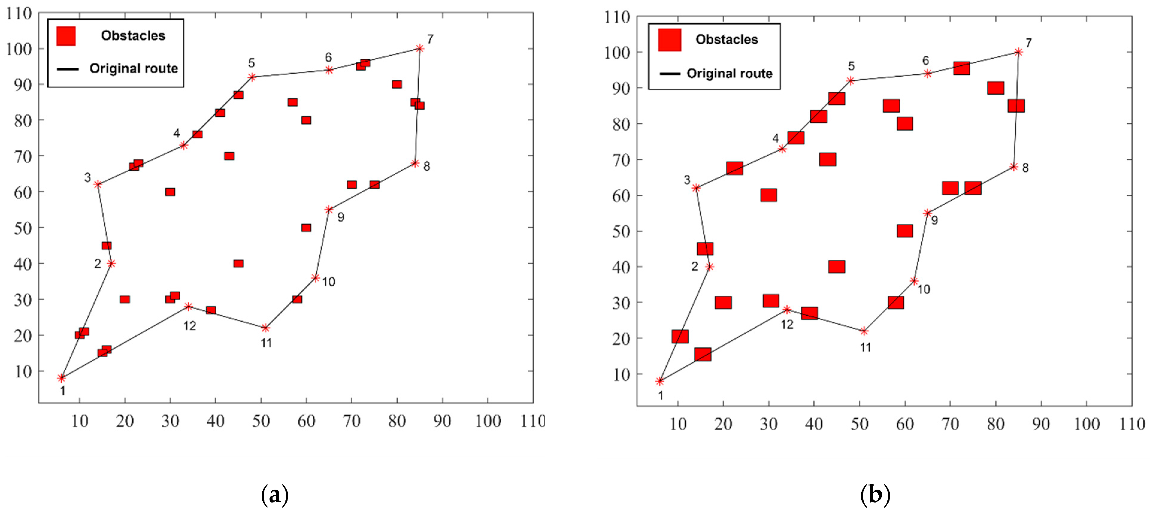
3. Results and Discussion

The QuickNav algorithm was verified for up to 44 obstacles using an arbitrary number of waypoints considered as the location points. The simulations were conducted using MATLAB. This study includes an examination undertaken to evaluate the efficacy of our algorithm through the computation of the flight time. The approach employed in this study was the calculation of the overall distance with our algorithm under the assumption of a consistent velocity of 1 m per second. The assessment was conducted using the formula t = d/s, where ‘t’ represents the flight time, ‘d’ represents the total distance acquired via the algorithm, and ‘s’ represents the assumed constant speed, and the results are presented in Table 1.
The density levels are sorted into low, medium, and high depending on the number of waypoints and obstacles (Table 1). The waypoint numbers are considered as the predefined optimized route. QuickNav took 2.58 s to compute a new route for 10 waypoints in the presence of nine detected obstacles, considering a flying time of 155 s (Figure 5). The total distance in the absence of obstacles was 153 m, which increased to 155 m for the new route planned using QuickNav to avoid the obstacles.
When the number of waypoints was increased gradually to 13, the time to compute the new route increased from 2.58 s to 9.29 s, and the total distance changed from 195 m to 197 m (Figure 6). The overall duration of the flight was observed to be 197 s. When the scenario or the number of waypoints was increased and the obstacles overlapped, the total distance increased from 285 m to 321 m for a medium-density environment.
The dimensions of the box formed are larger in the case of overlapping obstacles than those for a single obstacle to ensure that the box covers the area occupied by both the obstacles. The time to compute the new route in the medium-density environment in the presence of 17 detected obstacles was 44.70 s, which is considerably longer than that for the low-density environment (Figure 7). Additionally, the total duration of the flight was 321 s. Similarly, as the number of waypoints and obstacle numbers were further increased to 20, the time to compute the route which altogether avoided any obstacle increased to 189.10 s, and the final distance increased from 439 m to 477 m (Figure 8). At the same time, this undertaking involved a total duration of flight amounting to 477 s. In another high-density environment consisted of 25 location points, with 44 obstacles and detected 18 obstacles, it took 90.50 s to compute the total distance (Figure 9). Simultaneously, the total duration of the flight was 414 s. The time required in this case is less than that of the case with 20 obstacles, as the distance is shorter compared to that scenario.
The algorithm computation time is dependent on the number of obstacles, the number of waypoints, the total distance travelled, and if there are any overlapping obstacles. For the same number of obstacles, QuickNav computed the shortest path in the shortest amount of time feasible in the least dense environment. Furthermore, as the number of waypoints increased, the time taken to compute the new distance increased. The second important finding was that for a given set of waypoints, the computation time increased as the number of obstacles arose. This indicates that the time required to compute a new route increases according to the number of waypoints. Similarly, for a constant number of waypoints, the time taken to compute the new optimum route increased with additional obstacles.
The proposed QuickNav algorithm for obstacle avoidance in UASs/drones has several advantages. The algorithm utilizes a geometrical methodology and a preset safe perimeter to predict the intercepting points and create avoidable waypoints, allowing quick navigation around the obstacles. In addition, the predetermined secure boundary functions as a virtual fence, guaranteeing the proactive identification and evasion of obstacles, hence enhancing the safety measures and preventing collisions. QuickNav is able to generate shorter paths compared to those of the brute force approaches. This optimizes the energy consumption and extends the operating range of UAVs. Although the advantages are substantial, there are also some limitations of the proposed algorithm. The adaptability of the algorithm to complex and dynamic situations with irregular barriers may be constrained by its dependence on a geometrical approach and predetermined safe zones. Additional validation and rigorous testing across various situations are required to thoroughly determine its performance in real-world environments. Dynamic environments, varying obstacles, and unexpected changes may impact the performance. The absence of comprehensive sensing techniques could limit its adaptation.
The application of QuickNav to challenging environments would require further testing and the validation of its real-world performance and robustness. Further work could include the incorporation of sensing technologies, such as LiDAR, radar, or computer vision, to enhance the precision and adaptability of obstacle identification used by the algorithm. This integration would enable the algorithm to effectively accommodate diverse obstacle types and characteristics. The incorporation of sensors and sensor fusion methodologies (e.g., the fusion of LiDAR, radar, and cameras) would also improve its robustness to noise and disturbances. Real-world applications present challenges for implementing the proposed QuickNav algorithm. Robust testing and validation would be necessary for interactions with different UAS platforms, effective response to changing and unexpected circumstances, and the handling of unexpected obstacles. Successful implementation would require improving the accuracy of real-time obstacle detection and reducing the dependency on known areas. The utilization of filtering methods, such as Kalman filters or particle filters, could also address the issue of sensor noise. The algorithm’s navigational efficacy could be further improved by using predictive models for predicting the motion of obstacles and the impact of uncertainty.

4. Conclusions

Our QuickNav algorithm successfully generates a series of avoiding waypoints within specified time constraints. The amount of time is proportional to the problem’s complexity. QuickNav can produce a shorter distance in a faster timeframe when compared to that of the brute force method, demonstrating that QuickNav can solve difficult obstacle avoidance problems in a fraction of the time and distance compared to those of the more traditional methods. The QuickNav algorithm may have a significant impact on the future of UAS technology. QuickNav can be used to advance and automate the future of aerial operations by increasing its safety and facilitating more complex missions for UAVs in surveillance, search and rescue, and delivery services.
Future work could include the further testing of QuickNav’s performance in a range of simulated and real-world scenarios to evaluate the resilience and adaptability of the algorithm. QuickNav’s ability to learn and adapt to new obstacles or shifting surroundings could be improved via the addition of machine learning techniques. Machine learning could improve the algorithm’s decision making based on real-time data. The real-time fusion of multiple sensors could improve its environmental awareness and reduce its reliance on pre-defined safe perimeters. Reliable deployment in varied operating situations would require real-world testing and the validation of the algorithm in complex and unexpected circumstances. Collaborative swarm navigation using QuickNav-equipped UAVs could enable autonomous aerial missions and could improve UASs’ safety and efficiency in difficult conditions.

Author Contributions

Conceptualization, D.D. and A.F.H.; methodology, D.D. and A.F.H.; software, D.D.; validation, F.G., F.V.A. and M.I.R.; formal analysis, F.G.; investigation, F.V.A.; resources, A.F.H.; data curation, D.D.; writing—original draft preparation, D.D.; writing—review and editing, F.G., F.V.A. and A.F.H.; visualization, D.D.; supervision, A.F.H. and F.G.; project administration, A.F.H.; funding acquisition, F.G. All authors have read and agreed to the published version of the manuscript.

Funding

This work was supported by the RUI grant (1001/PAERO/8014162) and partially funded by the RUI Khas Grant (1001/PMEKANIK/8014032).

Data Availability Statement

The data presented in this study are available on request from the corresponding author.

Acknowledgments

The authors acknowledge continued support from the School of Aerospace Engineering, Universiti Sains Malaysia (USM), and Queensland University of Technology (QUT) through the Centre for Robotics. The authors would also like to gratefully thank the School of Aerospace Engineering USM and School of Mechanical Engineering USM for the collection and processing of MATLAB datasets that were used as a ground reference for the simulated environment. The authors extend their sincere appreciation to Scarlett Raine for her valuable help in conducting the English language review.

Conflicts of Interest

The authors declare no conflict of interest.

References

  1. Zhao, W.; Chu, H.; Zhang, M.; Sun, T.; Guo, L. Flocking control of fixed-wing UAVs with cooperative obstacle avoidance capability. IEEE Access 2019, 7, 17798–17808. [Google Scholar] [CrossRef]
  2. Bashir, N.; Boudjit, S.; Dauphin, G.; Zeadally, S. An obstacle avoidance approach for UAV path planning. Simul. Model. Pract. Theory 2023, 129, 102815. [Google Scholar] [CrossRef]
  3. Debnath, D.; Hawary, A. Adapting travelling salesmen problem for real-time UAS path planning using genetic algorithm. In Intelligent Manufacturing and Mechatronics: Proceedings of SympoSIMM 2020; Springer: Perlis, Malaysia, 2021; pp. 151–163. [Google Scholar]
  4. Tu, G.-T.; Juang, J.-G. UAV Path Planning and Obstacle Avoidance Based on Reinforcement Learning in 3D Environments. Actuators 2023, 12, 57. [Google Scholar] [CrossRef]
  5. Lin, Z.; Castano, L.; Mortimer, E.; Xu, H. Fast 3D collision avoidance algorithm for fixed wing UAS. J. Intell. Robot. Syst. 2020, 97, 577–604. [Google Scholar] [CrossRef]
  6. Yu, Y.; Tingting, W.; Long, C.; Weiwei, Z. Stereo vision based obstacle avoidance strategy for quadcopter UAV. In Proceedings of the 2018 Chinese Control and Decision Conference (CCDC), Shenyang, China, 9–11 June 2018; pp. 490–494. [Google Scholar]
  7. Du, H.; Wang, Z.; Zhang, X. EF-TTOA: Development of a UAV Path Planner and Obstacle Avoidance Control Framework for Static and Moving Obstacles. Drones 2023, 7, 359. [Google Scholar] [CrossRef]
  8. Mittal, P.; Singh, R.; Sharma, A. Deep learning-based object detection in low-altitude UAV datasets: A survey. Image Vis. Comput. 2020, 104, 104046. [Google Scholar] [CrossRef]
  9. Stulgis, A.; Ambroziak, L.; Kondratiuk, M. Obstacle detection and avoidance system for unmanned multirotors. In Proceedings of the 2018 23rd International Conference on Methods & Models in Automation & Robotics (MMAR), Miedzyzdroje, Poland, 27–30 August 2018; pp. 455–460. [Google Scholar]
  10. Lee, M.H.; Moon, J. Deep reinforcement learning-based model-free path planning and collision avoidance for UAVs: A soft actor–critic with hindsight experience replay approach. ICT Express 2023, 9, 403–408. [Google Scholar] [CrossRef]
  11. Sandino, J.; Maire, F.; Caccetta, P.; Sanderson, C.; Gonzalez, F. Drone-based autonomous motion planning system for outdoor environments under object detection uncertainty. Remote Sens. 2021, 13, 4481. [Google Scholar] [CrossRef]
  12. Komol, M.M.R.; Elhenawy, M.; Masoud, M.; Rakotonirainy, A.; Glaser, S.; Wood, M.; Alderson, D. Deep RNN Based Prediction of Driver’s Intended Movements at Intersection Using Cooperative Awareness Messages. IEEE Trans. Intell. Transp. Syst. 2023, 24, 6902–6921. [Google Scholar] [CrossRef]
  13. Hawary, A.; Razak, N. Real-time Collision Avoidance and Path Optimizer for Semi-autonomous UAVs. IOP Conf. Ser. Mater. Sci. Eng. 2018, 370, 012043. [Google Scholar] [CrossRef]
  14. Al-Kaff, A.; García, F.; Martín, D.; De La Escalera, A.; Armingol, J.M. Obstacle detection and avoidance system based on monocular camera and size expansion algorithm for UAVs. Sensors 2017, 17, 1061. [Google Scholar] [CrossRef]
  15. Zhang, J.; Yan, J.; Zhang, P.; Kong, X. Collision avoidance in fixed-wing UAV formation flight based on a consensus control algorithm. IEEE Access 2018, 6, 43672–43682. [Google Scholar] [CrossRef]
  16. Pasha, J.; Elmi, Z.; Purkayastha, S.; Fathollahi-Fard, A.M.; Ge, Y.-E.; Lau, Y.-Y.; Dulebenets, M.A. The drone scheduling problem: A systematic state-of-the-art review. IEEE Trans. Intell. Transp. Syst. 2022, 23, 14224–14247. [Google Scholar] [CrossRef]
  17. Ahmadian, N.; Lim, G.J.; Torabbeigi, M.; Kim, S.J. Collision-free multi-UAV flight scheduling for power network damage assessment. In Proceedings of the 2019 International Conference on Unmanned Aircraft Systems (ICUAS), Atlanta, GA, USA, 11–14 June 2019; pp. 794–798. [Google Scholar]
  18. Ramli, M.F.B.; Legowo, A.; Shamsudin, S.S. Object detection technique for small unmanned aerial vehicle. IOP Conf. Ser. Mater. Sci. Eng. 2017, 260, 012040. [Google Scholar] [CrossRef]
  19. Khan, M.; Hassan, S.; Ahmed, S.I.; Iqbal, J. Stereovision-based real-time obstacle detection scheme for unmanned ground vehicle with steering wheel drive mechanism. In Proceedings of the 2017 International Conference on Communication, Computing and Digital Systems (C-CODE), Islamabad, Pakistan, 8–9 March 2017; pp. 380–385. [Google Scholar]
  20. Zheng, L.; Zhang, P.; Tan, J.; Li, F. The obstacle detection method of uav based on 2D lidar. IEEE Access 2019, 7, 163437–163448. [Google Scholar] [CrossRef]
  21. Bareiss, D.; Bourne, J.R.; Leang, K.K. On-board model-based automatic collision avoidance: Application in remotely-piloted unmanned aerial vehicles. Auton. Robot. 2017, 41, 1539–1554. [Google Scholar] [CrossRef]
  22. Wan, Y.; Tang, J.; Lao, S. Research on the collision avoidance algorithm for fixed-wing UAVs based on maneuver coordination and planned trajectories prediction. Appl. Sci. 2019, 9, 798. [Google Scholar] [CrossRef]
  23. Krishnan, P.; Manimala, K. Implementation of optimized dynamic trajectory modification algorithm to avoid obstacles for secure navigation of UAV. Appl. Soft Comput. 2020, 90, 106168. [Google Scholar] [CrossRef]
  24. Patle, B.; Parhi, D.; Jagadeesh, A.; Kashyap, S.K. Matrix-Binary Codes based Genetic Algorithm for path planning of mobile robot. Comput. Electr. Eng. 2018, 67, 708–728. [Google Scholar] [CrossRef]
  25. Patle, B.; Pandey, A.; Jagadeesh, A.; Parhi, D.R. Path planning in uncertain environment by using firefly algorithm. Def. Technol. 2018, 14, 691–701. [Google Scholar] [CrossRef]
  26. Wu, P.; Xie, S.; Liu, H.; Li, M.; Li, H.; Peng, Y.; Li, X.; Luo, J. Autonomous obstacle avoidance of an unmanned surface vehicle based on cooperative manoeuvring. Ind. Robot Int. J. 2017, 44, 64–74. [Google Scholar] [CrossRef]
  27. Hu, X.; Chen, L.; Tang, B.; Cao, D.; He, H. Dynamic path planning for autonomous driving on various roads with avoidance of static and moving obstacles. Mech. Syst. Signal Process. 2018, 100, 482–500. [Google Scholar] [CrossRef]
  28. Fraga-Lamas, P.; Ramos, L.; Mondéjar-Guerra, V.; Fernández-Caramés, T.M. A review on IoT deep learning UAV systems for autonomous obstacle detection and collision avoidance. Remote Sens. 2019, 11, 2144. [Google Scholar] [CrossRef]
  29. Dhulkefl, E.; Durdu, A.; Terzioğlu, H. Dijkstra algorithm using UAV path planning. Konya J. Eng. Sci. 2020, 8, 92–105. [Google Scholar] [CrossRef]
  30. Wei, K.; Ren, B. A method on dynamic path planning for robotic manipulator autonomous obstacle avoidance based on an improved RRT algorithm. Sensors 2018, 18, 571. [Google Scholar] [CrossRef]
  31. Huang, H.; Savkin, A.V. Surveillance of remote targets by UAVs. In Proceedings of the 2021 Australian & New Zealand Control Conference (ANZCC), Gold Coast, Australia, 25–26 November 2021; pp. 222–225. [Google Scholar]
  32. Cekmez, U.; Ozsiginan, M.; Sahingoz, O.K. A UAV path planning with parallel ACO algorithm on CUDA platform. In Proceedings of the 2014 International Conference on Unmanned Aircraft Systems (ICUAS), Orlando, FL, USA, 27–30 May 2014; pp. 347–354. [Google Scholar]
  33. Hanna, S.; Yan, H.; Cabric, D. Distributed UAV placement optimization for cooperative line-of-sight MIMO communications. In Proceedings of the ICASSP 2019 IEEE International Conference on Acoustics, Speech and Signal Processing (ICASSP), Brighton, UK, 12–17 May 2019; pp. 4619–4623. [Google Scholar]
Figure 1. (a). Flight scenario within the obstacle’s environment. (Front view). (b). The obstacles cross-section at h altitude (top view) and UAS path.
Drones 07 00678 g001
Figure 2. Avoidance path between two waypoints across parallel obstacles.
Drones 07 00678 g002
Figure 3. Detection and avoidance methods using linear equation interception.
Drones 07 00678 g003
Figure 4. An example of how the algorithm solves multi-obstacle problems.
Drones 07 00678 g004
Figure 5. (a) Obstacle detection for a low-density network with 1 obstacle in a single path. (b) Obstacle avoidance for a low-density network with 1 obstacle in a single path.
Drones 07 00678 g005
Figure 6. (a) Obstacle detection for a low-density network with 2 obstacles in a single path. (b) Obstacle avoidance for a low-density network with 2 obstacles in a single path.
Drones 07 00678 g006
Figure 7. (a) Obstacle detection for medium-density network with maximum 3 obstacles in a single path. (b) Obstacle detection for medium-density network after increasing the square box ratio. (c) Obstacle avoidance for medium-density network with maximum 3 obstacles in a single path.
Drones 07 00678 g007aDrones 07 00678 g007b
Figure 8. (a) Obstacle detection for a high-density network with maximum obstacles in a single path. (b) Obstacle avoidance for a high-density network with a maximum of 4 obstacles in a single path.
Drones 07 00678 g008
Figure 9. (a) Obstacle detection for a high-density network with maximum 5 obstacles in a single path. (b) Obstacle detection for the high-density network after increasing the square box ratio. (c) Obstacle avoidance for a high-density network with a maximum of 5 obstacles in a single path.
Drones 07 00678 g009
Table 1. Simulation results.
DensityNumber of WaypointsNumber of ObstaclesUn-Avoided
Distance
(m)
Brute Force
Distance
(m)
QuickNav
Distance
(m)
QuickNav
Conv. Time
(s)
Flight Time (s)Distance Diff
Brute Force/QuickNav
(%)
Low10201531591552.581553.6/1.2
13251952111979.291978.6/1.4
Medium132728533032144.7032115.9/12.9
High2038439486477189.1047710.6/8.7
254440544541490.504149.9/2.1
Disclaimer/Publisher’s Note: The statements, opinions and data contained in all publications are solely those of the individual author(s) and contributor(s) and not of MDPI and/or the editor(s). MDPI and/or the editor(s) disclaim responsibility for any injury to people or property resulting from any ideas, methods, instructions or products referred to in the content.

