Article

Large-Sized Multirotor Design: Accurate Modeling with Aerodynamics and Optimization for Rotor Tilt Angle

1
The Ocean College, Zhejiang University, Zhoushan 316021, China
2
The Intelligent Robot Research Center, Zhejiang Laboratory, Hangzhou 311100, China
3
The State Key Laboratory of Fluid Power and Mechatronic Systems, Zhejiang University, Hangzhou 310027, China
4
The Ocean Research Center of Zhoushan, Zhejiang University, Zhoushan 316021, China
*
Author to whom correspondence should be addressed.
Drones 2023, 7(10), 614; https://doi.org/10.3390/drones7100614
Submission received: 22 August 2023 / Revised: 26 September 2023 / Accepted: 27 September 2023 / Published: 29 September 2023
(This article belongs to the Special Issue Optimal Design, Dynamics, and Navigation of Drones)

Abstract

:
Advancements in aerial mobility (AAM) are driven by needs in transportation, logistics, rescue, and disaster relief. Consequently, large-sized multirotor unmanned aerial vehicles (UAVs) with strong power and ample space show great potential. In order to optimize the design process for large-sized multirotors and reduce physical trial and error, a detailed dynamic model is firstly established, with an accurate aerodynamic model. In addition, the center of gravity (CoG) offset and actuator dynamics are also well considered, which are usually ignored in small-sized multirotors. To improve the endurance and maneuverability of large-sized multirotors, which is the key concern in real applications, a two-loop optimization method for rotor tilt angle design is proposed based on the mathematical model established previously. Its inner loop solves the dynamic equilibrium points to relax the complex dynamic constraints caused by aerodynamics in the overall optimization problem, which improves the solution efficiency. The ideal design results can be obtained through the offline process, which greatly reduces the difficulties of physical trial and error. Finally, various experiments are carried out to demonstrate the accuracy of the established model and the effectiveness of the optimization method.

1. Introduction

For the past half century, multirotor unmanned aerial vehicles (UAVs) have developed rapidly and have been successfully applied in the fields of aerial photography, industrial inspection, and precision agriculture [1,2,3]. However, most of the current applications are based on small-sized multirotors, which have limited available space and load capacity. In contrast, large-sized multirotors have stronger power and larger space, which can expand their application scope to transportation, logistics, rescue, and disaster relief [4,5]. To promote so-called advancing aerial mobility (AAM) [6,7,8], the key concern for large-sized multirotors is their endurance and maneuverability.
To improve the flight performance of multirotors, including endurance and maneuverability, the design of the rotor tilt angle is an effective and simple method. For example, fully actuated multirotors usually adopt this design to achieve six-degrees-of-freedom (DoF) movement [9,10]. This type of design changes the direction of the force and torque generated by the actuator by tilting the rotor to achieve different design goals. In general terms, a dihedral angle can improve the hovering stability [11], and a cant angle can improve the maneuverability of the yaw motion [10,12]. However, the rotor tilt angle design sacrifices the lift force, and the output forces of tilted rotors partially cancel each other out, so an incorrect design may even result in reduced flight performance.
For the design of general multirotors, various methods have been proposed in the literature. Most studies focus on the sizing and selection of propulsion system components, according to different design requirements, such as flight maneuverability [13], battery endurance [14,15], safety and reliability [16], design automation [17], etc. As for the rotor tilt angle design, the dynamic manipulability measure method is proposed in [10] for hexrotors considering tilt angles and the arrangement of rotors. In [18], a numeric estimation and optimization method is presented for the dynamic performance of multirotors with tilted rotors.
However, the design methods mentioned above are targeted towards small- or medium-sized multirotors. In fact, in addition to the inherent complex characteristics of multirotors, such as motion coupling, the design of large-sized multirotors presents more difficulties and challenges than the design of small-sized ones. This is because the increase in size leads to a larger effect of nonlinearities and uncertainties that can be neglected in small-sized multirotors, including center of gravity (CoG) offset, aerodynamics, and actuator dynamics. On the other hand, large-sized multirotors are not convenient for physical trial and error designs, which puts forward higher requirements for the effectiveness of the design method and the accuracy of the mathematical model used in the design.
In other words, accurate modeling is important for the design of large-sized multirotors. First of all, an accurate rigid-body dynamic model can be established based on Newton–Euler equations [19,20], including the factors of CoG offset and the positions of rotors. In [21,22], actuator dynamics is also considered to improve the flight control performance of multirotors. As for the modeling of aerodynamics, which is complex but important, a gray-box aerodynamics model is identified for quadrotors in [23] based on high-speed flight data. In [24,25], the finite element analysis technique is used to analyze the aerodynamic effects of actuators. Furthermore, a general explicit mathematical model of aerodynamics is required for the design of multirotors. The simplified mathematical model of aerodynamics is adopted in [26]. In [27,28], an accurate model of the aerodynamics of a rotor is derived in detail. In addition, blade flapping and coaxial effects are analyzed in [29] and [30], respectively.
In this study, in order to improve the effectiveness of offline design and reduce physical trial and error for large-sized multirotors, a dynamic model of large-sized multirotors is established in detail, including accurate rigid-body dynamics, aerodynamics, and actuator dynamics. Then, to improve the endurance and maneuverability of large-sized multirotors, the optimization method for rotor tilt angle design is introduced based on the established mathematical model. The main contributions of this study can be summarized in the following three points.
1. A dynamic model of large-sized multirotors is established accurately for use in offline design or parameter tuning. The CoG offset, aerodynamics, and actuator dynamics are well considered, which are neglected in small-sized ones. The high accuracy of the established mathematical model is verified through experiments.
2. A two-loop optimization method for rotor tilt angle design is proposed based on the accurate dynamics model to improve endurance and maneuverability. Specifically, the inner loop is introduced to solve the equilibrium points of dynamic equations. This actually relaxes the complex constraints caused by aerodynamics, so the overall optimization problem can be solved effectively. In addition, the proposed method can also be extended to other design tasks.
3. Benefiting from the highly accurate dynamic model and the efficient optimization method, ideal design results can be obtained through the offline process, which greatly reduces the difficulties of physical trial and error. Simulations and experiments are conducted to verify that the optimized design improves the maneuverability and endurance of large-sized multirotors.
The rest of this paper is organized as follows. In Section 2, the accurate dynamic model of the multirotors is established, including rigid-body dynamics, aerodynamics, and actuator dynamics. The optimization method for rotor tilt angle design, with its motivation and purpose, is introduced in Section 2. In Section 4, various experiments are carried out to demonstrate the accuracy of the established model and the effectiveness of the optimization method. Finally, conclusions are drawn in Section 5.
Notation 1. 
R > 0 represents a positive definite matrix. Given a , b R 3 , a × represents the skew–symmetric matrix of a that satisfies a × b = a × b . The inverse operation of × is denoted as , i.e., a × = a . The unit vector of the z -axis is denoted as n z = 0 0 1 T .

2. System Modeling

In this section, the dynamics models are analyzed in detail. In addition to the rigid-body dynamics of multirotors and the mechatronic dynamics of motors, the aerodynamics of propellers, including the effect of rotor tilt angles, is also carefully considered, which is usually ignored for small-sized multirotors but is crucial for large-sized multirotors.

2.1. Rigid-Body Dynamics

To develop the rigid-body dynamics model of multirotors, coordinate systems are defined as shown in Figure 1. Let I represent the north–east–down (NED) inertia reference frame, and B represent the forward–right–down (FRD) body-fixed frame.
Let p = x y z T R 3 and v = u v w T R 3 denote the position and velocity expressed in frame I , respectively. R S O ( 3 ) represents the rotation matrix from frame B to frame I , and ω = p q r T R 3 is the angular velocity expressed in frame B . According to Newton–Euler equations [19], the rigid-body dynamics of multirotors can be established as follows:
p ˙ = v
m v ˙ = m g n z + f r + f u
R ˙ = R ω ×
J ω ˙ = ω × J ω + τ r + τ u
with
f r = m R ω ˙ × + ω × ω × r g
τ r = m r g × R T v ˙ g n z
in which g R + is the gravity constant; m R + and J R > 0 are the mass and the inertia tensor of the multirotors, respectively; r g R 3 denotes the center of gravity (CoG) vector; f r R 3 and τ r R 3 are the force and torque caused by r g , respectively; and f u R 3 and τ u R 3 are the resultant force and torque generated by the propellers, respectively.
Remark 1. 
The resultant force f u and torque τ u generated by the propellers vary according to the configuration of the multirotors. They are determined by the position and attitude (i.e., the tilt angles) of each rotor, which further affect the manipulation characteristics of the multirotors.

2.2. Aerodynamics

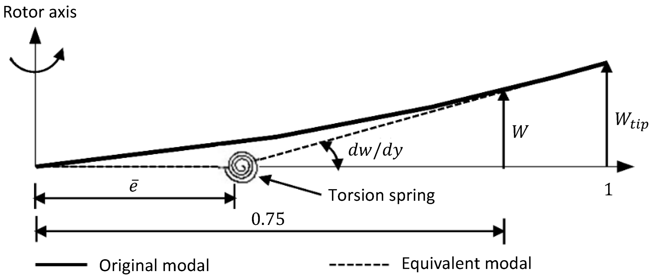
2.2.1. Blade Flapping

For large-sized multirotors, the blade flapping effect cannot be ignored. Based on the equivalent torsion spring approximation shown in Figure 2, the first-order harmonic approximation of the blade flapping motion can be expressed as
β = a 0 a 1 cos φ b 1 sin φ
where β is the blade flapping angle; φ is the blade direction angle expressed in the wind-axis frame; a 0 is the blade taper angle; and a 1 and b 1 are the longitudinal and lateral periodic flapping coefficients in the wind-axis frame. According to [29,30], the blade paddle dynamics can be described as follows.
a ¨ 0 a ¨ 1 b ¨ 1 + D a ˙ 0 a ˙ 1 b ˙ 1 + K a 0 a 1 b 1 = f
where D is the damping matrix, K is the stiffness matrix, and f is the excitation vector. D , K , and f are obtained by solving the moment balance equations acting on the equivalent flapping hinge, and the details are presented in [29,30].

2.2.2. Propeller Aerodynamics

The aerodynamics acting on the propeller is calculated using the blade element method, considering the blade flapping. Let T, H W , and Y W be thrust, rearward, and lateral force, respectively. The aerodynamic forces are expressed as
T = i = 1 b κ 0 R e F 1 φ i d r b M β a ¨ 0 + m b g m b w ˙ u q + p v
H W = i = 1 b 0 R e F 3 φ i sin φ i d r κ 0 R e F 2 φ i sin φ i + F 1 φ i β i cos φ i d r
Y W = i = 1 b 0 R e F 3 φ i cos φ i d r + κ 0 R e F 2 φ i cos φ i F 1 φ i β i sin φ i d r
Let L W , M W , and Q be heading, pitch, and roll torque, respectively. The aerodynamic torque is expressed as
Q = i = 1 b 0 R e e + r F 3 φ i d r κ 0 R e e + r F 2 φ i d r + I M R Ω ˙
M W = i = 1 b κ 0 R e e F 1 φ i cos φ i d r + e M β β ¨ i K β β i cos φ i
L W = i = 1 b κ 0 R e e F 1 φ i sin φ i d r + e M β β ¨ i K β β i sin φ i
in which R is the rotor radius; b is the number of blades; e is the offset of the blade flapping hinge; r is the radial length from the blade profile to the flapping hinge; κ is the tip loss coefficient; m b is the blade mass; M β is the moment of inertia of the blade about the flapping hinge; K β is the spring stiffness of the flapping hinge; and I M R is the moment of inertia of the rotor. In addition, the details of F 1 φ i , F 2 φ i , and F 3 φ i are described in [27,28].
Remark 2. 
For the coaxial multirotors, as shown in Figure 1, we assume that the induced inflow of the lower propeller does not affect the ability of the upper propeller to generate thrust, and the propellers are sufficiently close together that the wake from the upper propeller does not fully develop. This assumption is based on [31], and it has been proven that it has acceptable precision because the coaxial rigid rotors usually feature very stiff blades with a small separation distance between rotors.

2.2.3. Airframe Aerodynamics

The airframe aerodynamics is calculated through the experimental data of the wind tunnel. The angle of attack, the sideslip angle, and the dynamic pressure of the airframe take into account the aerodynamic disturbance effect of the rotors.
Let v f = u f v f w f T R 3 denote the relative air velocity at the aerodynamic center of the airframe, which can be calculated as follows.
v f = v + ω × r f + v i w f
in which r f is the position vector from the aerodynamic center to the geometric center, and v i w f is the aerodynamic disturbance effect of the rotors, which is determined through comprehensive ground tests on multirotors. These experiments directly measure the aerodynamic interference between rotors. The v i w f value for various operational conditions is calculated using a look-up-table approach. Then, the angle of attack and sideslip of the airframe are
α f = arctan w f u f , β f = arctan v f u f 2 + w f 2
and the dynamic pressure at the aerodynamic center is
q f = 1 2 ρ u f 2 + v f 2 + w f 2
where ρ is the local atmospheric density.
In the body frame, the total airframe aerodynamics acting on multirotors is
X F Y F Z F = T f q f C D F q f C Y F q f C L F , L F M F N F = T f q f C R F q f C M F q f C N F + r f × X F Y F Z F
in which
T f = cos α f 0 sin α f 0 1 0 sin α f 0 cos α f cos β f sin β f 0 sin β f cos β f 0 0 0 1
and the airframe aerodynamic coefficients C L F , C D F , C Y F , C R F , C M F , and C N F are all expressed as functions of the angle of attack and sideslip, which can be obtained from the wind tunnel experimental data.

2.3. Actuator Dynamics

The propellers are driven by brushless DC (BLDC) motors with the well-known mechatronic dynamics model [22].
L m I ˙ = U R m I k e ω m
J m ω ˙ m = k m I τ d k v ω m k s
where U R and I R are the voltage and current of the motors, respectively; ω m R is the rotation speed of the motors; R m R + and L m R + are resistance and inductance, respectively; J m R + is the inertia of the motors; k e R + is the back electromotive force (EMF) constant; k m R + is the electromagnetic torque constant; k v R + is the viscous friction constant; k s R + is the solid friction constant; and τ d R is the load of the motors, which can be obtained from the aforementioned aerodynamics of the propellers.

3. Rotor Tilt Angle Design

The main results are presented in this section. The motivation and purpose of the design are clarified first, followed by the introduction to the optimization method based on the aerodynamics model established in the previous section.

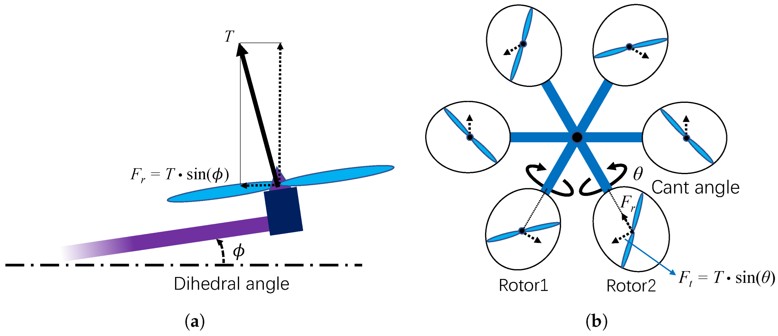
3.1. Motivation and Purpose

For multirotors, the rotor tilt angles have two degrees of freedom (DoF) that can be designed, i.e., the dihedral angle ϕ R and the cant angle θ R , as shown in Figure 3.
Generally, dihedral angle design is achieved by pitch tilting the rotor arms, as shown in Figure 3a. As a result, part of the driving force T generated by the rotor is decomposed into an inwardly directed normal component F r , which can improve the hovering stability of multirotors. As for the cant angle design, the adjacent rotors are tilted in opposite directions by the same amount of rolling, as shown in Figure 3b. Moreover, the generated additional tangential component force F t improves the maneuverability of the yaw motion for the multirotors.
However, both types of rotor tilt angle designs sacrifice the lift force for the component forces in other directions, and these component forces partially cancel each other out, which may reduce the energy efficiency of the multirotors. In addition, the rotor tilt angle design may strengthen the coupling effect between the position and the attitude control. Based on these considerations, the purpose of the design is to find the optimal rotor tilt angles that balance the movement of each DoF and improve the overall endurance and maneuverability of the multirotors.

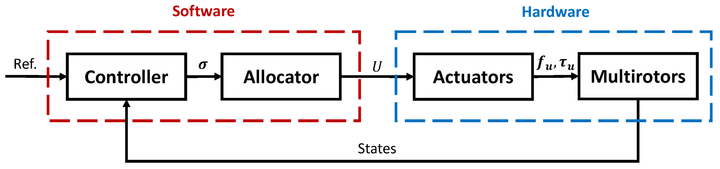
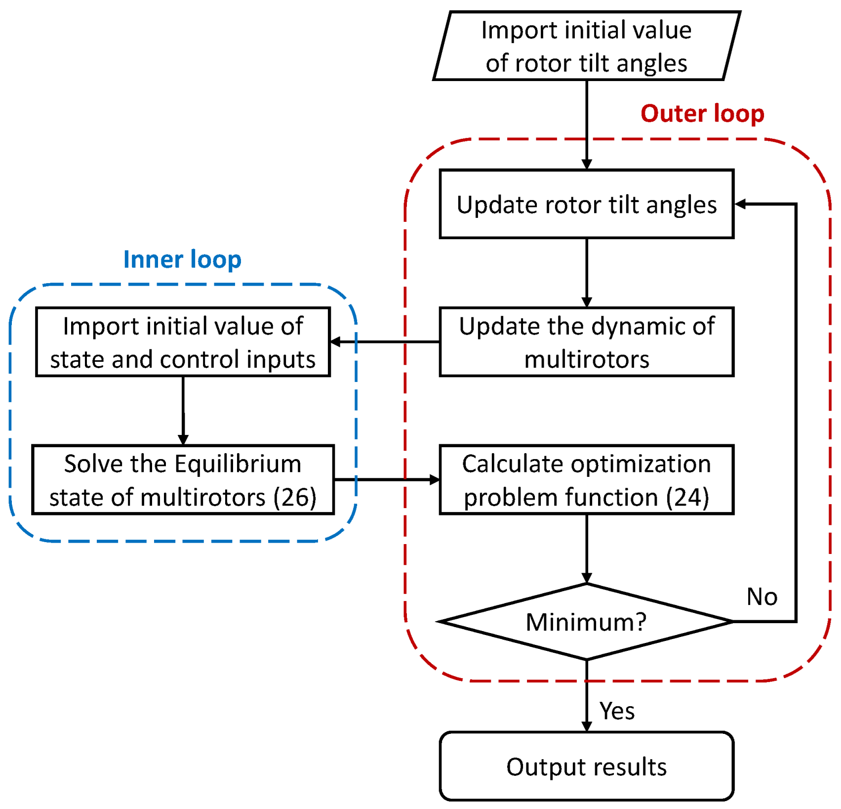
3.2. Optimization Method

To construct the optimization problem, the common control architecture for multirotors is introduced, as shown in Figure 4, which is adopted by many popular open-source flight controllers, such as PX4 [32].
As shown in Figure 4, the control architecture includes two parts, i.e., software and hardware. The principle of the hardware is described in the modeling section. In the software part, the output of the controller module is the normalized control input for each DoF, as indicated by σ in Figure 4. For underactuated multirotors, this is σ R 4 ; for omnidirectional multirotors, it is σ R 6 . Then, the allocator module allocates the normalized control input to each actuator and modulates it into the corresponding voltage value U.
Specifically, the classical geometric control method [33] is adopted. The desired control input force f u d and torque τ u d are chosen as follows:
f u d = k p e p k v e v m g n z f r + m x ¨ d
τ u d = k r e r k ω e ω + ω × J ω τ r + J ω ˙ d
in which k R 3 are the control gains; x d , ω d R 3 are the desired position and angular velocity, respectively; and e R 3 are the state errors defined as in [33].
According to the maximum capacity of actuators, the desired f u d and τ u d can be normalized to σ as mentioned above. Then, based on the force and moment constants of the actuator and the geometry of the airframe, the so-called control allocation matrix M x can be obtained and the input voltage U of each actuator can be determined through U = M x 1 σ .
For a specific flight mission, if a certain DoF of σ is relatively lower, this means that this DoF has a higher control margin and less power consumption, i.e., the endurance and maneuverability of this DoF are better. In order to balance each DoF and achieve the best overall performance in terms of endurance and maneuverability, the following optimization problem is constructed.
min ϕ , θ E = σ T W σ
s . t . Equations ( 1 ) ( 21 ) v = v d ϕ m i n < ϕ < ϕ m a x θ m i n < θ < θ m a x
where W is the diagonal weight matrix; m a x and m i n are the maximum and minimum for •, respectively; and v d R 3 is the desired velocity for a specific flight condition.
The optimization variables of problem (24) are the rotor tilt angles, and the constraints include the system dynamics (1)–(21) established in the modeling section. Since the system dynamics considers accurate aerodynamics, the result of problem (24) is very close to reality, which reduces the trial and error costs.
However, it is also very difficult to solve problem (24) directly due to the complex dynamics (1)–(21), so the two-loop solution is proposed, as shown in Figure 5. In the inner loop, the complex dynamics (1)–(21), including the effect of aerodynamics, is solved by means of the numerical optimization method in order to obtain the equilibrium state of the multirotors. In other words, we solve the following nonlinear optimization problem:
min R , f u , τ u , σ m g n z + f r + f u W p 2 + ω × J ω + τ r + τ u W ω 2
s . t . Equations ( 5 ) ( 21 ) v = v d ω = 0
where W p and W ω are weight matrices. Note that f r and τ r are calculated according to (5) and (6), respectively, and f u and τ u are subject to the constraints of (7)–(21), including aerodynamics and actuator dynamics. In this way, the first and second constraints (25) in the original optimization problem (24) are actually relaxed.
In the outer loop, relying on the solution of the inner loop, problem (24) is solved based on sequential quadratic programming (SQP) [34]. This is an iterative method used for nonlinear optimization that approximates the nonlinear constraints and objective function with quadratic functions. At each iteration, SQP solves a quadratic programming (QP) subproblem based on a linearized model of the constraints (25) and a quadratic model of objective (24), and the solution obtained provides a search direction for the updating of the current estimate of the optimal solution, i.e., Δ ϕ k and Δ θ k . The update formulas for the dihedral angle and cant angle are
ϕ k + 1 = ϕ k + η k Δ ϕ k
θ k + 1 = θ k + η k Δ θ k
in which η k is the step size.
Remark 3. 
For the numerical optimization solution of the inner loop, a simulation model is built based on the established mathematical models, using Matlab Simulink, as shown in Figure 7 in the next section. Then, the Matlab trim() function is used to generate the trim states and trim inputs for the simulation model.

4. Experimental Verification

The rotor tilt angle design for manned multirotors is presented as a case study in this section. A coaxial multirotor with eight rotor arms and sixteen propellers, as shown in Figure 1 and Figure 6, is chosen for design and experimental verification. Firstly, the dynamics model is verified, as it is the basis for the proposed design method. Then, the rotor tilt angles are designed using the proposed design method.
In order to verify the mathematical model established in Section 2, and for the subsequent design process, the simulation platform for the multirotors is established as shown in Figure 7. Furthermore, the sensor noise and battery consumption are also considered to simulate the real multirotor as much as possible, in addition to rigid-body dynamics, aerodynamics, and actuator dynamics.

4.1. Model Verification
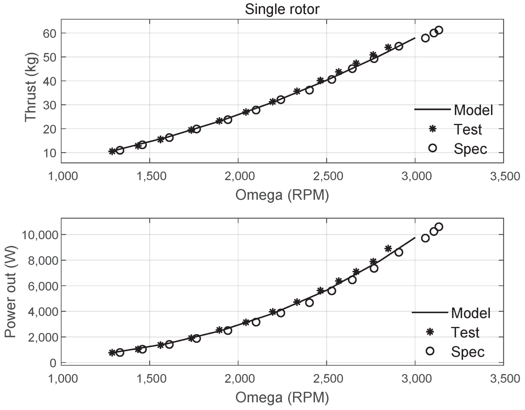
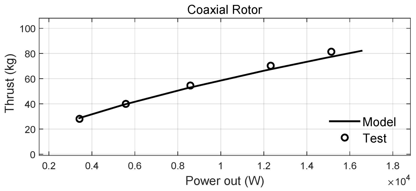
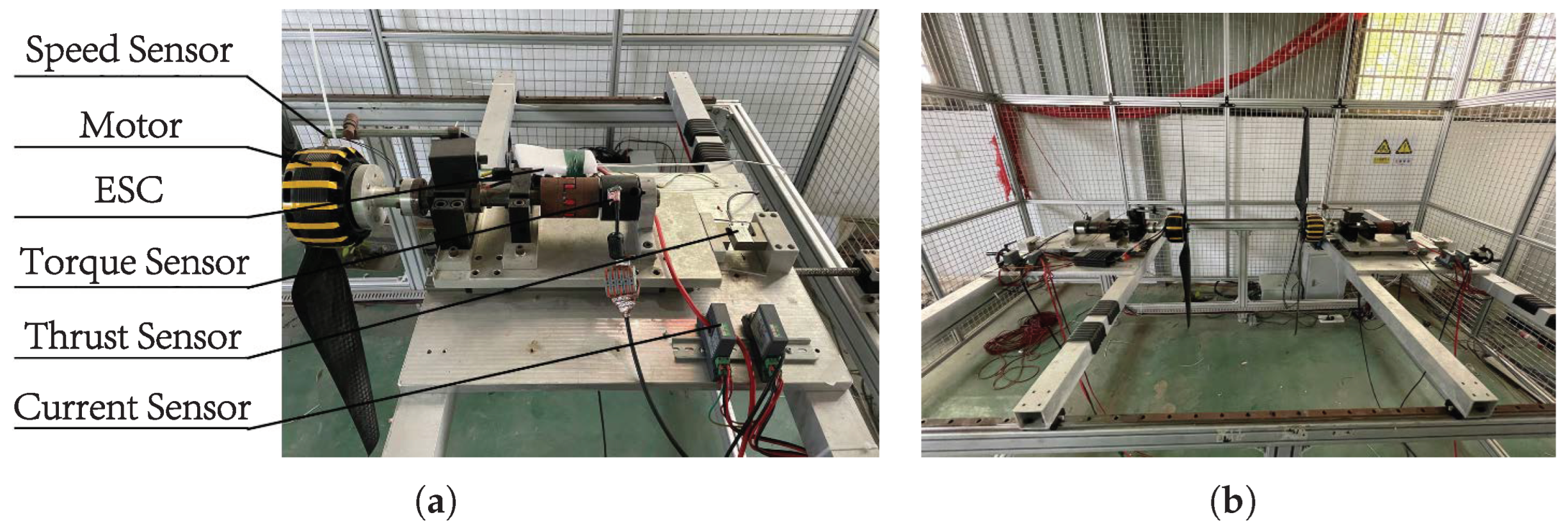
4.1.1. Rotor Tests

To test the steady-state and transient performance of the actuators, the actuator test bench was designed as shown in Figure 8. The single-rotor test bench is illustrated in Figure 8a. Compared to the actuator mounted on a multirotor, the test bench can provide additional information on the rotational speed, thrust, torque, and current. The coaxial rotor test bench, shown in Figure 8b, is composed of two single-rotor test benches. The incorporated slide rail facilitates the easy adjustment of the distance between the rotors.
To begin, the aerodynamics of the propellers was verified with the comparative test shown in Figure 9 and Figure 10, in which the simulation results, experimental results, and specification results from an official manual are presented. For the single rotor, the curves of thrust and power versus motor speed are presented in Figure 9, while, for the coaxial rotor, the curves of thrust versus power are presented in Figure 10, since the speeds of the upper and lower motors are not exactly the same. Both results verify that the established mathematical model can describe the actual propeller aerodynamics very well.

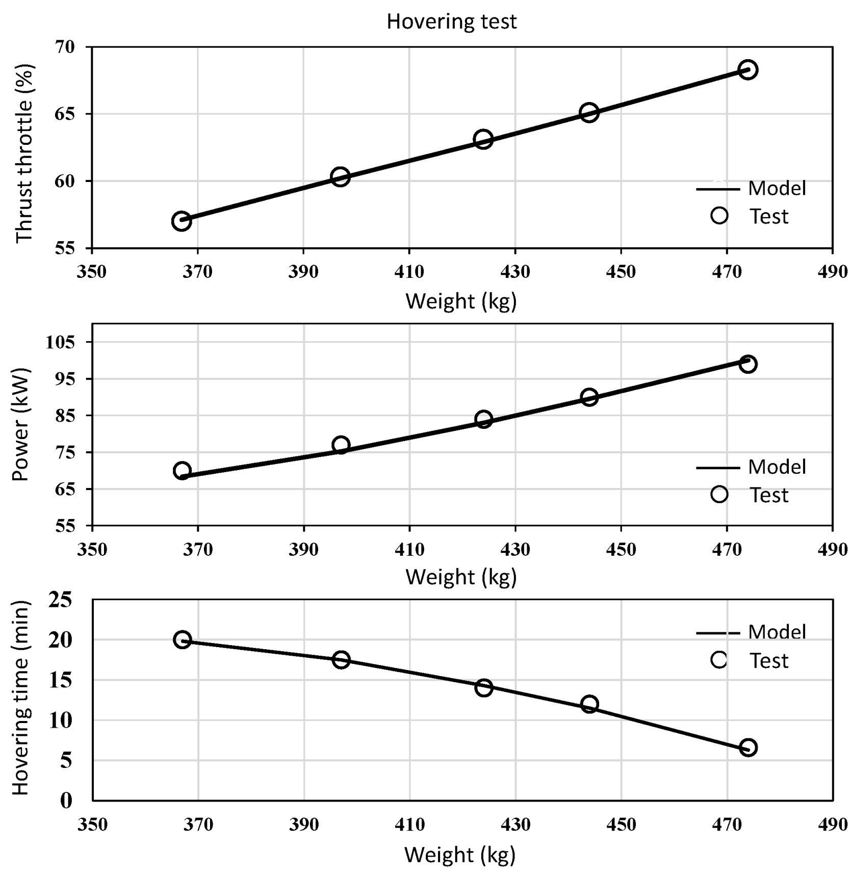
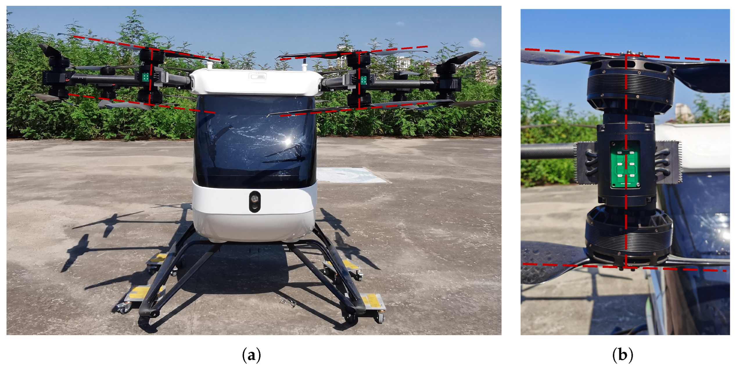
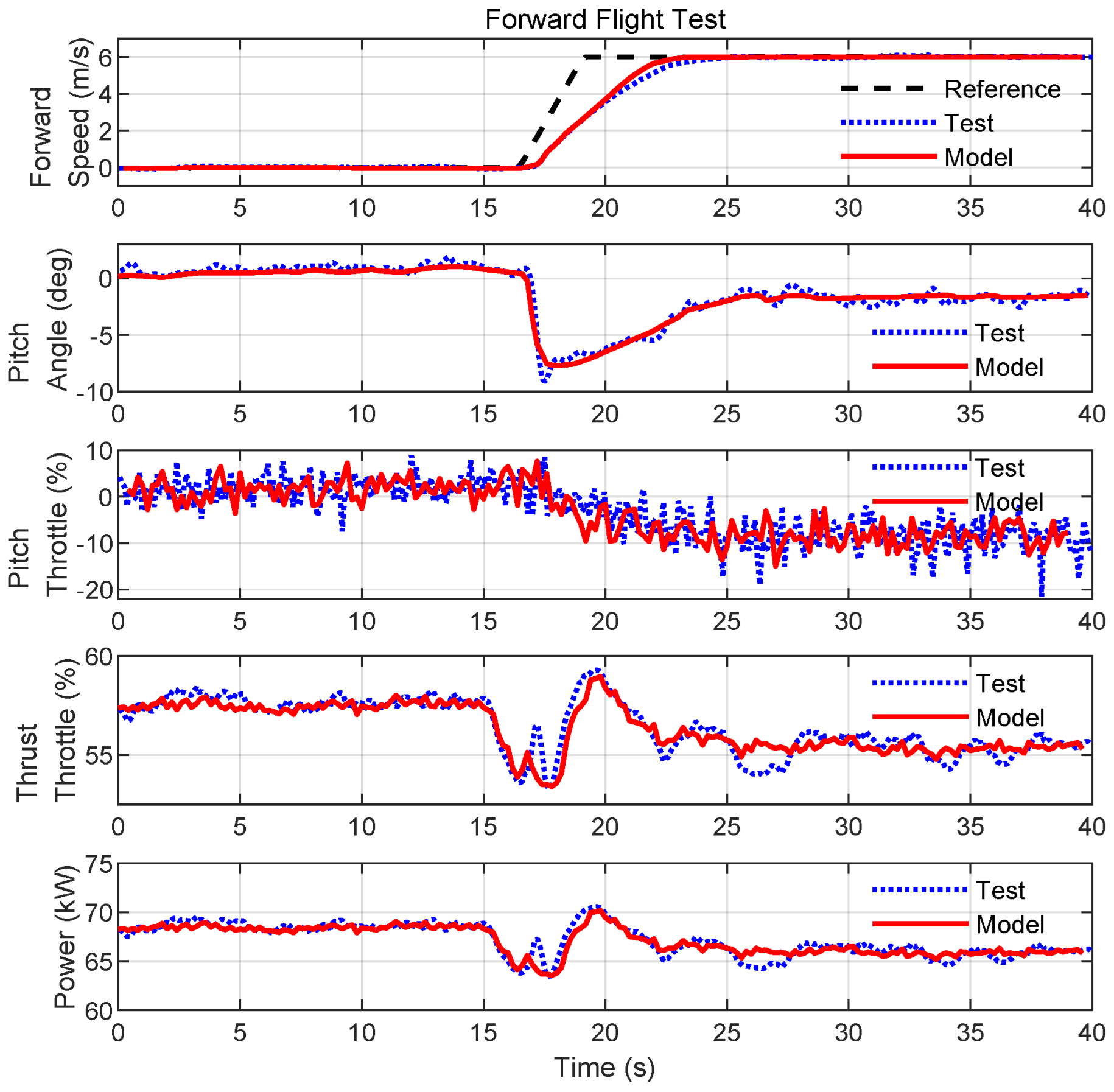
4.1.2. Multirotor Tests

The hovering tests for the initial verification of the dynamics of the overall system are shown in Figure 11, including the hovering throttle, hovering power, and hovering time under different total weights. The experimental result and simulation result are well matched, indicating that the dynamics of the overall system is accurate in the hovering equilibrium state.
Moreover, to further verify the dynamics of the overall system, forward flight tests were conducted, with the multirotor platform shown in Figure 6. For these tests, for which the results are shown in Figure 12 and Table 1, only the forward flight speed, pitch angle, thrust throttle, and pitch throttle are presented, since they strongly contribute to the forward flight scenario. Figure 12 shows the forward speed curves for 6 m/s in detail, in which the transient and steady state are both highly consistent between the experiment and simulation, verifying the high accuracy of the mathematical model established in Section 2. Note that since most of the power is used to compensate for gravity, consumption for horizontal movement is very limited, which is why the shape of the power curve and that of the thrust throttle curve are almost the same. In addition, more results for different forward speeds and different total weights are presented in Table 1.

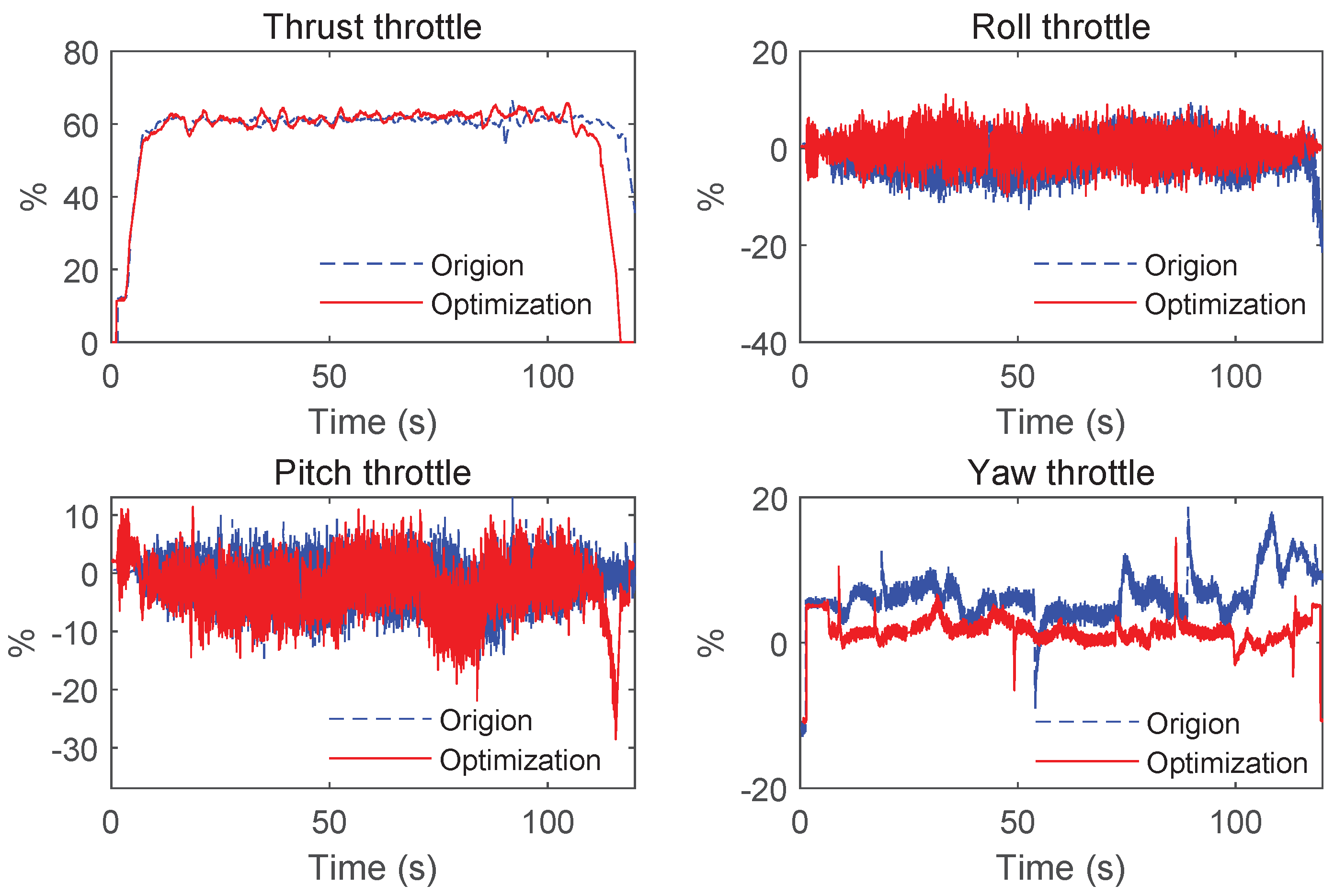
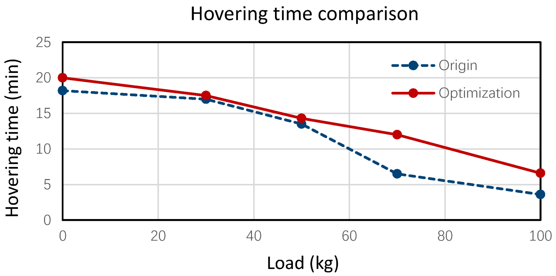
4.2. Design Verification

With a mathematical model of sufficient accuracy, the simulation platform can be used in the design of the rotor tilt angles, and the design results are further experimentally verified on real multirotors.

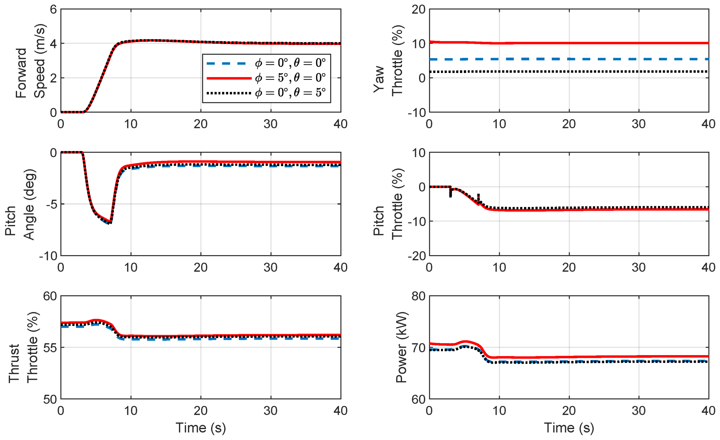
4.2.1. Preliminary Design in Simulation

First, the established high-accuracy simulation platform shown in Figure 7 was used to explore the effects of the dihedral angle and cant angle on the flight performance of large-sized multirotors. The performance variations under medium and high flight speeds were verified, as shown in Figure 13 and Figure 14, respectively.
Figure 13 shows that when the dihedral angle ϕ = 5 , the forward flight speed tracking remains consistent. While the pitch angle decreases slightly, changes in thrust and pitch throttle are minimal. However, the increased yaw throttle leads to higher overall power, compromising the yaw control at lower and medium speeds. In contrast, the configuration with a cant angle θ = 5 significantly reduces the yaw throttle, improving the yaw control without majorly affecting other control channels. Figure 14 shows that the configuration with a dihedral angle ϕ = 5 results in a further decrease in pitch angle without notably affecting other control channels. The yaw throttle increases, but it is slightly better compared to the medium-speed conditions. With a cant angle θ = 5 , the yaw control improves notably at higher speeds, with minor reductions in pitch throttle.
In summary, a dihedral angle design offers the advantage of a reduced pitch angle with minimal changes in thrust and pitch throttle, but it has a pronounced adverse effect on yaw control. On the other hand, a cant angle design significantly reduces the yaw throttle without affecting other control channels.

4.2.2. Offline Design Optimization

Based on the analysis in the previous Section 4.2.1, a dihedral angle only has advantages when flying at high speeds, and it has certain side effects for medium-speed scenarios where large-sized multirotors are restricted. Although the proposed method can theoretically optimize the dihedral angle and the cant angle simultaneously, considering the side effects of the dihedral angle and the convenience of experimental verification, the optimization efforts were concentrated on the design of the cant angle for manned multirotors as an example. Furthermore, the initial installation error of the rotor was also taken into account. Two typical such errors are 0 . 6 and 1 .
Based on the proposed design method and the simulation platform, Table 2 presents the design results with the deference load and forward flight speed. In the Table 2, the throttle variation is the difference between the throttle value after optimization and before optimization. From the throttle variation, the proposed design increases the overall throttle margin by reducing the yaw throttle, thereby making more aggressive flight possible, i.e., improving the maneuverability. For the manned multirotor example, the cant angle for the rotor can be chosen to be 5 , which would be suitable for most situations.
Remark 4. 
It is impossible to design optimal rotor tilt angles for all flight conditions. Generally, some typical flight conditions are selected for design, and their average design is adopted. As a consequence, this average design is suboptimal for some flight conditions, but it is sufficient to improve the overall maneuverability.

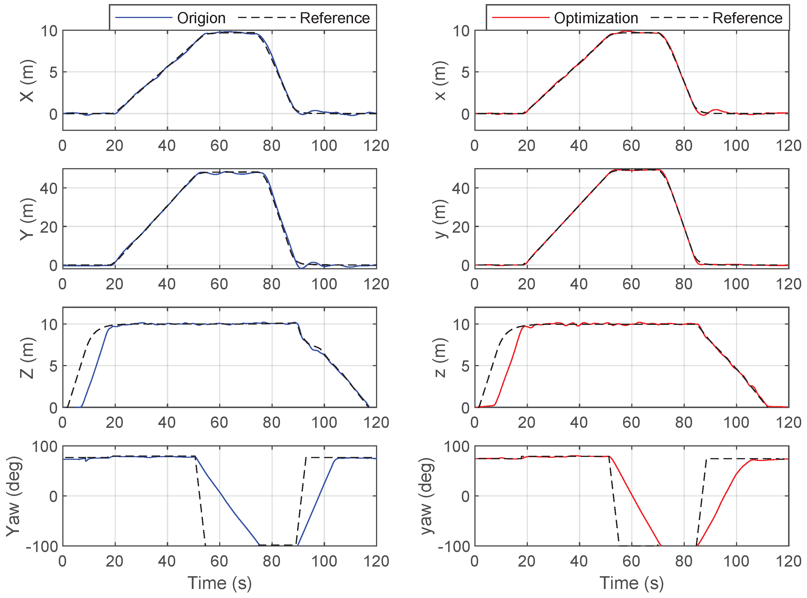
4.2.3. Experimental Design Verification

To verify the effectiveness of the design, trajectory tracking experiments were conducted using the multirotor with eight rotor arms and sixteen propellers, as shown in Figure 6. The 0 dihedral and cant angle of the rotors were set as the original baseline configuration for comparison, as this is the basic design of most multirotors, while the optimized configuration adopted a 5 cant angle for the rotors, as was designed above and is shown in Figure 15. Since the yaw torque generated by the actuator was limited, in order to prevent safety issues caused by actuator saturation, especially for the non-optimized baseline, the maximum yaw angular velocity was limited to 10 /s.
The state comparison results and throttle comparison results are presented in Figure 16 and Figure 17, respectively. It can be observed from Figure 16 that when tracking the same trajectory, the tracking performance of the position was almost the same, while the transient response of the yaw was 4 s faster. Correspondingly, it can be observed from Figure 17 that the yaw throttle value was reduced by an average of 6%, while the throttle values of other channels were almost the same.
In addition to improving maneuverability, the rotor tilt angle design can also improve the battery endurance of multirotors. The hovering experiment was carried out under loads of different weights, and the hovering time was recorded and is shown in Figure 18. It can be concluded that the heavier the load, the greater the relative improvement in the hovering time. Combined with Figure 17, it can be explained that with almost the same thrust, roll, and pitch throttle, the optimized design requires less yaw throttle, so the overall required energy consumption is reduced and the battery endurance time is longer.

5. Conclusions

In this study, an accurate dynamics model for large-sized multirotors was established, and the two-loop optimization method for the rotor tilt angle design of large-sized multirotors was introduced.
More specifically, a high-accuracy dynamics model was established, including aerodynamics, CoG offset, and actuator dynamics. These factors are important for large-sized multirotors, but are normally neglected in small-sized ones. The established model was verified step by step experimentally, starting from a single-rotor system to a coaxial rotor system and finally to an entire multirotor system. All results showed that the measured data and model predictions were highly consistent.
The proposed two-loop optimization method was then based on the established high-accuracy dynamic model. In this case, complex aerodynamic constraints were also introduced into the optimization problem. In order to solve it effectively, the inner loop was designed to solve the equilibrium points of the dynamics. Moreover, this inner loop can achieve the relaxation of the complex aerodynamic constraints in the overall optimization problem.
Benefiting from the experimentally validated high-accuracy models and the well-designed optimization method, the ideal design of the rotor tilt angle was obtained through an offline process, which greatly reduces the difficulties of physical trial and error. It was also verified through experiments that the design results can improve the endurance and maneuverability of large-sized multirotors.
In addition, the proposed method can also be extended to other design tasks. Future work will focus on the design of high-performance controllers to improve fault tolerance and safety.

Author Contributions

Conceptualization, A.X. and W.L.; methodology, A.X., X.Y. and W.L.; validation, A.X. and X.Y.; resources, X.Y. and S.Z.; writing—original draft preparation, A.X., X.Y. and W.L.; writing—review and editing, W.L.; supervision, S.Z. and Z.C. All authors have read and agreed to the published version of the manuscript.

Funding

This work was supported in part by the Key Research Project of Zhejiang Lab (No. K2023NB0AC14), the National Natural Science Foundation of China (No. NSFC-12202406), and the National Natural Science Foundation of China (No. U21A20488).

Data Availability Statement

Restrictions apply to the availability of these data. The data presented in this study can be requested from the first author, Anhuan Xie, with the permission of Zhejiang Laboratory. The data are not publicly available due to commercial confidentiality.

Conflicts of Interest

The authors declare no conflict of interest. The funders had no role in the design of the study; in the collection, analyses, or interpretation of the data; in the writing of the manuscript; or in the decision to publish the results.

References

  1. Coluccia, A.; Parisi, G.; Fascista, A. Detection and classification of multirotor drones in radar sensor networks: A review. Sensors 2020, 20, 4172. [Google Scholar] [CrossRef]
  2. Yao, W.; Chen, Y.; Fu, J.; Qu, D.; Wu, C.; Liu, J.; Sun, G.; Xin, L. Evolutionary utility prediction matrix-based mission planning for unmanned aerial vehicles in complex urban environments. IEEE Trans. Intell. Veh. 2022, 8, 1068–1080. [Google Scholar] [CrossRef]
  3. Rodríguez Marco, J.E.; Sánchez Rubio, M.; Martínez Herráiz, J.J.; González Armengod, R.; Del Pino, J.C.P. Contributions to Image Transmission in Icing Conditions on Unmanned Aerial Vehicles. Drones 2023, 7, 571. [Google Scholar] [CrossRef]
  4. Villa, D.K.; Brandao, A.S.; Sarcinelli-Filho, M. A survey on load transportation using multirotor UAVs. J. Intell. Robot. Syst. 2020, 98, 267–296. [Google Scholar] [CrossRef]
  5. Kotarski, D.; Piljek, P.; Kasać, J. Design considerations for autonomous cargo transportation multirotor UAVs. In Self-Driving Vehicles and Enabling Technologies; IntechOpen: London, UK, 2020. [Google Scholar]
  6. Day, D. Advancing Aerial Mobility: A National Blueprint; National Academies Press: Washington, DC, USA, 2021. [Google Scholar]
  7. Ploetner, K.; Al Haddad, C.; Antoniou, C.; Frank, F.; Fu, M.; Kabel, S.; Llorca, C.; Moeckel, R.; Moreno, A.; Pukhova, A.; et al. Long-term application potential of urban air mobility complementing public transport: An upper Bavaria example. CEAS Aeronaut. J. 2020, 11, 991–1007. [Google Scholar] [CrossRef]
  8. Hamilton, B.A. Urban air mobility market study. In Presentation to NASA Aeronautics Research Mission Directorate; NASA: Washington, DC, USA, 2018. [Google Scholar]
  9. Rashad, R.; Goerres, J.; Aarts, R.; Engelen, J.B.; Stramigioli, S. Fully actuated multirotor UAVs: A literature review. IEEE Robot. Autom. Mag. 2020, 27, 97–107. [Google Scholar] [CrossRef]
  10. Tadokoro, Y.; Ibuki, T.; Sampei, M. Maneuverability analysis of a fully-actuated hexrotor UAV considering tilt angles and arrangement of rotors. IFAC-PapersOnLine 2017, 50, 8981–8986. [Google Scholar] [CrossRef]
  11. de Angelis, E.L. Stability analysis of a multirotor vehicle hovering condition. Aerosp. Sci. Technol. 2018, 72, 248–255. [Google Scholar] [CrossRef]
  12. Mehmood, H.; Nakamura, T.; Johnson, E.N. A maneuverability analysis of a novel hexarotor UAV concept. In Proceedings of the 2016 International Conference on Unmanned Aircraft Systems (ICUAS), Arlington, VA, USA, 7–10 June 2016; pp. 437–446. [Google Scholar]
  13. Bershadsky, D.; Haviland, S.; Johnson, E.N. Electric multirotor UAV propulsion system sizing for performance prediction and design optimization. In Proceedings of the 57th AIAA/ASCE/AHS/ASC Structures, Structural Dynamics, and Materials Conference, San Diego, CA, USA, 4–8 January 2016; p. 0581. [Google Scholar]
  14. Biczyski, M.; Sehab, R.; Whidborne, J.F.; Krebs, G.; Luk, P. Multirotor sizing methodology with flight time estimation. J. Adv. Transp. 2020, 2020, 9689604. [Google Scholar] [CrossRef]
  15. Dai, X.; Quan, Q.; Ren, J.; Cai, K.Y. An analytical design-optimization method for electric propulsion systems of multicopter UAVs with desired hovering endurance. IEEE/ASME Trans. Mechatron. 2019, 24, 228–239. [Google Scholar] [CrossRef]
  16. Liscouët, J.; Pollet, F.; Jézégou, J.; Budinger, M.; Delbecq, S.; Moschetta, J.M. A methodology to integrate reliability into the conceptual design of safety-critical multirotor unmanned aerial vehicles. Aerosp. Sci. Technol. 2022, 127, 107681. [Google Scholar] [CrossRef]
  17. Dai, X.; Quan, Q.; Cai, K.Y. Design Automation and Optimization Methodology for Electric Multicopter Unmanned Aerial Robots. IEEE Trans. Autom. Sci. Eng. 2021, 19, 2354–2368. [Google Scholar] [CrossRef]
  18. Jiang, G.; Voyles, R.; Sebesta, K.; Greiner, H. Estimation and optimization of fully-actuated multirotor platform with nonparallel actuation mechanism. In Proceedings of the 2017 IEEE/RSJ International Conference on Intelligent Robots and Systems (IROS), Vancouver, BC, Canada, 24–28 September 2017; pp. 6843–6848. [Google Scholar]
  19. Franz, H.; Michael, T. System Design for Uncertainty; Massachusetts Institute of Technology: Cambridge, MA, USA, 2010; Chapter 10; pp. 73–82. [Google Scholar]
  20. Ding, C.; Wang, C.; Lu, L.; Ouyang, B. Modeling and control of fully actuated vector thrust unmanned aerial vehicles. In Proceedings of the International Symposium on Flexible Automation 2018 International Symposium on Flexible Automation; The Institute of Systems, Control and Information Engineers: Kanazawa, Japan, 2018; pp. 451–458. [Google Scholar]
  21. Phang, S.K.; Li, K.; Wang, F.; Chen, B.M.; Lee, T.H. Explicit model identification and control of a micro aerial vehicle. In Proceedings of the 2014 International Conference on Unmanned Aircraft Systems (ICUAS), Orlando, FL, USA, 27–30 May 2014; pp. 1048–1054. [Google Scholar]
  22. Bouabdallah, S.; Siegwart, R. Backstepping and sliding-mode techniques applied to an indoor micro quadrotor. In Proceedings of the 2005 IEEE International Conference on Robotics and Automation, Barcelona, Spain, 18–22 April 2005; pp. 2247–2252. [Google Scholar]
  23. Sun, S.; de Visser, C.C.; Chu, Q. Quadrotor gray-box model identification from high-speed flight data. J. Aircr. 2019, 56, 645–661. [Google Scholar] [CrossRef]
  24. Lei, Y.; Cheng, M. Aerodynamic performance of a Hex-rotor unmanned aerial vehicle with different rotor spacing. Meas. Control 2020, 53, 711–718. [Google Scholar] [CrossRef]
  25. Yao, L.; Cheng, M. Aerodynamic performance of hex-rotor UAV considering the horizontal airflow. Appl. Sci. 2019, 9, 4797. [Google Scholar]
  26. Abbaraju, P.; Ma, X. Aerodynamic Modeling of Fully-Actuated Multirotor UAVs with Nonparallel Actuators. In Proceedings of the 2021 IEEE/RSJ International Conference on Intelligent Robots and Systems (IROS), Las Vegas, NV, USA, 24 October 2020–24 January 2021; pp. 9639–9645. [Google Scholar]
  27. Ji, H.; Chen, R.; Li, P. Rotor-state feedback control design to improve helicopter turbulence alleviation in hover. Proc. Inst. Mech. Eng. Part G J. Aerosp. Eng. 2018, 232, 156–168. [Google Scholar] [CrossRef]
  28. Ji, H.; Chen, R. Real-time simulation model for helicopter flight task analysis in turbulent atmospheric environment. Aerosp. Sci. Technol. 2019, 92, 289–299. [Google Scholar] [CrossRef]
  29. Yuan, Y.; Thomson, D.; Chen, R. Investigation of lift offset on flight dynamics characteristics for coaxial compound helicopters. J. Aircr. 2019, 56, 2210–2222. [Google Scholar] [CrossRef]
  30. Ferguson, K.; Thomson, D. Flight dynamics investigation of compound helicopter configurations. J. Aircr. 2015, 52, 156–167. [Google Scholar] [CrossRef]
  31. Ferguson, K.M. Towards a Better Understanding of the Flight Mechanics of Compound Helicopter Configurations. Ph.D. Thesis, University of Glasgow, Glasgow, UK, 2015. [Google Scholar]
  32. Meier, L.; Honegger, D.; Pollefeys, M. PX4: A node-based multithreaded open source robotics framework for deeply embedded platforms. In Proceedings of the 2015 IEEE International Conference on Robotics and Automation (ICRA), Seattle, WA, USA, 26–30 May 2015; pp. 6235–6240. [Google Scholar]
  33. Lee, T.; Leok, M.; McClamroch, N.H. Geometric tracking control of a quadrotor UAV on SE (3). In Proceedings of the 49th IEEE Conference on Decision and Control (CDC), Atlanta, GA, USA, 15–17 December 2010; pp. 5420–5425. [Google Scholar]
  34. Gill, P.E.; Murray, W.; Saunders, M.A. SNOPT: An SQP algorithm for large-scale constrained optimization. SIAM Rev. 2005, 47, 99–131. [Google Scholar] [CrossRef]
Figure 1. Coordinate systems for multirotors.
Drones 07 00614 g001
Figure 2. Equivalent torsion spring approximation, in which e ¯ is the dimensionless hinge offset; W is the flapping amplitude at 0.75 R ; and W t i p is the flapping amplitude at the tip.
Drones 07 00614 g002
Figure 3. Two DoFs of rotor tilt angles and their force analysis. (a) Side view: dihedral angle ϕ . (b) Top view: cant angle θ .
Drones 07 00614 g003
Figure 4. Common control architecture for multirotors.
Drones 07 00614 g004
Figure 5. Two-loop solution of optimization problem for rotor tilt angle design.
Drones 07 00614 g005
Figure 6. Coaxial multirotor with eight rotor arms and sixteen propellers, trajectory tracking.
Drones 07 00614 g006
Figure 7. Simulation platform for multirotors.
Drones 07 00614 g007
Figure 8. Actuator test bench. (a) Configuration of single-rotor test bench. (b) Coaxial rotor test bench.
Drones 07 00614 g008
Figure 9. Tests for aerodynamics of single rotor.
Drones 07 00614 g009
Figure 10. Tests for aerodynamics of coaxial rotor.
Drones 07 00614 g010
Figure 11. Hovering tests for dynamics of overall system.
Drones 07 00614 g011
Figure 12. Forward flight test for dynamics of overall system.
Drones 07 00614 g012
Figure 13. Medium-speed forward flight simulation: maximum speed v m a x = 4 m/s.
Drones 07 00614 g013
Figure 14. High-speed forward flight simulation: maximum speed v m a x = 8 m/s.
Drones 07 00614 g014
Figure 15. Optimized design with 5 cant angle of rotors. (a) Overview; (b) zoomed-in view.
Drones 07 00614 g015
Figure 16. Trajectory tracking experiment: state comparison.
Drones 07 00614 g016
Figure 17. Trajectory tracking experiment: throttle comparison.
Drones 07 00614 g017
Figure 18. Hovering time comparison.
Drones 07 00614 g018
Table 1. Forward flight tests, with different forward speeds and total weights.
WeightForward
Speed
Thrust ThrottlePitch ThrottlePitch AnglePower
TestModelTestModelTestModelTestModel
374 kg 6 m / s 57 % 56 % 10 % 10 % 2.5 ° 2 ° 66.2 kW 64.7 kW
374 kg 10 m / s 53 % 52 % 16 % 17 % 4.5 ° 4 ° 58.3 kW 59.1 kW
374 kg 12 m / s 50 % 50 % 17 % 20 % 7 ° 6 ° 56.2 kW 57.4 kW
429 kg 6 m / s 60 % 61 % 9 % 10 % 2.2 ° 1.9 ° 81.6 kW 80.0 kW
Table 2. Cant angle design results.
Initial
Error
LoadCoGForward
Speed
Cant
Angle
Throttle Variation *
ThrustPitchRollYaw
0.6 ° 0 kg ( 0 , 0 , 0 ) cm 0 m / s 3.44 ° 0.3 % 0 % 0 % 5.6 %
5 m / s 3.78 ° 0.37 % 0.21 % 0.09 % 5.95 %
50 kg ( 5 , 0 , 28 ) cm 0 m / s 3.99 ° 0.19 % 0 % 0 % 6.64 %
5 m / s 4.25 ° 0.26 % 0.26 % 0.08 % 6.89 %
1 ° 0 kg ( 0 , 0 , 0 ) cm 0 m / s 4.92 ° 0.16 % 0 % 0 % 11.02 %
5 m / s 5.46 ° 1.03 % 0.97 % 0.2 % 11.71 %
50 kg ( 5 , 0 , 28 ) cm 0 m / s 5.66 ° 0.36 % 0 % 0 % 13.06 %
5 m / s 6.02 ° 0.56 % 1.28 % 0.19 % 13.55 %
* The difference in the throttle value after and before optimization.
Disclaimer/Publisher’s Note: The statements, opinions and data contained in all publications are solely those of the individual author(s) and contributor(s) and not of MDPI and/or the editor(s). MDPI and/or the editor(s) disclaim responsibility for any injury to people or property resulting from any ideas, methods, instructions or products referred to in the content.

