1. Introduction
In recent years, unmanned aerial vehicles (UAVs) have been widely used in military and civil fields, such as in tracking [
1], surveillance [
2], delivery [
3], and communication [
4]. Due to the inherent defects, such as fewer platform functions and a light payload, it is difficult for a single UAV to perform diversified tasks in complex environments [
5]. The cooperative formation composed of multiple UAVs can effectively compensate for the lack of performance and has many advantages in performing combat tasks. Thus, the formation control of UAVs has become a hot topic and attracted much attention [
6,
7].
Traditional solutions are usually based on accurate models of the platform and disturbance, such as model predictive control [
8] and consistency theory [
9]. This paper [
10] proposed a group-based hierarchical flocking control approach, which did not need the global information of the UAV swarms. The study in [
11] researched the mission-oriented miniature fixed-wing UAV flocking problem and proposed an architecture that decomposes the complex problem; it was the first work that successfully integrated the formation flight, target recognition, and tracking missions into simply an architecture. However, due to the influence of environmental disruption, these methods are difficult to accurately model [
12]. This seriously limits the application scope of traditional analysis methods. Therefore, with the emergence of machine learning (ML), the reinforcement learning (RL) [
13,
14] method to solve the above problem has received increasing attention [
15]. RL applies to decision-making control problems in unknown environments and has achieved successful applications in the robotics field [
16,
17,
18].
At present, some works have integrated RL into the formation coordination control problem solution and preliminarily verified the feasibility and effectiveness in the simulation environment. Most existing schemes use the particle agent model for the rotary-wing UAV. The researchers [
19] first researched RL in coordinated control, and applied the Q-learning algorithm and potential field force method to learn the aggregation strategy. After that, ref. [
20] proposed a multi-agent self-organizing system based on a Q-learning algorithm. Ref. [
21] investigates second-order multi-agent flocking systems and proposed a single critic reinforcement learning approach. The study in [
22] proposes a UAV formation coordination control method based on the Deep Deterministic Policy Gradient algorithm, which enabled UAVs to perform navigation tasks in a completely decentralized manner in a large-scale complex environment.
Different from rotary-wing UAVs, the formation coordination control of fixed-wing UAVs is more complex and more vulnerable to environmental disturbance; therefore, different control strategies are required [
23]. The Dyna-Q(
) and Q-flocking algorithm are proposed [
24,
25] for solving the discrete state & action space fixed-wing UAV flocking problem under complex noise environments with deep reinforcement learning. To deal with the continuous space, ref. [
26,
27] proposed a fixed-wing UAV flocking method in continuous spaces based on deep RL with the actor–critic model. The learned policy can be directly transferred to the semi-physical simulation. Ref. [
28] focused on the nonlinear attitude control problem and devised a proof-of-concept controller using proximal policy optimization.
However, the above methods also assume that UAVs fly with different attitudes, so the interaction (collision) between the followers can be ignored, and the followers in the above methods are seen as independent. Under the independent condition, these single-agent reinforcement learning algorithms can be effective due to the stationary environment [
29]. However, in real tasks, even when the attitude is different, the collision still may happen when the attitude difference is not significant, and the UAVs adjust their roll angles.
In real tasks, the followers can interact with each other, and it is also common for them to collide in some scenarios, such as the identical attitude flocking task. However, this scenario is rarely studied. Ref. [
30] proposed a collision-free multi-agent flocking approach MA2D3QN by using the local situation map to generate the collision risk map. The experimental results demonstrate that it can reduce the collision rate. The followers’ reward function in MA2D3QN is only related to the leader and itself; however, other followers can also provide some information. This indicates that the method did not fully consider the interaction between the followers.
However, MA2D3QN did not demonstrate the ability to manage the non-stationary multi-agent environment [
29], and the experiments also show collision judgments with high computation. With the number of UAVs rising, the computation time also increases. Furthermore, some problems in the above methods on fixed-wing UAVs have not been adequately solved, such as the generalization aspect and communication protocol; the most concerning problem is the minimum cost of the formation.
To consider the communication protocol of the formation, this paper takes the maximum communication distance between the UAVs into consideration, with a minimum cost communication protocol to guide the UAVs to send the message in the formation-keeping process. Under this protocol, the centralized training method for the UAVs is designed; only the leader needs to equip the intelligence chip. The main contributions of this work are as follows:
Research the formation keeping task with continuous space through reinforcement learning, and building the RL formation-keeping environment with OpenAI gym, and constructing the reward function for the task.
Design the communication protocol for the UAVs’ formation with one leader who can make decisions intelligently and five followers who receive the decisions from the leader. The protocol is feasible even when the UAVs are far away from each other. Under this protocol, the followers and leader can communicate at a low cost.
Analyze the PPO-Clip algorithm, give the estimation error bound of its surrogate, and elaborate on the relationship between the bound and hyperparameter : the higher , the more exploration, the larger the bound.
Propose a variation of PPO-clip: PPO-Exp. The PPO-Exp separates the exploration reward and regular reward in the task of formation keeping, and estimates the advantage function from them, respectively. The adaptive mechanism is used to adjust to balance the estimation error bound and exploration. The experiments demonstrate this mechanism with effectiveness for improving performance.
This paper is organized as follows. The first section introduced the current research on UAV flocking.
Section 3 describes the background of the formation-keeping task and introduces reinforcement learning briefly. In
Section 4, the formation-keeping environment is constructed, and the reward of the formation process is designed.
Section 5 discusses the dilemma between the estimation error bound and exploration ability of PPO-Clip, and proposes PPO-Exp to balance the dilemma.
Section 6 shows the experimental setup and results.
Section 7 provides the conclusions of the paper.
2. Related Work
This section reviews current research about fixed-wing UAV flocking and formation-keeping approaches with deep reinforcement learning. According to the training architecture, this paper divides the current methods into the following two categories: centralized and decentralized. The difference between the two categories is as follows:
The centralized methods utilize the leader and all the followers’ states in the training model, and the obtained optimal policy can control all of the followers so that they flock to the leader. The decentralized methods only use one follower and the leader’s state to train the policy, and the obtained optimal policy could only control one follower. If there are several followers in the task, the policy and intelligence chip should be deployed on all of the followers.
2.1. Decentralized Approach
The paper [
24] proposed a reinforcement learning flocking approach Dyna-Q(
) to flock the fixed-wing UAV under the stochastic environment. To learn a model in the complex environment, the authors used Q(
) [
31] and Dyna architecture to train each fixed-wing follower to follow the leader, and combined internal models to deal with the influence of the stochastic environment. In [
25], the authors further proposed Q-Flocking, which is a model-free and variable learning parameter algorithm based on Q-learning. Compared to Dyna-Q(
), Q-Flocking removed the internal models and proved it could also converge to the solutions. For simplification, Q-Flocking and Dyna-Q(
) also require that the state and action spaces are discrete, which is inappropriate. In [
26], the authors first developed a DRL-based approach for the continuous state and action spaces fixed-wing UAV flocking. The proposed method is based on the Continuous Actor-Critic Learning Automation(CACLA) algorithm [
32], with the experience replay technique embedded to improve the training efficiency. Ref. [
33] considered a more complex flocking scenario, where the enemy threat is considered in the dynamic environment. To learn the optimal control policies, the authors use the situation assessment module to transfer the state of UAVs to the situation map stack. Then, the stack is input into the proposed Dueling Double Deep Q-network(D3QN) algorithm to update the policies until convergence. Ref. [
34] proposed the Multi-Agent PPO algorithm to decentralize learning in the two–group fixed-wing UAV swarms dog fight control. To accelerate the learning speed, the classical rewarding scheme is added to the resource baseline, which could reduce the state and action spaces.
The advantage of decentralized methods is that these methods could be deployed on the distribution UAV systems, which could extend to the large-scale UAV formation. The disadvantage of the centralized methods is as follows:
These methods also require all of the followers to be equipped with intelligence chips, which increase the costs.
These methods do not consider the collision and communication problem, due to the use of only local information.
The decentralized approaches also assume that UAVs fly at different heights, and then the collision problem could be ignored. However, in real-world applications, the collision problem must be considered [
30].
2.2. Centralized Approach
Ref. [
35] studied the collision avoidance fixed-wing UAV flocking problem. To manage collision among the UAVs, the authors proposed the PS-CACER algorithm, which receives the global information of UAV swarms through the plug-n-play embedding module. Ref. [
30] proposed a collision-free approach by transferring the global state information to the local situation map and constructing the collision risk function for training. To improve the training efficiency, the reference-point-based action selection technique is proposed to assist the UAVs’ decisions.
The advantages of the centralized methods are as follows:
These methods could reduce the cost of the formation. Under the centralized architecture, the formation system only requires the leader to equip the intelligence chip. The followers only need to send their state information to the leader and receive the feedback commands.
These methods could consider collision avoidance and communication in the formation due to their use of global information.
The disadvantage of the centralized method is the dependence on the leader. Ref. [
36] pointed out that the defect or jamming of the leader causes failure in the whole formation system.
When the number of UAVs increases or the tasks are complex, the centralized methods face the dimension curse and lack of learning ability problems. A popular approach is learning the complex tasks with a hierarchical method [
37,
38], which divides the complex tasks into several sub-tasks and uses the centralized method to optimize the hierarchies. The hierarchical reinforcement learning approaches are applied in the quadrotors swarm system [
37,
38], but are rarely used in fixed-wing UAV systems.
Even when using global information in training, the current centralized approaches fail to consider communication in the formation. Compared to current centralized approaches, the approach proposed in this paper considers the communication in formation, and provides the communication protocol. Through the communication protocol, the formation system could be considered as one leader with an intelligence chip and five followers without intelligence chips; the leader collects the followers’ information, with a centralized train on the intelligence chip. The followers receive the command from the leader through this protocol and execute.
3. Background
This section will introduce the kinematic model of the fixed-wing UAV, restate the formation keeping problem, and briefly introduce reinforcement learning.
3.1. Problem Description
The formation task can be described as follows: At the beginning, the formation is orderly (shown in
Figure 1), which is a common formation designed in [
39]). The goal of the task is to reach the target area (the green circle area) with the formation in as orderly a way as possible; when the leader enters the target area, the mission is complete.
During the task, assume the UAVs are flying at a fixed attitude; then, each UAV in the formation can also be described as a six-degree of freedom (6DoF) dynamic model. However, analyzing the six-degree model directly is very complex; it will increase the space scale and make control more difficult. The 6DoF model can be simplified to the 4DoF model; to compensate for the loss incurred during this simplification, random noise is introduced into the model [
27], and the dynamic equations of
ith UAV in the formation can be written as follows:
where
is the planar position, and
represent the heading and roll angle, respectively, (see
Figure 1). The
is the velocity, and
is the gravity acceleration. The random noise values
are the normal distributions, its means are
, and its variances are
, respectively, (the gray dotted circles in
Figure 1 show the area of influence, of random factors); they represent the random factors introduced by simplification and environment noise.
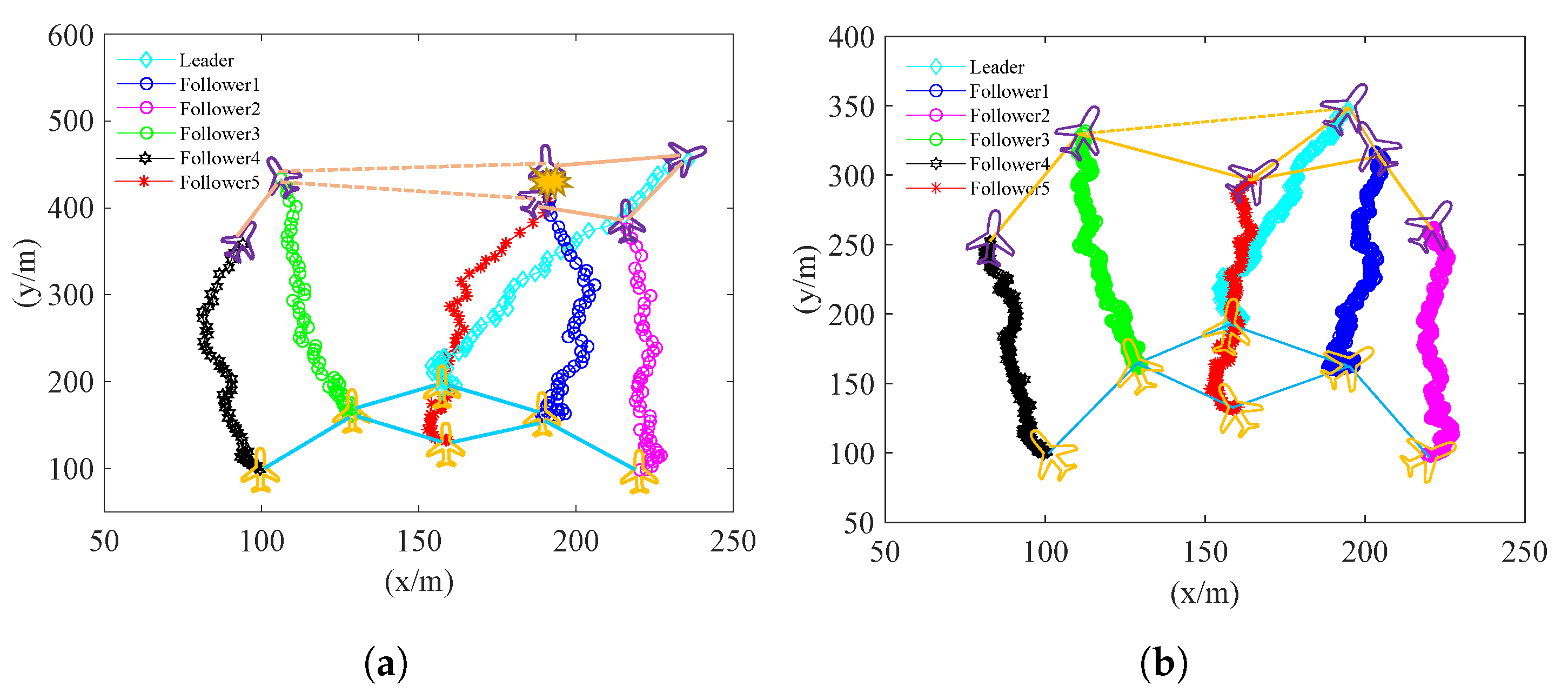
A simple control strategy can make the formation satisfactory when the environment’s noise is low. However, under a strong inference environment, such as one with strong turbulence, the random factors will be apparent, leading the formation to maintain the complexity of the task. If no effective control is provided, the formation will break up quickly, (this is demonstrated in
Figure 2), and a crash may happen.
Furthermore, even though there is an effective control policy for the formation, the coupling between the control and communication protocol can also be an unsolved challenge. Because the communication range of UAVs is limited, if the UAV wants to know others’ states, it has to wait for other UAVs out of range to send state information to UAVs it can communicate with, which in turn send state information to it. If no harmonic protocol is applied in the formation control, the asynchronous and nonstationary elements will be introduced into the formation control, making the control strategy more complex.
3.2. Reinforcement Learning
In the last part, the solution of differential Equation (
1) can be represented as the current dynamic parameters adding the integral items by difference equation methods such as the Runge–Kutta method. So, the UAV formation control can be modeled as a Markov Decision Process(MDP), which refers to the decision process that satisfies the Markov property.
The MDP also can be described as the tuple . represents the state space, represents the action space, and is the transition probability. The reward function is , and is the discount factor, which leads the agent to pay more attention to the current reward.
Reinforcement learning can solve the MDP well to maximize the discounted return, as follows:
. The main approaches of RL are divided into the following three categories: value-based, model-based, and policy-based. The policy-based methods have been developed and widely used in various tasks in recent years. These methods directly optimize the value function by the policy gradient:
where
is the advantage function that is equal to the state-action value function, and the the state value function is subtracted, as follows:
PPO (Proximal Policy Optimization) is one of the most famous policy gradient methods in continuous state and action space [
40]. In policy gradient descent, PPO updates the following equation at each update epoch:
However, using the constant clip coefficient , the PPO also proved its lack of exploration ability and difficulty in convergence. Therefore, designing an efficient dynamic mechanism to adjust and ensure greater exploration and faster convergence is also challenging.
4. Formation Environment
This section constructs the fixed-wing UAV formation-keeping environment, the formation topology, communication and control protocols, and collision. Communication loss is also considered in the environment through the reward design.
4.1. State and Action Spaces
In the course of the formation task, based on the 4DoF Equation (
1), it is modified to a more realistic control environment. For the
ith UAV, assume the thrust of the UAV is controllable, and it will generate a linear acceleration
. Moreover, assume the torque of the roll angle is controllable too, and add the roll angle acceleration
into the dynamic equations. Finally, the dynamic equations of
ith UAV can be modified as follows:
To control the UAVs, linear acceleration and roll angle acceleration are input. For control, we have the dynamic model of
ith UAV:
The state and action spaces for existing methods in UAVs controlled by reinforcement learning are often discrete, but in the real world, the state space is continuous and changes continuously as time goes on. Therefore, combining the analysis of the previous dynamics, we define the state tuple of the
ith UAV as
. The planar position
, heading
, roll angle
, line and angle velocity
are determined by solving the differential Equation (
5).
In the action space, although the engine can produce fixed thrust, the real thrust acting on the UAVs in the nonuniform atmospheric environment is not of the same value as the engine product. So, we define the action space by
. Assume the UAVs can also produce the same acceleration in positive and negative directions, where we have
, and
. The action will influence
through Equation (
6), and then influence the
indirectly.
After defining the individual state and action of the UAV, we define the formation system state and action by sticking to the individual state (action) as a vector. Define the state of system , and the action of system .
4.2. Communication and Control Protocol
To ensure the UAV formation consumes less energy in the information send and receive process, and ensure the reinforcement learning method can be helpful in the task, the communication and control protocol for the UAV formation will be provided in this part.
As is shown in
Figure 1, the formation is of a Leader–Follower structure; in terms of hardware, all the UAVs are equipped with gyroscopes and accelerometers to monitor their action and state parameters. Only the leader has the “brain” chip that can make decisions intelligently; the followers only have the chips that can receive the control command signals, take the command action and send the state signals.
To describe this relationship, the graph model is introduced. Use the communication graph
to describe the communication ability of the formation at time
t [
39]:
where
is the set of nodes that represent UAVs, the
represent the arc set at time
t, e.g.,
denote an arc from node i to node j, which means the UAV
i can communicate with UAV
j directly at time
t. The adjacent matrix
of graph
is used to describe the communicated situation of formation in real-time, e.g., at the initial time, the adjacent matrix is as follows:
The adjacent matrix is symmetric, and its element indicates the communication situation of UAV i and UAV j. If , then , and the ith and jth UAVs can share their state, and the control command can be sent from i to j or j to i. The adjacent matrix is updated in real-time. If the distance between two UAVs is greater than the communication limited distance , the corresponding elements of the adjacent matrix will be 0.
Additionally, at the initial time, the formation is connected, and the connected component
is 1. l If the UAVs want to keep in communication with all the others, the graph
should only have one connected component. In the graph model, this condition could be transferred to
. The methods that judge whether an undirected graph is connected include union-find disjoint sets, DFS, and BFS [
41]. So, after DFS or BFS, the task fails when the connected component number
of graph
is more than 1. When the formation works,
should be 1.
When the formation works, the protocol should be active to support the UAVs communicating with each other. The communication protocol’s primary purpose is to send all the UAVs’ states to the leader for the decision; the control protocol sends the action command to all the UAVs. When the formation is as orderly as it was at first, the information only needs to obey the transfer route (shown in
Figure 1), so the whole formation can be controlled well. However, when the noise disturbs the position of UAVs, it makes the connection between the UAVs that are not connected at the initial time. It breaks the connection between the UAVs that are connected at the initial time. To handle the chaos brought about by the noise, a communication and control protocol is shown in
Figure 3.
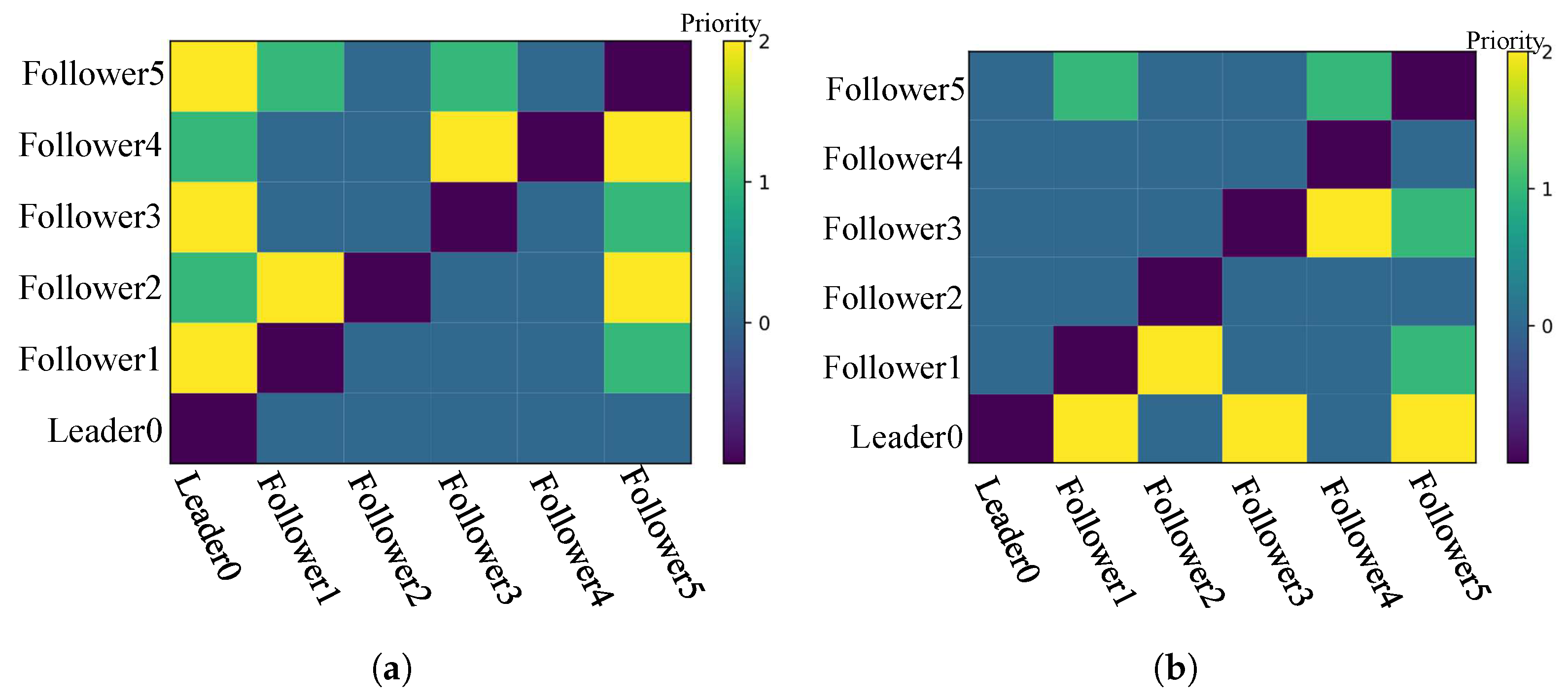
In
Figure 3a the communication protocol is shown, where the block in
ith row represents the communication priority of the corresponding UAV. For the priority, the bigger the number, the higher the priority. Priority 1, 2 determines the order of communication. If the priority is 0, both parties have no communication probability. i.e., when the leader0 and follower3 are within the communication range of follower5, the follower5 will send the information to leader0 instead of follower3.
The protocol is designed based on the communication object: to send all the followers’ state information to the leader to support the decision. So, the principle of the protocol is to give the followers closer to the leader higher priority, such as followers 1, 3 and 5.
Figure 3b has a similar meaning to the control protocol. The target of the control protocol sends the control information to all the UAVs. The control protocol motivates the leader to send the control information to the followers that connects as much as the followers. Therefore, leader0, and follower1, 2, and 5 have priority 2 because they can connect with up to 2 other followers.
4.3. Reward Scheme
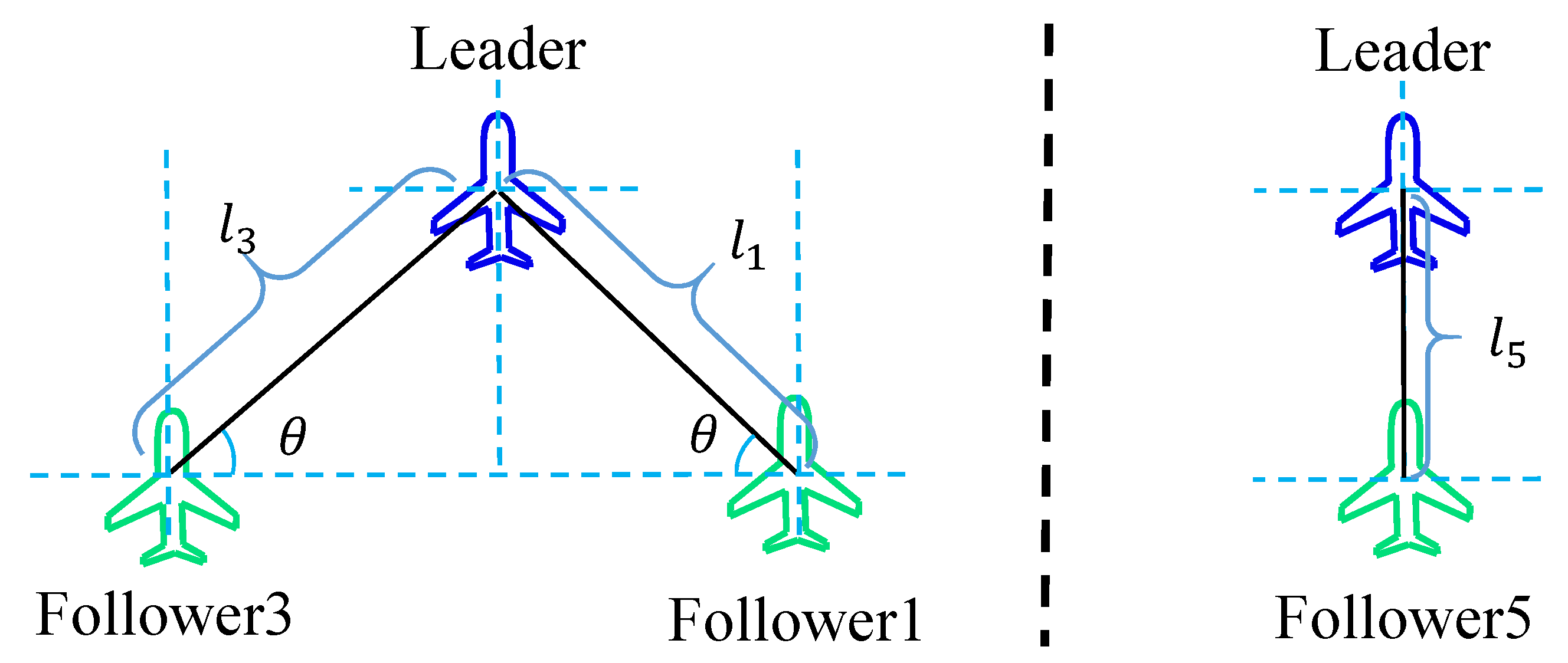
The goal of the formation-keeping task is to reach the target area and ensure the formation is as orderly as possible. At first, the orderliness of the formation is of primary concern. So, some geometric parameters are defined to describe the formation. The followers in the formation can be divided into two categories, one is on an oblique line with the leader, like followers 3 and 4, and another is on a straight line with the leader. Only follower 5 belongs to this category. The linear between the leader and the position where the follower should be located is called the baseline (see the back lines in
Figure 4). Then, it is easy to know the first category followers have a baseline with a slope, and the second follower’s baseline does not. For the follower
i, the length of the initial baseline is
, and the initial slope is
(the first category).
To make sure the UAV agent can return to the position that makes formation more orderly, for
ith UAV, the formation reward is designed as follows:
where
represents the distance between the follower
i and the baseline along the vertical line of the baseline, and
represents the distance between the leader and follower
i along the baseline. The formation reward is
.
When the UAVs belong to the first category follower (e.g., follower 3), the distance
can be calculated by the following formula:
Followers 2 and 4 have the same
as in the above equation. The distance
also can be obtained with the following formula:
For the second category follower (follower 5), it is easy to know that the reward can be represented as the following simple formation:
Furthermore, the main target of UAVs formation is to reach the target area, which is a circle with center coordinates
and radius
. To encourage the formation to reach the target area, a sparse reward is designed as the destination reward:
We only calculate the distance of the leader. Only when the formation reaches the target area do the UAVs receive this sparse reward, and the learning process will halt. It leads to the UAVs not only needing to take minor actions to ensure that the orderly formation is not disorganized by the disturbance, but also needing to adjust direction to reach the target area. From the reward design view, UAV agents need to try different actions to discover and obtain a sparse signal. To accelerate the learning, the exploration rewards, as described in the literature [
42], are designed as the incentive reward:
When the formation is closer to the target area, it will receive a higher exploration reward, leading the UAV agent to learn to reach the target area.
Meanwhile, some UAVs are too close and crash together, or they are too far and cease communicating with each other. In that case, the formation will suffer permanent destruction, and the task will halt.
Setting the minimum distance for crashes makes it easy to obtain the halt condition of UAV crashes. Then, the penalty should be added to avoid the above situation. This penalty is designed as a formal sparse reward as follows:
where the
represents the minimum distance between the
jth UAV and another five UAVs:
. The lowest communication distance is
, once the minimum distance
less than
, the
jth UAV will lose the communication ability with other UAVs. In addition,
is the crash distance; as long as the distance between two UAVs is less than this, the two UAVs might crash.
Finally, the reward of the formation system at time
T can be represented as the sum of the following reward function:
5. PPO-Exp
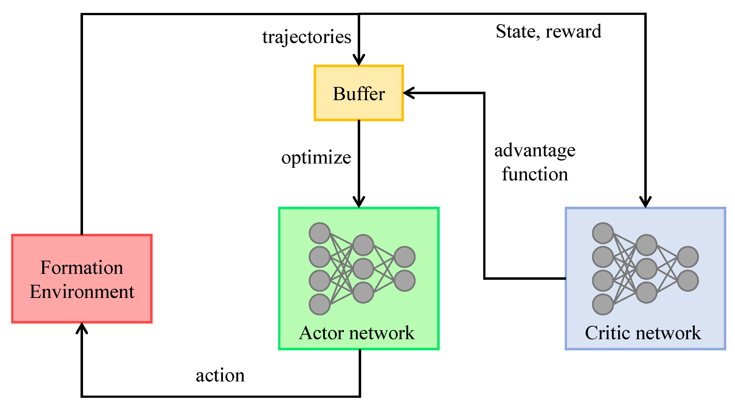
PPO is one of the most popular deep reinforcement learning algorithms in continuous tasks that achieved outstanding performance. The PPO embedded the Actor–Critic algorithm, which uses a deep neural network as an Actor for policy generation, and another deep neural network as a Critic for policy estimating. The structure of PPO can be seen in
Figure 5; the Actor interacts with the environment, collects the trajectories:
and stores them in the buffer, then it uses the buffer and the value function estimated by the Critic to optimize the Actor network’s hyperparameter according to following surrogate:
where the
is the advantage function defined in Equation (
3). The Critic network’s hyperparameter
is updated by minimizing the following MSE error:
The gradient of Equations (
17) and (
18) is computed and used to update the hyperparameters
and
until they converge or reach maximum steps. In surrogate (
17), the PPO restricted the difference between new and old policy by using the clip trick to restrain the ratio
. It could be considered a constraint on updated policy; under it, the ratio should satisfy the following constraint:
. Then, the updated policy is restricted as follows:
The coefficient
is also a constant in the range
in PPO-Clip; from the inequality (
20), it can be seen that the relative deviation is bound between
and
. When this deviation is under
, as the increase in
is observed, the
increase as well, but when the deviation exceeds
, even if the
is increases, the
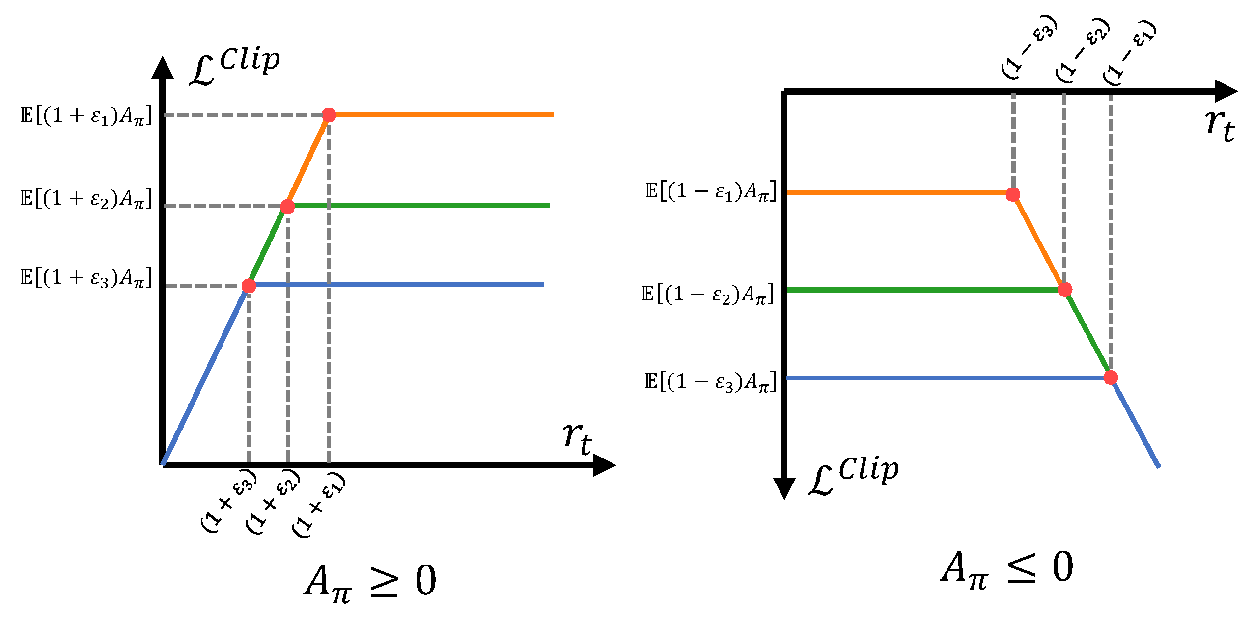
maintains its value. It shows the exploration within the constraint
; however, when the relative difference is beyond
, the exploration is not encouraged by clipping the result to
.
Figure 6 shows the surrogate of PPO-Clip in different
. The large
could encourage the agent to explore more and accept more policies. However, enlarging
will lead to the estimated error of the surrogate. The PPO-Clip is the off-policy algorithm. The data generated by the old policy will be used as new policy updates. When
, the estimated error bound of
will increase as
increases. For convenience, denote the following assumption:
Assumption 1. In the previous t timestep of policy update, the ratio satisfies .
Under Assumption 1, the following Lemma is given for auxiliary proof of the error bound:
Lemma 1. Under Assumption 1, the difference of state distribution resulting from the policy satisfies the following inequality: Proof. The distribution
can be rewritten as [
43]:
where
is the distribution resulting from
at
k timestep. Using the Markov property,
, the
could be decompose as follows:
Using the decomposition, the following equation holds:
Using the triangle inequality, the following equation hold:
Sum up the inequality (
25) to calculate the expectation on
:
Using Equation (
22), the following equation holds:
□
Using this Lemma, the estimation error of the PPO-Clip could be obtained:
Theorem 1. Under the Assumption 1, the estimation error of PPO-Clip is satisfied: Proof. When
, the surrogate of the PPO-Clip will be degraded [
40]:
The above surrogate is the importance sampling estimator of the objective of the new policy [
44]:
However, the estimator uses the data generated by
, and the state distribution of
is derived from
. Therefore, the estimation error is satisfied:
Consider the positive advantage situation and expand the integral of
a; the following equation will hold:
Using the conclusion of Lemma 1, the following error bound could be obtained:
where the
represents the uniform distribution of the state. □
Theorem 1 confirms the positive relationship between the estimation error and . By using it, a more clear conclusion could be obtained:
Remark 1. In PPO-Clip, the high ε could enhance the exploration but will result in a high estimation error bound of the surrogate; the low ε could decrease the error bound but will restrict the exploration.
Therefore, to deal with the exploration and estimation error problems mentioned in Remark 1, this paper considers making the adaptive in different situations. The last part designed the sparse reward , and the exploration reward is designed as the incentive reward. The agent should explore more in the task to receive a high-level and . So, when these rewards are too low, the agent should release the restriction on to encourage the exploration. When these rewards are high and stable, the restriction on increases to ensure the estimation of the surrogate is accurate.
So, the exploration advantage function
can be used to represent the advantage function that is estimated by
and
, which can reflect the exploration ability of the agent:
According to the exploration function, an exploration PPO algorithm is proposed with an adaptive clip parameter
. When the exploration advantage function is lower than last time, to improve the exploration ability,
will be enlarged. Otherwise, the
will be reduced, restraining the updated policy in a trust region. To sum up, the adaptive mechanism is designed as follows:
The clip function in the above equations is to restrict the adaptive mechanism and avoid the
being abnormal. Through the variation of the exploration advantage function, the exploration-based adaptive
mechanism is proposed. When simply replacing the constant
with the adaptive
, the PPO will be PPO-Exploration
(PPO-Exp). With the restriction of old policies, new policies will be adjusted automatically. The surrogate of the PPO-Exp is as follows:
The Algorithm of PPO-Exp in the formation environment could be seen in Algorithm 1. The exploration and estimation error problem in PPO-Exp could be adapted without delay, and the following Proposition will give the exploration range and the estimation error decrease rate in different situations:
| Algorithm 1 PPO-Exploration with formation keeping task. |
Initialize ,. for, N do for do The leader0 collects state information through the communication protocol ( Figure 3a) Run policy , obtain the action , and send them using the control protocol ( Figure 3b). The leader and followers execute the action commands and receive a reward as follows: Store at the buffer. end for Transitions data from buffer, and estimate , , respectively. if then end if if then end if for do Update by SGD or Adam. end for Update critic network parameter by minimizing: end for |
Proposition 1. In PPO-Exp, when , the exploration range of next policy will be expanded to ; when , in next update, the error bound of the surrogate will decrease to .
Proof. When
, according to Equation (
35), it is easy to see the next policy will be expanded to
. Then, the following inequality will hold:
So, the following inequality is held:
When
, and Assumption 1 is satisfied, it is obvious that the conclusion of Theorem 1 could be used in PPO-Exp. So, using Equation (
35) and Theorem 1, the PPO-Exp’s decrease rate of the bound is as follows:
where the
is the upper bound of advantage:
□
Proposition 1 indicates that the PPO-Exp could encourage the agents to adjust the exploration in different situations. The next section will validate it through numerical experiments.
6. Numerical Experiments
This section compares the PPO-Exp with four common reinforcement learning algorithms (PPO-Clip, PPO-KL, TD3, DDPG) in the formation-keeping task, and compared the performace of PPO-Exp and PPO-Clip in the formation changing task and obstacle avoidance task.
6.1. Experimental Setup
In terms of hardware, all the experiments are completed on the Windows 10 (64-bit) operating system, Intel(R) Core i7 processor, 16 GB memory, and 4 GB video memory. As for software, OpenAI-gym [
45] is used to design the reinforcement learning environment and the physics rulers of the UAVs’ formation.
The formation task is modeled on the OpenAI gym environment. See
Figure 1; the position of the leader and followers can be seen in
Table 1. The formation is updated by the dynamic equations solved by the difference method per 0.5 s per time mesh grid. The environment noises are set as
default. The target area is designed as a circle at
with a radius of 40.
6.2. Experiments on PPO-Exploration
The following famous continuous space RL algorithms are explored in this section: TD3, DDPG, PPO-KL, and PPO-clip; they are compared to the proposed method under the formation-keeping task.
PPO-Clip [
40]: Proximal Policy Optimization with Clip(PPO-Clip) function.
PPO-KL [
40]: Proximal Policy Optimization with KL-divergence(PPO-KL) constrain.
DDPG [
46]: Deep Deterministic Policy Gradient(DDPG) algorithm, which is a continuous action deep reinforcement learning algorithm that uses Actor–Critic architecture. In DDPG, the deterministic policy gradient is used to update the Actor parameter.
TD3 [
47]: Twin Delayed Deep Deterministic (TD3) policy gradient algorithm, which is a variant of DDPG. The TD3 introduced the delaying policy updates mechanism and the double network architecture to manage the per-update error and overestimation bias in DDPG.
The main hyperparameters of the contrast experiment are shown in
Table 2. The blank area in the above table means the algorithm does not include this parameter.
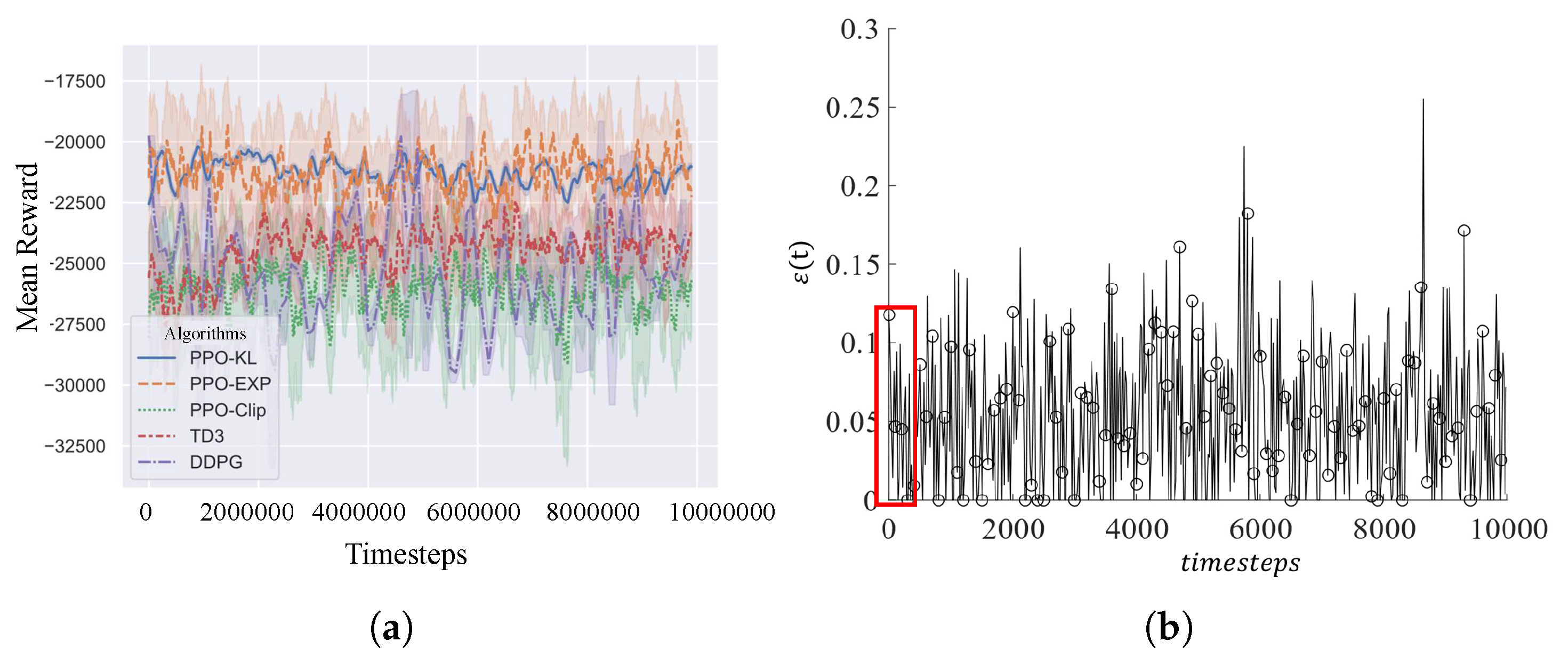
Set the episode length be 200; the results of PPO-Exploration
and other comparing algorithms are shown in
Figure 7a. As the learning curves indicated, the PPO series methods achieved better performance; in all variations of PPO, the PPO-Exp has the best performance. It is validated that the adaptive mechanism based on exploration makes sense during policy updating.
Figure 7b shows the change of
; the series
is stationary, and varies around 0.05, although the initial value is 0.1, which means 0.05 is the balance point between exploration and exploitation found by PPO-Exp. Meanwhile, the episode reward curve of PPO-Exp is higher than PPO-Clip’s, validating the idea that exploration from PPO-Exp is efficient.
6.3. Experiments on Formation Keeping
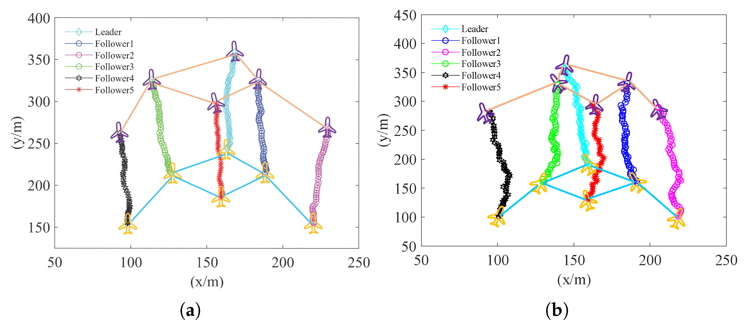
Only the learning curve was unable to declare whether the algorithm works well, so the trained PPO-Exp is used to perform 200s; the formation track can be seen in
Figure 8. In this way, there is only a slight distortion in the formation, indicating that PPO-Exp can perform better in real tasks than PPO-Clip.
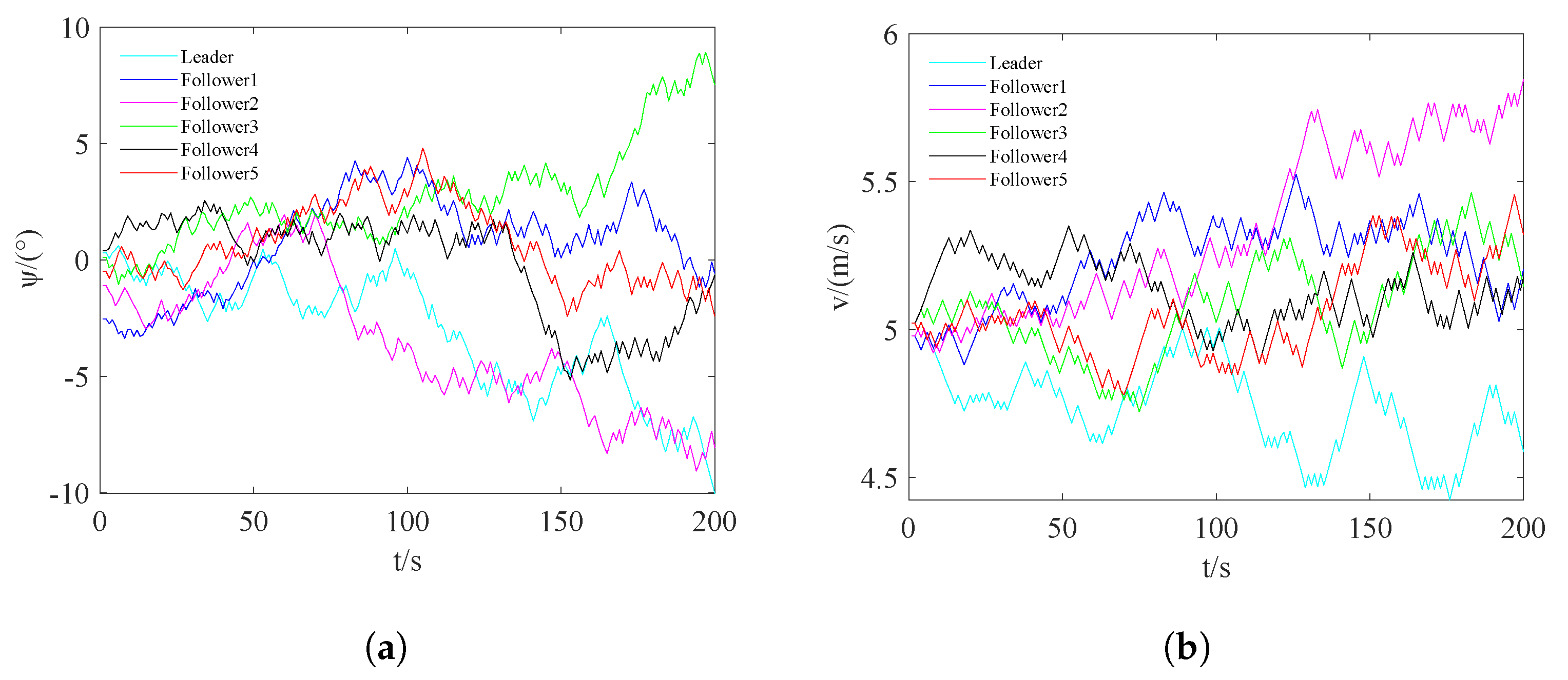
Furthermore, to evaluate the results, we plotted the heading
and the velocity
v during 200 s in
Figure 9.
Figure 9a shows that followers 1, 4, and 5 are approaching gradually as time goes on. Followers 2, 3 and the leader, have no such trend to converge gradually; however, all the heading deviations are no more than
. In
Figure 9b, the velocity of each UAV is shown. The velocities of followers 1, 3, 4, and 5 diverge a little and then converge. Corresponding to
Figure 9a, followers 1, 4, and 5 are closer in terms of the value of velocity and heading; the leader and follower 2 are far away from these followers, but the velocity difference is not more than 1.5 m/s as well. This inspired us to design the reward based on the velocity and heading.
To illustrate the influence of environmental noise on formation keeping, the results show the formation track with no control in
Figure 2a. To verify that the proposed centralized method saves time, this section further compares the decentralized version of PPO-Exp: PPO-Exp-Dec, which, similar to MAPPO, needs all six UAV agents to learn the control policy at the same time.
To validate that the protocol can reduce the communication cost and avoid placing the UAVs out of the communication range, this section also compares the protocol-free version: PPO-exp-pro. The results can be seen in
Table 3.
represents the episode reward,
T represents time per episode,
and
represents the collision rate and failure to communicate rate, respectively.
To further verify the effectiveness of the proposed method, ablation experiments are performed (see
Figure 2a,b and
Figure 8b).
Figure 8b shows the trained PPO-clip without the exploration mechanism. Although there is no UAV crash, the leader and follower3 are very close, and the formation is not as orderly as the PPO-Exp.
Figure 2a shows the result of no action taken, where the UAVs will crash, and the formation will break up.
Figure 2b shows the trained PPO-clip with
, which is the balance point in the PPO-Exp. However, the experimental result shows it performs worse; there is one follower that loses communication with leader, and one follower almost crashes with the leader. The result illustrates that the PPO-Exp with adaptive
is better than the PPO-Clip with a good
. In summary, the ablation experiments also indicated that PPO-Exp performs better than other algorithms in terms of learning curves and the real-task.
6.4. Experiment on More Complex Tasks
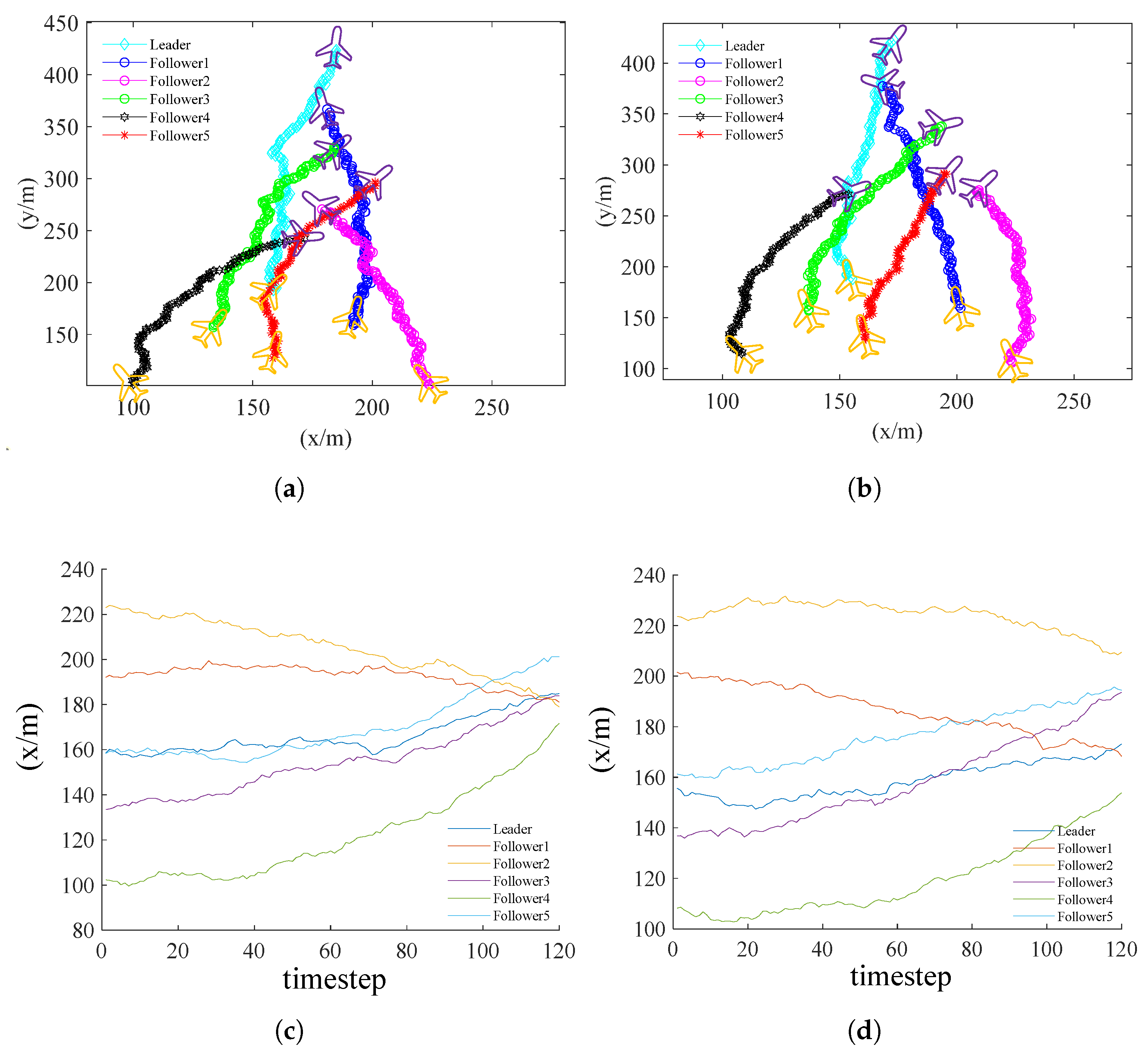
To further show the efficiency of PPO-Exp in fixed-wing UAV formation keeping, this part design two more complex scenarios: formation changing and obstacle avoidance task, the UAV formation perform 120 s on each task. This part mainly compared the performance of PPO-Exp and PPO-Clip on these tasks.
The goal for the formation changing task is changing the formation shown in
Figure 1 to the vertical formation. The vertical formation also expects the differences between leader and followers are as small as possible in coordinates on the x-axis. For guiding the followers to change the formation, this paper utilizes the absolute difference value of
x coordinates to modify the flocking reward. The modified flocking reward (
9) and (
12) could be represented as follows:
Then the total reward (
16) can be rewritten as follows:
where the
represent the
x coordinates of leader and
ith follower at time
T, respectively. To encourage the UAV system to take more exploration on forming new formation, the flocking reward is added to the exploration advantage function:
Training the task with PPO-Exp and PPO-Clip, the training parameters are kept as same as in the previous part except episode length. After training, the test result of PPO-Exp is shown in
Figure 10a, and the PPO-Clip is shown in
Figure 10b. To evaluate the performance, this paper draws the plots of the
x coordinates and timesteps of the leader and followers in
Figure 10c,d. The closer the
x coordinates of followers to that of the leader, the better the performance will be. The
x coordinates of followers in (c) converge to the leader faster than (d), representing that PPO-Exp can change vertical formation faster than PPO-Clip.
To further evaluate the formed vertical formation. Denote the terminal time as
, calculate the average difference between the followers and leader in
x coordinates in the last ten timesteps, and denote the result as
, which can be represented as follows:
The low indicates the follower is close to the leader in x coordinates. In PPO-Clip, the calculated , but in PPO-Exp, the calculated , which is nearly half of the PPO-Clip.
Compared to the control strategy in formation keeping, the followers in formation changing tasks perform good cooperation. All followers maneuver orderly to the position where the leader’s x-coordinate is located. To avoid the UAVs collide each other, the followers decided to move to different positions on the y-axis. The followers take different maneuvers depending on their initial position to reach the position. e.g., follower 4, in the initial time, is far away from the leader in x-coordinates. For follower 4, a collision avoidance path is moving to the tail of the newly formed formation. Therefore, the follower4 achieves a large angle arc maneuver and moves to the tail of the formed vertical formation.
The target of the obstacle avoidance task is to reach the target area and avoid crashing into the obstacle. This paper considers a circle area on the plane as an obstacle. Denote the coordinates of the obstacle center is
, and the radius is
. A simple approach to consider this situation is to add a penalty on the formation system reward when the UAVs crash on the obstacle, the penalty effect. The penalty for crashing into the obstacle is denoted as follows:
Similar to the exploration reward
, to
Then the total reward (
16) can be rewritten as follows:
To encourage the UAV system to take more exploration on avoid obstacle, the exploration reward in avoid obstacle
is added to the exploration advantage function:
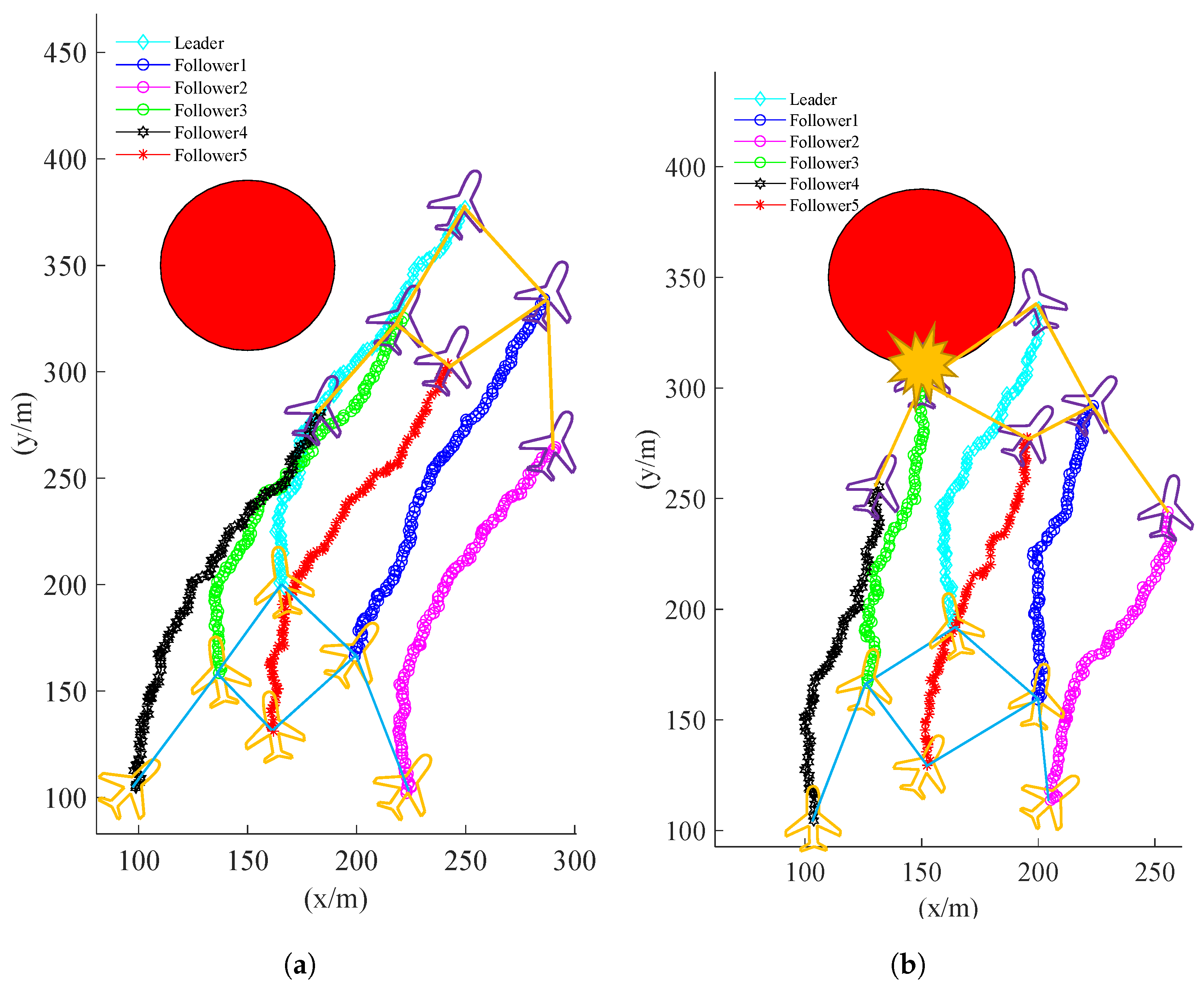
Training the obstacle to avoid task with PPO-Exp and PPO-Clip, the training parameters are kept as same as the previous part except episode length. After training with PPO-Exp and PPO-Clip, the test results of obstacle avoid task are shown in
Figure 11a, and the results of PPO-Clip can be seen in
Figure 11b. A follower in the formation trained by PPO-Clip crashed on the obstacle at 94 timesteps. The formation trained by PPO-Exp performed the arc maneuvers and avoided the obstacle. PPO-Exp performs better than PPO-Clip because it can explore more policies to reach the target area and discover a good path to avoid obstacles. However, the PPO-Clip still tries to reach the target area straight.
Compared to the formation keeping task without obstacles, the obstacle scenario requires the formation system to explore more to avoid the obstacle. Therefore, in this scenario, compared to the fixed PPO-Clip, the PPO-Exp shows better performance because it could adjust their to balance exploration and estimation error. Then the PPO-Exp explored the large-angle arc maneuvers and performed them to avoid the obstacle.

