1. Introduction
The quadrotor UAV is widely used in the civil and military field owing to the advantages of hovering, vertical taking off, and landing [
1,
2]. With the development of the quadrotor UAV, different payloads are carried in it, such as the camera and the mechanical arm, and applied scenarios become more complex with severe system uncertainties and external disturbances [
3]. Therefore, a robust and precise quadrotor UAV controller is essential to suppress the effect of complex environments.
Among all control methods, the PID and its variants are the most popular methods for the flight control of the quadrotor UAV, ascribed to implementation simplicity and effectiveness. In some simple application scenarios, the PID is efficient enough to satisfy the task requirements [
4,
5]. However, some research demonstrates that the performance of PID decreases dramatically in complex scenarios [
6,
7]. Hence, it is still urgent to design a robust controller to overcome the large payload variations, external disturbances, and system uncertainties.
In recent years, many control methods have been proposed to enhance quadrotor UAV performance, such as sliding mode control (SMC) [
8], model predictive control (MPC) [
9], and backstepping control [
10]. Nevertheless, most methods require relatively accurate system dynamics, which is complicated and time-consuming in a real application. Thus, a simplified model without the consideration of higher-order dynamics is usually established with an estimated value of quadrotor UAV parameters [
11]. However, the inaccuracy in quadrotor UAVs significantly influences the anti-disturbance ability of controllers.
Therefore, it is essential to eliminate the bad effect of system inaccuracy. For this purpose, the active disturbance rejection control (ADRC) proposed by Han fully inherits the merits of PID and has strong robustness [
12]. The basic idea of ADRC is to estimate and compensate for the total disturbance between the real system and the ideal system. Consequently, the system would become an ideal system simple for controller design if the total disturbance generated by system uncertainties and external disturbance is compensated. The ADRC has been verified to have better performance in disturbance rejection, including the disturbance from parameters perturbation and environment [
13,
14]. However, the physical meaning of the parameters of ADRC is fuzzy, which is not conducive to practical application. Given this complication, Gao et al. designed the linear active disturbance rejection control (LADRC), which changed the nonlinear controller to PD. The LADRC remarkably decreases the number of tuning parameters while presenting the same control performance compared with ADRC [
15]. Recent research suggested that LADRC has a satisfactory performance on quadrotor UAVs [
16,
17,
18].
Although the LADRC could resist the negative influence of system uncertainties and external disturbance, it is relatively sensitive to the estimation of system gain
b. Therefore, on the basis of LADRC, FOLADRC is developed by replacing PD with fractional-order PID (FOPID) to solve the problem. The concept of fractional-order PID (FOPID) was first proposed by Podlubny, with the addition of two fractional calculus operations (
λ and
μ) to the classical PID controller [
19]. By changing the parameters of
λ and
μ, the FOPID can make the robustness of the open-loop gain change in the system zero or close to zero. At this time, the phase angle Bode diagram of the corresponding open-loop transfer function is flat near the cutoff frequency. When the gain
b of the system changes, the open-loop cut-off frequency of the system will also change, but the corresponding phase margin of the system only slightly changes, so it shows that FOPID has strong robustness to the change in control gain [
20]. Hence, FOLADRC possesses the advantages of both FOPID and LADRC, equipping it with great potential in controller design.
FOLADRC has been widely employed in some fields due to its simple structure and excellent dynamic performance. FOLADRC was applied to the speed control of nonlinear two-mass systems [
21]. The results reveal that the controller has great performance with the perturbations. By designing the FOLADRC controller for an active power filter, the current is compensated, and the voltage tracked is achieved [
22]. Li et al., investigated FOLADRC schemed for the underdrive commensurate FOS [
23]. Moreover, FOLADRC was designed for the heat-flow experiment, which is the integer-order system. The results verify that the controller has great robustness in both FOS and the integer-order system [
24]. However, there is no research on the real implementation in quadrotor UAVs. Only a few studies have adopted FOPID to control the attitude of the quadrotor, whose control performance is significantly improved compared with PID [
25].
Additionally, the parameter optimization method is vague and only adjusts according to the approximate impact of controller variables on the system. Thus, the main challenge before the FOLADRC is employed in the quadrotor UAV is finding an efficient method of tuning parameters. Gao et al. proposed the performance parameter tuning method based on the frequency domain method by designing the constraint equation of the frequency domain index of the ADRC controller [
26]. Unfortunately, it cannot completely guarantee good performance in the time domain. With the purpose of tracking the problem, research has been conducted with evolutionary algorithms to tune the parameters, where the system performance is strongly connected to the objective functions. Ge et al. offered a genetic algorithm (GA) to tune the parameters of ADRC, revealing that the proposed algorithm has better performance in error but slow convergence [
27]. He et al. presented a multi-strategy pigeon-inspired optimization (MSPIO) approach to adjust its parameters. Its convergence rate is improved, while the issue of control accuracy is not managed [
28]. The sparrow search algorithm (SSA) is also an evolutionary algorithm [
29]. SSA has been successfully used in different fields owing to its fast convergence speed [
30,
31,
32]. Nonetheless, it lacks an excellent mutation mechanism and is prone to falling into the local optimum.
Motivated by the above discussions, FOLADRC based on an improved SSA is proposed in this paper. The main contributions of this paper are as follows:
- (a)
A realistic and nonlinear model with disturbance and parameter uncertainty of quadrotors is established.
- (b)
The FOLADRC is successfully applied to the quadrotors system to overcome the disturbance and parameter uncertainty during flight. The simulation and experiment prove the superior control performance of the method.
- (c)
Considering that the traditional SSA optimization algorithm easily falls into the local optimum, this paper develops an improved SSA based on the Levy flight (L-SSA) to address the issue of parameter tuning and optimization in the controller.
The rest of the paper is organized as follows.
Section 2 illustrates the dynamic model of a quadrotor UAV. In
Section 3, the proposed FOLADRC for attitude control is detailed.
Section 4 describes the L-SSA and its implementation on the FOLADRC. Next, the pitch angle tracking simulation and experimental results on the platform are presented in
Section 5. Finally, the conclusions of this paper are drawn in
Section 6.
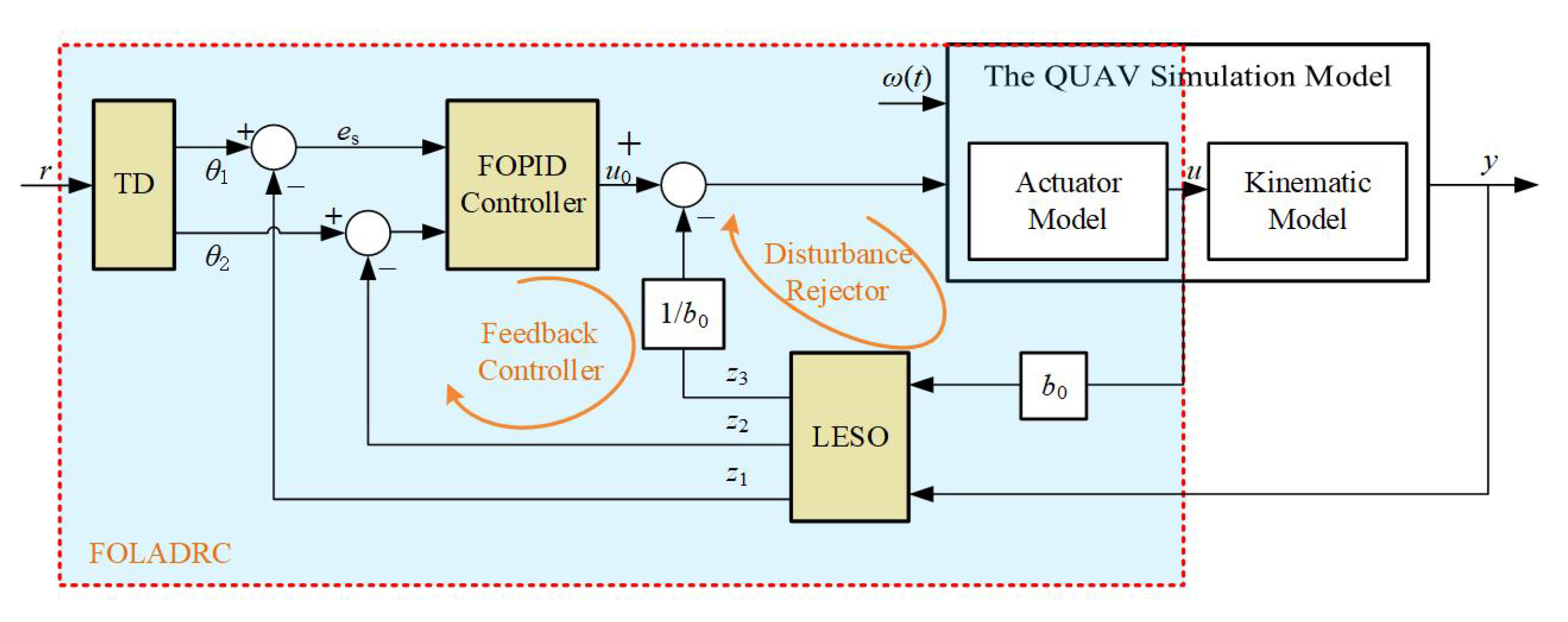
3. FOLADRC Design for Quadrotor UAV
Accurate attitude control is crucial for the quadrotor UAV to achieve high flight performance. Therefore, FOLADRC is applied to enhance the robustness and rapidity of the quadrotor UAV. We assume that the structure of the quadrotor UAV is symmetrical, therefore the pitch and roll channels have the same control structure. Besides, the yaw controller is designed with the same process as horizontal control. Consequently, only the control scheme of the pitch channel is discussed in this paper. According to Equation (11), the dynamic model of the pitch channel can be simplified as follows:
where
represents the pitch angle of the system,
represents the external disturbance generated by the environment such as gusty wind, and
represents the nominal model.
U is the pitching moment acting on the quadrotor UAV.
b =
represents the controller gain, where
is the estimated value of
b and
is the system uncertainty parameter. Since the dynamic of pitch channel is a second-order system, a second-order FOLADRC controller can be applied to control it. FOLADRC consists of the tracking-differentiator (TD), the FOPID controller, and the linear extended state observer (LESO). The structural diagram of the FOLADRC-based system is shown in
Figure 3.
- (1)
Tracking-differentiator
The input signal, called the desired pitch angle, is supposed to be
r, and the equation of TD can be given as:
where
e represents the pitch error.
h and
r0 are the filtering factor and speed factor, respectively. The fhan
is the optimal control synthetic function and it can be expressed as:
- (2)
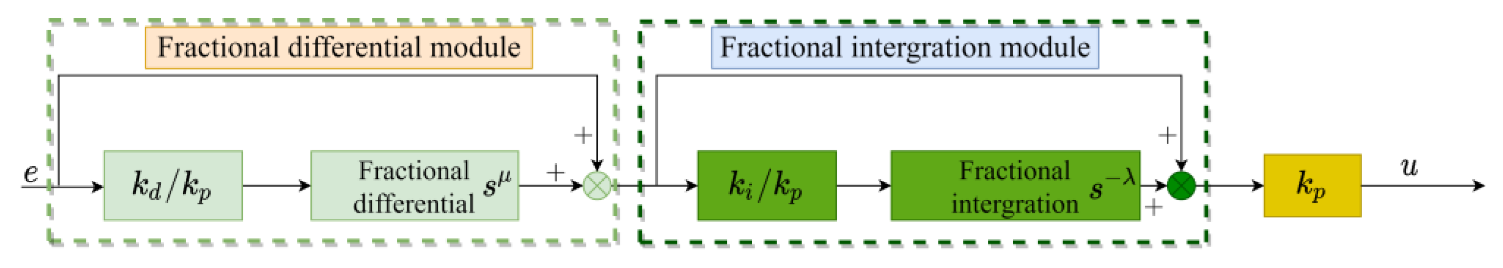
Error Feedback
Compared with the traditional PID, FOPID introduces two fractional calculus operators,
λ and
μ, to improve the control performance. Generally, the FOPID controller extends the traditional PID into the fractional-order field, which inherits the advantages of the PID and has stronger robustness. The transfer function of FOPID is described as:
where 0 <
λ < 2 and 0 <
μ < 2. To enhance the dynamic property of the system in the mid-frequency range and simplify parameter tuning, Equation (15) can be rewritten as:
The structural diagram of FOPID is shown in
Figure 4.
- (3)
Linear Extended state observer
After estimating the total disturbance by LESO, the disturbance in a system can be compensated. Thus, the system has a strong anti-disturbance ability. The equation based on Equation (12) is established as follows:
where
z1,
z2, and
z3 are the estimated values of the pitch angle, the rate of change of the pitch angle, and total disturbance, respectively.
,
, and
are the observer gains that need to be tuned, and
u is the control input.
Since this paper focuses on the control performance of FOLADRC, taking
as the reference, the controller bandwidth
=
is calculated according to the bandwidth method [
15]. Then, the poles of LESO are assigned to (−
,0) according to the observer bandwidth
, and
.
In summary, the design of FOLADRC has been completed.
4. Parameter Tuning of FOLADRC Based on L-SSA
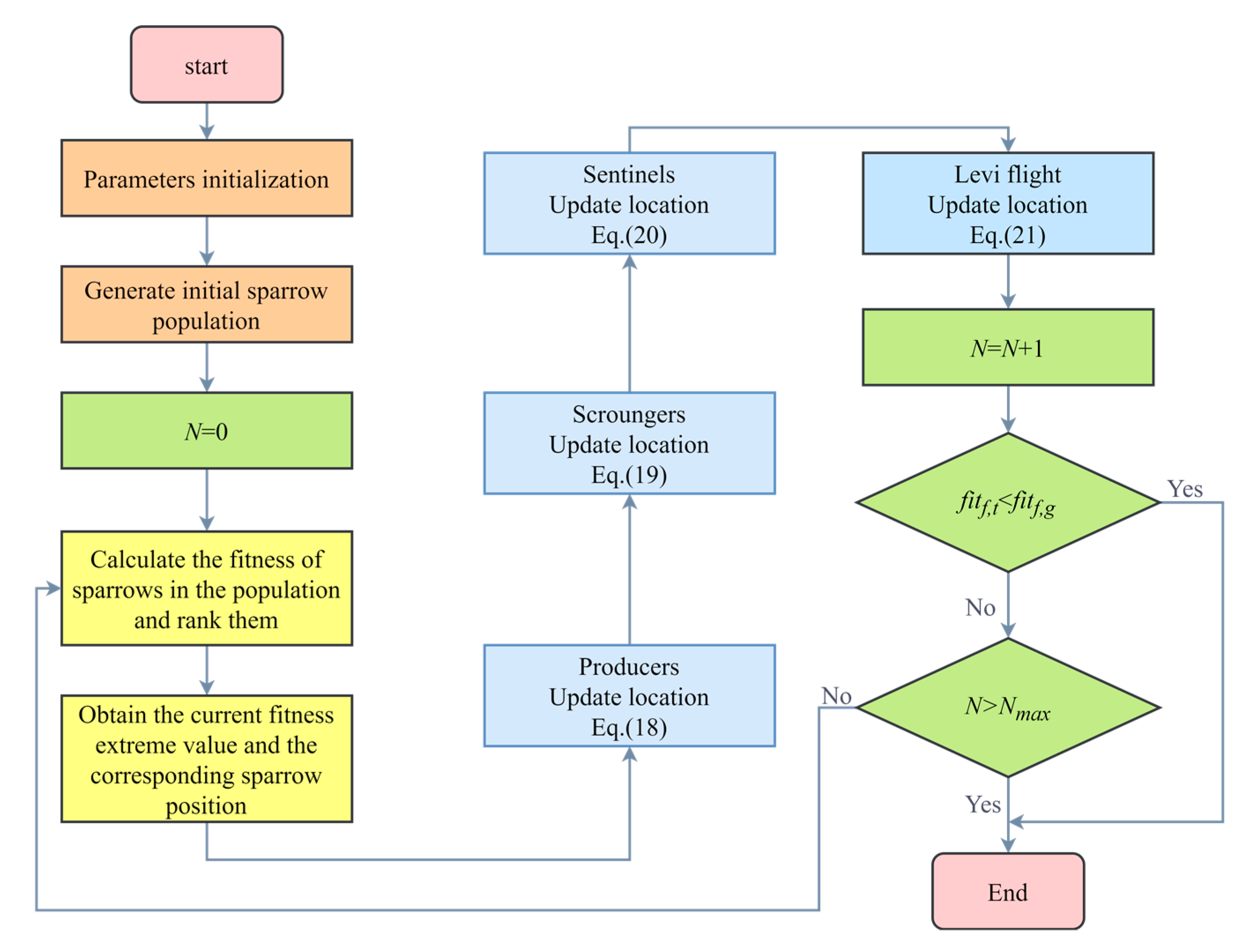
4.1. L-SSA
The sparrow population consists of producers, scroungers, and sentinels.
Figure 5 shows the relationship between the three types of sparrows. The producers are responsible for finding food for the entire sparrow population and providing foraging directions for all scroungers. The scroungers follow the producers and compete with them for food resources or forage around them. The sentinels will issue an alarm and move to a safe location after discovering the natural enemies.
where
N represents the current iteration times,
represents the position information of the
ith sparrow in the
jth dimension, and
L is an all-one matrix of dimension 1 × d. Random number
R2 ∈ [0, 1],
γ ∈ (0, 1),
Q ~ N(0, 1), and
St is a safe value.
The scroungers search for the producers with the highest energy, and their updated location can be represented as:
where
is the optimal position occupied by the producers after the position update,
is the worst position in the current global, and
A is a real matrix with values ± 1. When
, the
ith hungry scrounger migrates to other regions for foraging to obtain more energy because of having no food.
After discovering the natural enemies, the sentinels at the edge of the population will quickly move to a safe area, and the sentinels in the middle of the population will approach other sparrows by walking randomly. The updated location of sentinels can be described as:
where random number
K∈[0, 1],
~ N(0, 1), and
is a small quantity to remove the effect of a possible 0 denominator.
and
represent the minimum and maximum values of the fitness function, respectively.
As mentioned in the introduction, SSA lacks an excellent mutation mechanism and is prone to fall into local optimum. Consequently, the “Levy flight” strategy of nature is introduced. It uses the random walk strategy to generate large jumps and sharp direction changes in the process of position updates, to avoid the sparrow individuals being bound by local extreme values, and at the same time to open up the foraging search space, which effectively improves the high-dimensional optimization effect of the sparrow algorithm.
The Levi mutation is represented as follows:
where
is the Levi mutation factor and
.
The flowchart of L-SSA is shown in
Figure 6, and the details of the optimization process are as follows:
Step 1. Initialize parameters of L-SSA, such as the sparrow population n, the proportion of producers Pt, iterations Nmax, etc. Set the position of each sparrow randomly and the number of initial iterations as 0.
Step 2. Calculate the fitness of each sparrow to obtain the current fitness limit value and the position of the corresponding sparrow.
Step 3. The n × Pt sparrows with the least fitness are selected as the producers, and the remaining sparrows are scroungers, and the positions are updated according to Equations (18) and (19). Then, sentinels are randomly generated, and their positions are updated according to Equation (20). Calculate the fitness of each sparrow after the location update.
Step 4. Calculate the inertia weight factor , and adopt the tournament rules to extract sparrows to participate in the tournament. The least fit sparrows are selected for the Levi flight, and the positions are updated according to Equation (21).
Step 5. If the current global fitness minimum value is not greater than the minimum optimal fitness , the optimization is stopped, otherwise step 5 continues.
Step 6. If the iteration time N is equal to the , the optimization is stopped. If not, reorder and update the population class, and finally loop into step 3.
4.2. Fitness Function and Parameters Tuning
To obtain better control performance, the fitness function based on the time domain index and frequency domain index is set as:
where
X(
X= [
]) represents the optimized parameter variable,
t represents the system simulation time, and
e(
t) represents the pitch angle command tracking the error of the quadrotor UAV.
and
represent the phase angle margin and cut-off frequency of the open-loop control system, respectively.
is the desired system phase angle margin,
represents the desired cut-off frequency, and
,
,
,
are the weight of each item in the fitness function.
According to the control system, let
= 27 rad/s,
= 60°, and the upper and lower limits of the control parameters [
] are: [1, 0, 0, 0.1, 0.1], [20, 10, 10, 1.9, 1.9]. The design fitness function parameters are shown in
Table 1.
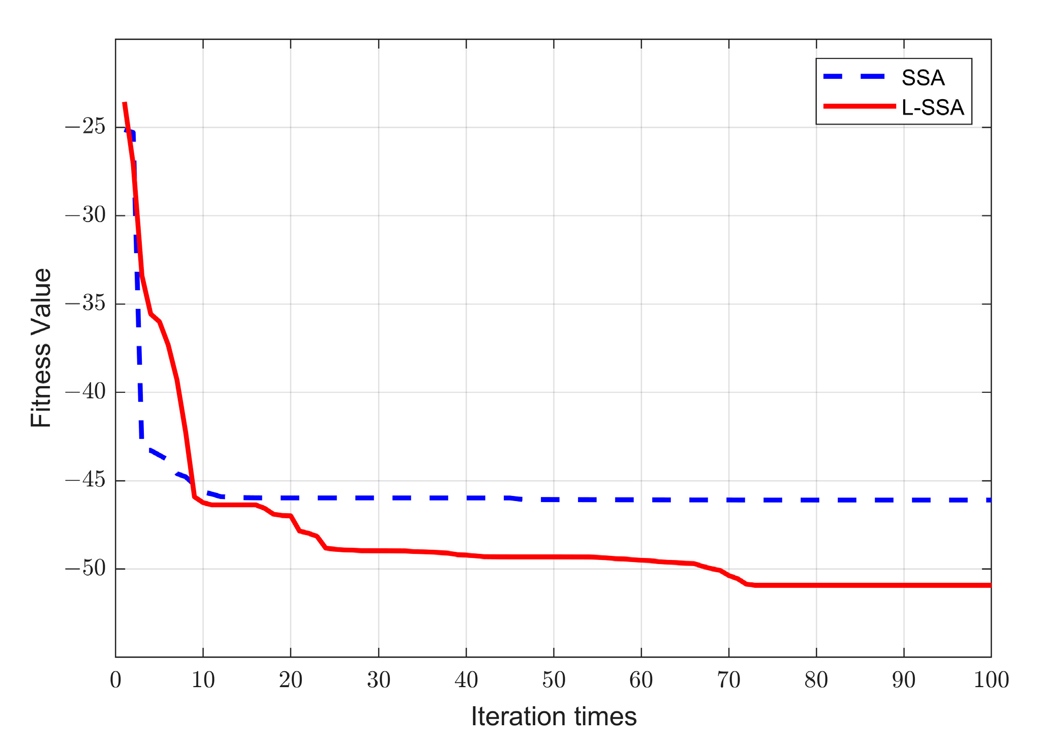
The fitness changes in the optimization process of the SSA and L-SSA are shown in
Figure 7. As shown in
Figure 7, the convergence speed of SSA is very fast. After ten iterations, the fitness value does not change, while for the LSSA, after 80 iterations, the value of fitness function tends to be stable. However, compared with the final optimized fitness function value, L-SSA is significantly better than SSA, so it can be concluded that L-SSA can handle the problem of SSA easily falling into the local optimum.
Eventually, the parameters of FOPID are obtained as
kp = 11.9078,
ki = 1.6273,
kd = 1.3649,
λ = 0.92925, and
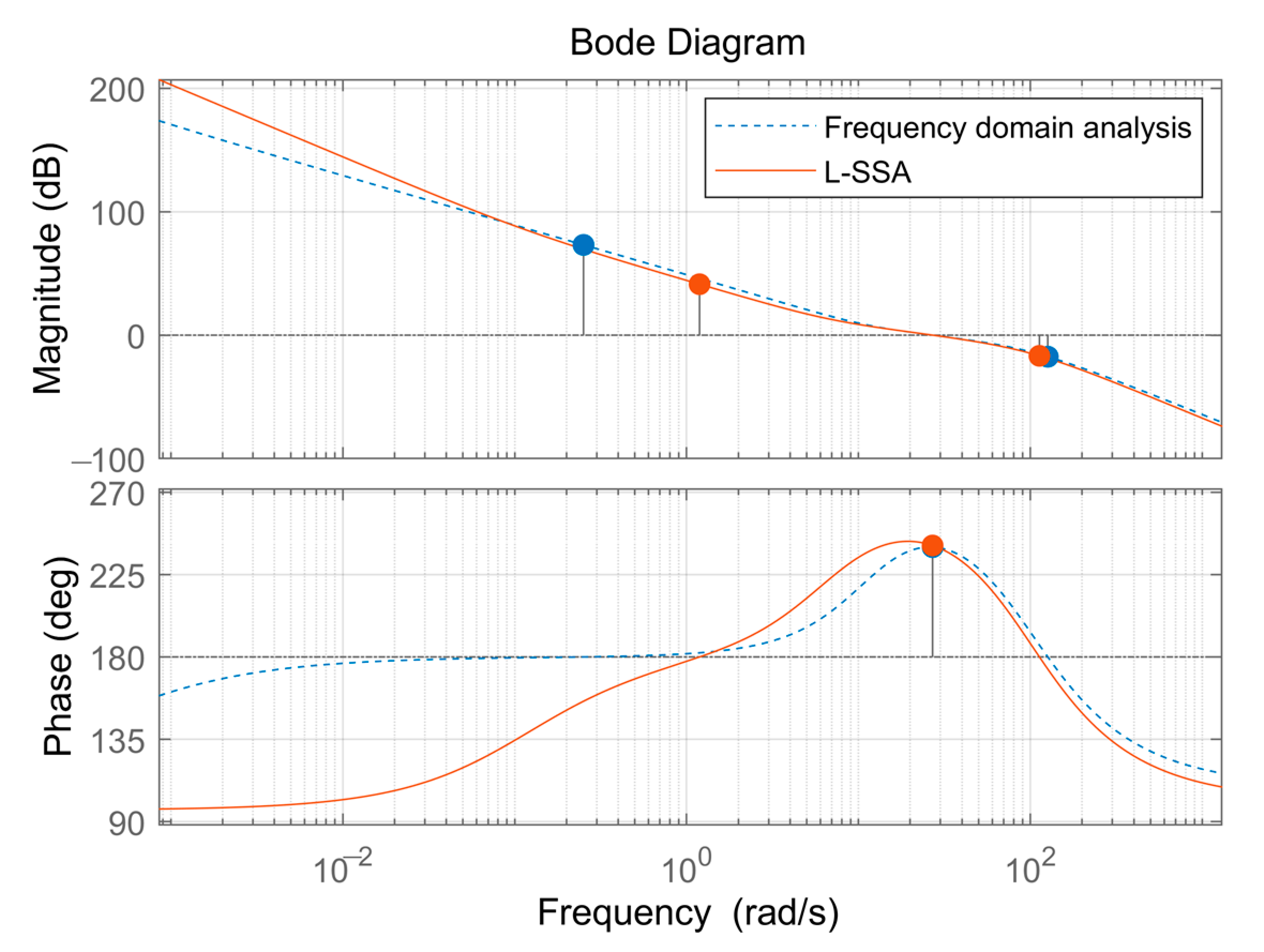
μ = 1.1262. Compared with the parameter tuning method based on frequency domain performance indicators [
26], its Bode diagram is shown in
Figure 8, the time domain response is shown in
Figure 9, the system performance parameters are shown in
Table 2, and the time domain indicators are shown in
Table 3.
Figure 8 shows that both parameter tuning methods can ensure the phase angle margin and cutoff frequency are near the desired value. As shown in
Table 2, the phase angle change rate
at the cutoff frequency of the FOPID open-loop system tuned by the frequency domain optimization algorithm is almost 0, but compared with the FOPID parameters optimized based on the L-SSA, the average phase angle
near the cutoff frequency is 0. The fitness function index shows that the fitness function of the L-SSA is smaller, and its performance index is better.
It can be seen from
Figure 9 and
Table 3 that the fractional-order PID controller tuned based on the L-SSA has a smaller adjustment time and overshoot. Consequently, the FOPID open-loop system optimized based on the sparrow algorithm has better time-domain and frequency-domain performance.
5. Simulation and Experimental Analysis
5.1. Simulation Verification
Assume the initial states of the quadrotor are x = z = 0, h = 0 m, V = 0 m/s, θ = φ = ψ = 0°.
To observe the performance of three different controllers, the quadrotor is controlled under three conditions, including undisturbed, external disturbance, and parameter perturbation. The parameters of each controller tuned by L-SSA are shown in
Table 4.
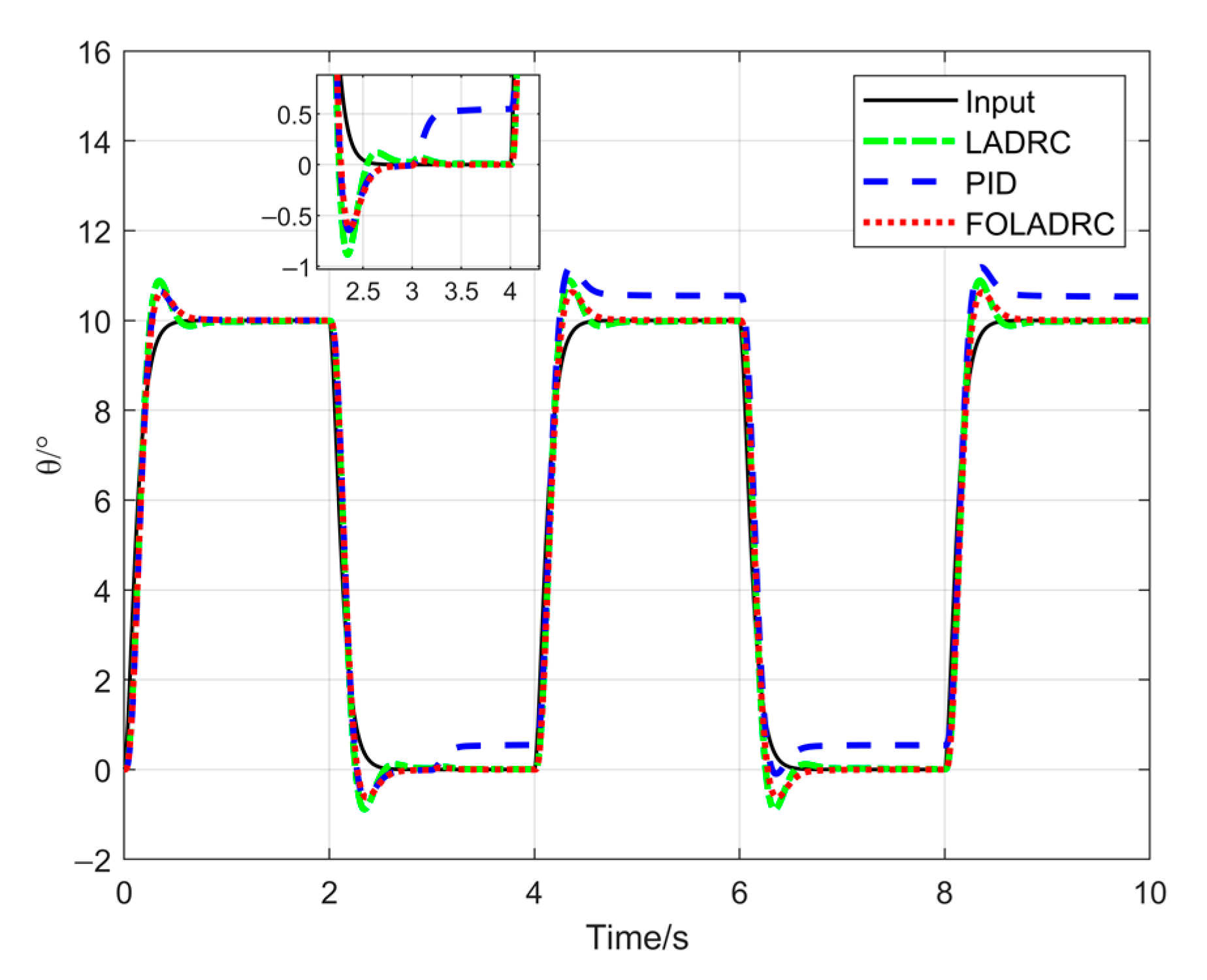
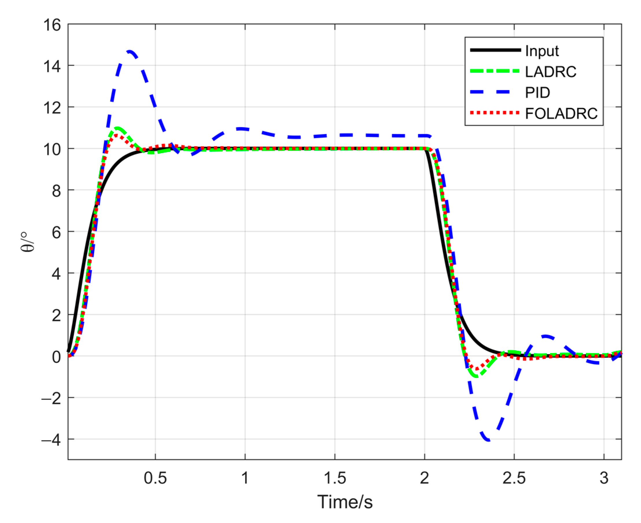
The desired pitch angle signal is given as a square wave signal with an amplitude of 10° and a period of 4 s, and the simulation curves of each controller are as in
Figure 10.
Figure 10 shows that the control system based on FOLADRC has a smaller overshoot and smaller adjustment time compared with the control system based on PID and LADRC. However, the performance indicators of the three controllers are not very different.
Due to the absence of internal uncertainties and external disturbances, the disturbance values estimated by LADRC and FOLADRC are small, and the LESO does not have large disturbance compensation. Consequently, the performance of the control system based on PID, LADRC, and FOLADRC is similar.
In this condition, the pitching moment disturbance is applied at 3 s and can be equivalent to a sine disturbance, that is
The simulation results according to Equation (23) are as follows:
It can be seen from
Figure 11 that the quadrotor system under FOLADRC or LADRC has smaller steady-state errors than PID since LESO can observe the external disturbance torque and cancel it. In addition, from
Figure 11, it can be known that under external disturbance, the overshoot of FOLADRC has been reduced by 11% compared with LADRC.
Assuming that the actual system deviates from the nominal system, the parameter perturbation Δ
b0 = 5 is selected for simulation control and the simulation curves are as in
Figure 12 and
Figure 13:
In this case, the control system based on FOLADRC and LADRC can achieve good control performance, but the overshoot of FOLADRC controller has been reduced by 38%. Furthermore, the FOLADRC and LADRC controllers have more robustness compared with the PID controller.
Generally speaking, under the three conditions, both FOLADRC and LADRC controllers have better control performance, and the FOLADRC controller can track the desired pitch angle faster and more accurately, showing no steady-state errors. Consequently, the quadrotor UAV-based FOLADRC has good control performance and strong robustness.
5.2. Verification of Aircraft Experimental Platform
The flight experiment uses Pixhawk flight control and PX4 firmware. The control period of the flight control is 0.004 s.
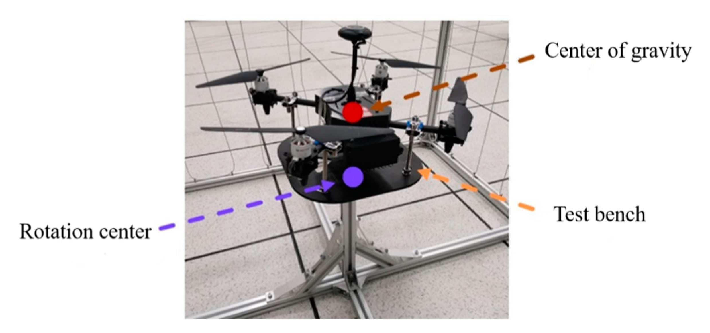
To ensure the safety of the flight experiment and the conditions are the same, the quadrotor UAV is placed on the flight test bench. The test bench used for the flight experiment is shown in
Figure 14:
It can be seen from
Figure 14 that the quadrotor UAV is fixed on the test bench and can be rotated around the center of rotation. Since the quadrotor UAV rotates around the center of rotation of the test bench during the test, disturbance related to the altitude angle (
) will be generated during the altitude control process due to the influence of the center of gravity.
d is the distance from the center of gravity of the quadrotor UAV to the center of rotation of the test bench.
The parameters of controllers are set according to
Table 4.
The desired pitch angle signal is given as a step signal with an amplitude of 10°, and the experiment results of each controller are as follows:
It can be seen from
Figure 15 that in the initial stage of the quadrotor UAV maneuvering, the system control performance based on LADRC, PID, and LADRC methods overlap, but when the pitch angle is further increased, the tracking performance of the three control methods appears to be relatively different. In the initial stage of command tracking, the disturbance
received by the quadrotor UAV is small due to the small sinα. As the pitch angle continues to increase, the disturbance becomes larger. Because the PID cannot observe the disturbance, it only relies on a small integral term to offset the influence of the disturbance, so there is a large error. The LESO in LADRC can observe the disturbance
in time and cancel it, so the overshoot is small, and the error is quickly eliminated. Compared with LADRC, FOLADRC can also cancel the disturbance error in time, which can perform instruction tracking faster and has stronger robustness.
To further verify the control performance and anti-disturbance characteristics of FOLADRC, an artificial external disturbance was applied to the quadrotor UAV to observe the control performance of the FOLADRC control law. The disturbance experiment is shown in
Figure 16.
As shown in
Figure 16, a water bottle with a weight of 300 g was placed on one axis of the test bench with an elastic rope when it was in a horizontally stable state. Due to the elasticity of the elastic rope, the water bottle will vibrate up and down and rotate around the axis of the elastic rope, which further causes the water in the bottle to flow, thereby introducing a large nonlinear disturbance into the quadrotor UAV to test the control performance of FOLADRC. The experiment results are shown in
Figure 17:
It can be seen from
Figure 17 that the control system based on PID produces a large amount of overshoot due to the disturbance of the external load, while the control system based on LADRC and FOLADRC has an increase in overshoot compared to the no-load disturbance. Compared with LADRC, the overshoot of FOLADRC has been reduced by 37% and the adjustment time has been reduced by 60%.
In addition, the anti-disturbance performance of the FOLADRC controller is tested by applying a sudden load disturbance. The experimental results are shown in
Figure 18.
It can be seen from
Figure 18a that at the moment of applying the disturbance, the control systems based on PID, LADRC, and FOLADRC all deviate from the equilibrium point to a certain extent, among which the PID controller deviates the most from the equilibrium point, while the FOLADRC method has the smallest error.
Figure 18b,c show the changes in the disturbance observations of the control system based on LADRC and FOLADRC after loading the disturbance. When the disturbance load is applied to the quadrotor UAV, the disturbance observations of both controllers increase rapidly, thereby canceling the overshoot caused by the disturbance. The disturbance value has a certain vibration at the beginning. Compared with the LADRC method, the disturbance observation value of the FOLADRC method has smaller vibration and can be stabilized to a certain value in a short time, so that the entire system stabilizes quickly.
Consequently, based on the above simulation experiments and flight tests, it can be seen that the quadrotor UAV control method based on FOLADRC has better control performance and strong robustness in the case of the nominal disturbance-free condition, external load disturbance, and parameter uncertainty.
6. Conclusions
Since the ADRC system is sensitive to the system controller gain, the fractional calculus operator was introduced in this paper to improve the robustness and control performance of the system. This paper studied the design method of the FOLADRC controller for a quadrotor UAV and solved the problem that the attitude control accuracy and stability of the quadrotor UAV are greatly reduced under large parameter uncertainty and strong external disturbance. To verify the feasibility of the designed control system implemented in the quadrotor UAV system, this paper applies the designed FOLADRC controller to the UAV platform in nominal experiments and anti-disturbance experiments. The experimental results show that the designed control system has the advantages of smaller adjusting time, less overshoot, and stronger robustness, which demonstrates that FOLADRC has greater advantages in practical engineering applications.
In addition, a parameter tuning method of the FOLADRC controller based on the L-SSA was proposed, which not only solves the problem that basic SSA easily falls into local optimization, but also settles the issue that the FOLADRC parameter tuning method based on the frequency domain index cannot take into account the rapidity, accuracy, and reliability of the time domain at the same time.


