Article

Robust Neural Network Consensus for Multiagent UASs Based on Weights’ Estimation Error

by
Alejandro Morfin-Santana
1,
Filiberto Muñoz
1,2,*,
Sergio Salazar
1 and
José Manuel Valdovinos
1
1
Laboratory LAFMIA-UMI, Center for Research and Advanced Studies of the National Polytechnic Institute (CINVESTAV), Mexico City 07360, Mexico
2
Mexican National Council of Science and Technology (CONACYT), Mexico City 03940, Mexico
*
Author to whom correspondence should be addressed.
Drones 2022, 6(10), 300; https://doi.org/10.3390/drones6100300
Submission received: 2 September 2022 / Revised: 30 September 2022 / Accepted: 7 October 2022 / Published: 13 October 2022
(This article belongs to the Special Issue Multi-UAVs Control)

Abstract

:
We propose a neural network consensus strategy to solve the leader–follower problem for multiple-rotorcraft unmanned aircraft systems (UASs), where the goal of this work was to improve the learning based on a set of auxiliary variables and first-order filters to obtain the estimation error of the neural weights and to introduce this error information in the update laws. The stability proof was conducted based on Lyapunov’s theory, where we concluded that the formation errors and neural weights’ estimation error were uniformly ultimately bounded. A set of simulation results were conducted in the Gazebo environment to show the efficacy of the novel update laws for the altitude and translational dynamics of a group of UASs. The results showed the benefits and insights into the coordinated control for multiagent systems that considered the weights’ error information compared with the consensus strategy based on classical σ -modification. A comparative study with the performance index ITAE and ITSE showed that the tracking error was reduced by around 45%.

1. Introduction

In the last couple of decades, exhaustive research and development began in the field of unmanned aerial vehicles in search and rescue, surveillance, monitoring and mapping the environment, and delivery and transportation tasks [1,2]. Moreover, it is widely recognized both in nature and in robotic systems that the development of a task or mission in a cooperative way offers different advantages, among which are a reduction in time, a robustness or tolerance to failures since a member that presents problems can easily be replaced by some other agent [3,4]. In this sense, consensus methods for multiagent systems (MAS) have a extensive use in the field of intelligent autonomous vehicles, such as unmanned aircraft systems vehicles (UASs), ground vehicles, and sea applications. In [5], for UAV multiagent systems with external disturbances, a finite-time distributed-formation-tracking strategy was used. The authors in [6] applied in sliding mode a consensus algorithm to track the leader in multi-UAS systems and maintain the desired formation at the same time.
With the aim of solving the problem of formation control, more attention was given to the consensus control of multiagent systems, because of their extensive application in several areas [7,8]. Mainly, consensus control is divided into two approaches [9,10], the leaderless and the leader–follower consensus. Firstly, the consensus protocols were designed for linear systems, ranging from first-order integrator systems to higher-order integrator systems [11,12]. Because of the applicability of the consensus algorithm, further developments were conducted. The consensus strategy has been developed for nonlinear systems [10,13], with time-delay [14,15], with the input and actuator saturated [11,16], with sliding-mode techniques [17,18], as well as regarding algorithms dealing with external uncertainties within systems with unknown dynamics [19]. With the development of computational resources, strategies focused on machine learning have been proposed, where, based on the observations of both the states in multiagent systems and the environment, they have to improve both the performance and communication within the consensus algorithm [20,21].
An extended survey of consensus algorithms can be founded in [22,23].
In recent years, in order to solve the problem of lumped disturbances, i.e., unmodelled dynamics and external disturbances, several neural network nonlinear consensus approaches have been developed. Moreover, these protocols are efficient when the model parameters change while the system is working, as is the case with UAVs performing logistics tasks [24]. In this sense, further research on consensus protocols based on neural networks has been conducted in [25,26]. For nonlinear multiagent systems with uncertainties, a leader–follower consensus with state and output feedback was presented in [27], where the uncertain dynamics were approximated through neural networks. An adaptive neural consensus strategy for nonaffine nonlinear multiagent systems with uncertainties, unknown control directions, and subject to switching topologies was developed in [28], where a radial basis neural network was used to approximate the unknown dynamics. A neuronal dynamic surface control based on a predictor was developed for nonlinear systems subject to uncertain dynamics in [29]; in contrast to existing methodologies where the neural weights are updated with information from the tracking errors, a predictor was used and the prediction errors were employed in the adaptation law for the neural weights. In [30], a robust consensus strategy was developed for high-order nonlinear multiagent systems subject to unknown dynamics, affected by unknown actuator failures and unknown control gains. In this approach, a backstepping was combined with a neural network to ensure that the tracking error was restricted to a small region. In [31], an output-feedback formation tracking control strategy with modeling uncertainties subject to communication constraints was developed, where a radial basis neural network was used to identify the unknown dynamic.
In the aforementioned works, a major limitation is that the only signal available that reflects the difference between estimated parameters and the real parameters is the tracking or prediction error signal. To increase the robustness of the adaptive laws, the neural network consensus protocols were improved by introducing variants in the adaptive laws for the neural weights, such as the modification σ [32] and the modification e [33]. However, these algorithms induced a longer convergence time and affected the response of the tracking error. As stated in [34,35] for adaptive control systems, a fast and accurate neural network weight estimation convergence is valuable for the stability and robustness properties in closed-loop systems.
Since the optimal weights are unknown, the difference between the estimated weights and the optimal weights is not available for measurement. Based on the previous observations, an adaptive estimation strategy for unknown parameters was first introduced in [36], where, unlike conventional adaptation mechanisms, the adaptation of parameters included information on the estimation error of the parameter to increase the convergence of the tracking errors.
Motivated by the use of the parameter estimation error in the development of adaptive laws, further research was conducted by the scientific community. The development of robust adaptive controllers for the online estimation of the mass parameter for robotic systems was reported in [37]. In [38,39], an adaptive parameter estimation strategy was developed to estimate parameters in vehicle systems, mainly the road gradient and the mass of the vehicle. Moreover, an adaptive control strategy was developed for vehicles’ active suspensions subject to unknown nonlinearities in [40]; in that approach, the authors proposed an adaptive law based on the parameter estimation error. This novel parameter estimation strategy was used in aerial systems as well. In [41], the inertia and mass parameters of a quadrotor aerial vehicle were estimated by introducing the parameter estimation error. Furthermore, following the same methodology, the inertia and mass parameters of a six-DOF spacecraft were estimated in [42]. Recently, in addition to being used to estimate unknown parameters, this parameter estimation methodology was employed to estimate the optimal weights for systems based on a neural network [43]. In [44], an adaptive control strategy for robot manipulators was developed by combining a neural controller and a robust controller. The proposed scheme guaranteed that the estimated weights converged in finite time to the optimal weights. Furthermore, for robotic systems, in [45], a sliding mode controller enhanced with a neural network was developed. In that approach, an adaptive law for the neural weights was proposed, which was based on the estimation error. For a dual-arm robot system with dynamic uncertainties, an adaptive command-filtered control strategy was designed in [46]. Moreover, a radial basis neural network was used to approximate the uncertainties of the system, where the information of the estimated error was used in the adaptive law for the neural weights.

Main Contributions

We propose a robust, adaptive-consensus cooperative strategy for a group of quadrotor aerial vehicles with lumped disturbances (i.e., partially unknown nonlinearities and external disturbances). In order to compensate for the lumped disturbances, a radial basis neural network is introduced in the consensus protocol. To calculate the information of the weights’ estimation error, a set of first-order intermediate variables are computed. Finally, the adaptive laws for the neural network weights incorporate the information of the estimation error. The main contributions of this research work are listed below:
  • The development of a leader–follower consensus algorithm enhanced with a radial basis neural network for multiagent quadrotor unmanned aircraft systems subject to lumped disturbances is presented.
  • The algorithm used to update the weights of the neural network is based on a first-order filter and auxiliary matrices to obtain the weight error information and use it in the adaptation law. To the best our knowledge, the consensus algorithms with neural network compensation reported until now have not taken into account the weight error information in the adaptation law.
  • A stability proof based on Lyapunov’s theory is developed for the consensus algorithm and neural network compensation developed, where the uniformly ultimate boundedness of the (i) formation errors and (ii) neural weights’ estimation errors, is guaranteed.
  • Simulation experiments for multiagent UAV systems are performed over the ROS platform [47] and ROS-based Gazebo environment.
The document is organized as follows: Some preliminaries and the dynamic model for the UAV are reviewed in Section 2. The consensus control strategy is introduced in Section 3. Section 4 provides the simulation results with examples in Gazebo, and Section 5 concludes this paper.

2. Preliminaries and Dynamic Model of the UAV

In this section, we introduce the graph theory necessary for the development of the consensus control strategy. After that, the general mathematical model for the quadrotor vehicle is presented. However, the quadrotor aerial vehicle simulated in Gazebo has an internal controller for the rotational dynamics. Simulations are conducted to identify the dynamics of the internal controller and finally a mathematical model that includes the internal controller dynamics is presented.

2.1. Graph Theory

Formally, the agents and a leader in a multiagent system are simply nodes, denoted by N, and the connectivity/structure among the agents is define by a communication graph G = { , ϝ } where = { n 1 , , n N } is a node set and ϝ = { ( n i , n j )   × is an edge set composed by the elements ( n i , n j ) that represent the communication link with i as the origin node and j as the final node. The so-called adjacency matrix is defined as A = ( a i j ) R N × N , where the element a i j of A is selected as a i j = 1 if node n i is connected to node n j and a i j = 0 if is disconnected. A very important and practical feature is the degree of each node, which is simply the number of nodes that it is connected to; the in-degree matrix is D = d i a g ( d i ) R N × N , it provides a single value of each node, with d i = j N i a i j . It is also used for the computation of the most important graph operator, the graph’s Laplacian L = ( l i j ) R N × N , defined as L = D A . If a i j = a j i , for i , j = 1 , , N , then the communication graph G is defined as an undirected graph. If there is a path connecting every pair of nodes, then an undirected graph is connected. Furthermore, the leader’s adjacency matrix is defined as A 0 = diag ( a i 0 ) R N × N , where a i 0 > 0 implies that agent ith has access to the state of the leader agent and a i 0 = 0 in another case. If the undirected graph is connected and at least one of diagonal entries of the leader’s adjacency matrix is not zero, then the matrix H defined as H = L + A 0 R N × N is symmetric and positive definite [48].

2.2. Dynamic Model of the Quadrotor UAV

A brief description of the mathematical model is shown below [49,50]. In Figure 1, we observe a three-dimensional UAV, where Γ B = X B , Y B , Z B represents the body-fixed frame located in the center of gravity of the vehicle. The inertial frame is represented by Γ I = X I , Y I , Z I , and the position vector for the aerial vehicle in the inertial frame is denoted as ξ = ( x , y , z ) Γ I . In this work, the rotation matrix used is given by
R ( η ) = c ψ c θ c ψ s θ s ϕ s ψ c ϕ c ψ s θ c ϕ + s ψ s ϕ s ψ c θ s ψ s θ s ϕ + c ψ c ϕ s ψ s θ c ϕ c ψ s ϕ s θ c θ s ϕ c θ c ϕ
where R ( η ) : Γ I Γ B and R ( η ) S O ( 3 ) . ψ , θ , and ϕ are referred to as the Euler angles representing yaw, pitch, and roll, respectively. Moreover s · and c · stand for sin · and cos · , respectively.
Let ξ ˙ and η ˙ be defined as the linear and angular velocities of the three-dimensional vehicle expressed in the inertial frame. Moreover, the linear and angular velocities represented in the body-fixed frame are denoted by ξ ˙ b and η ˙ b , respectively. Then, η = [ ϕ θ ψ ] T Γ I represents the vector of Euler angles, and η ˙ b = [ p q r ] T , as the body angular velocities are related to η ˙ = W η ˙ b , where the matrix W is defined as
W = 1 s ϕ tan θ c ϕ tan θ 0 c ϕ s ϕ 0 s ϕ c θ c ϕ c θ
Using the Newton–Euler equations, we can represent the equations of motion of the UAV in the body frame as follows
m ξ ¨ = R ( η ) v z F m g v z
J ( η ) η ¨ = τ C ( η , η ˙ ) η ˙
Here, J ( η ) = W I W acts as the inertia matrix, where I = d i a g ( I x , I y , I z ) and C ( η , η ˙ ) η ˙ = J ˙ ( η ˙ b J ) 2 η η ˙ b represents the Coriolis term, v z = 0 0 1 is a unitary vector along the z-axis in the inertial reference frame, F is the thrust force applied to the aerial vehicle, and τ R 3 denotes the roll, pitch, and yaw moments. The multirotor UAV model given previously is a highly coupled nonlinear system. Under some assumptions, it is possible to redefine the above model. Now, to simplify the moments τ , the auxiliary vector τ ˜ is defined as follows
τ ˜ = u 2 / I x u 3 / I y u 4 / I z = I 1 W 1 I W ˙ η ˙ W η ˙ × I W η ˙ + τ
Using (3) and (4), the UAV dynamical model can be represented by
x ¨ = u 1 m ( cos ψ sin θ cos ϕ + sin ψ sin ϕ )
y ¨ = u 1 m ( sin ψ sin θ cos ϕ cos ψ sin ϕ )
z ¨ = u 1 m ( cos θ cos ϕ ) g
θ ¨ = u 2 I x
ϕ ¨ = u 3 I y
ψ ¨ = u 4 I z
where m R represents the mass of the aerial vehicle and g R is the force due to the gravity, and u 1 = i = 1 4 T i is the thrust, which is generated by the rotors of the vehicle. For simplicity, the generalized torques are obtained as
u 2 u 3 u 4 = l T 1 l T 2 + l T 3 + l T 4 l T 1 + l T 2 + l T 3 l T 4 C M T 1 + C M T 2 C M T 3 + C M T 4
where C M is a constant defined from the rotor characteristics and l is the distance from the center of mass of the vehicle to the center of the rotor.

2.3. Modeling UAV Multirotor in Gazebo

The quadrotor available in Gazebo considers the presence of a low-level attitude controller provided by the PX4 autopilot. The internal controller stabilizes the angular dynamics for the roll, pitch, and yaw angles as well as the altitude in the z-axis direction. In a effort to consider the dynamics of the internal controller, we assumed that those dynamics were represented by the following differential equations
z ¨ = a 1 z ˙ a 2 z + a 3 u z
θ ¨ = b 1 θ ˙ b 2 θ + b 3 u θ
ϕ ¨ = c 1 ϕ ˙ c 2 ϕ + c 3 u ϕ
ψ ¨ = d 1 ψ ˙ d 2 ψ + d 3 u ψ
where u z , u θ , u ϕ , and u ψ denotes the control inputs to the quadrotor aerial vehicle. In order to identify the parameters a i , b i , c i , and d i of Equation (7), a set of simulations was conducted in Gazebo by using step functions as control inputs and recording the input–output data. With the collected data, we used the System Identification Toolbox of MATLAB, which estimated the parameters of the dynamic model (7) by using the least squares method. Table 1 summarizes the parameters obtained.
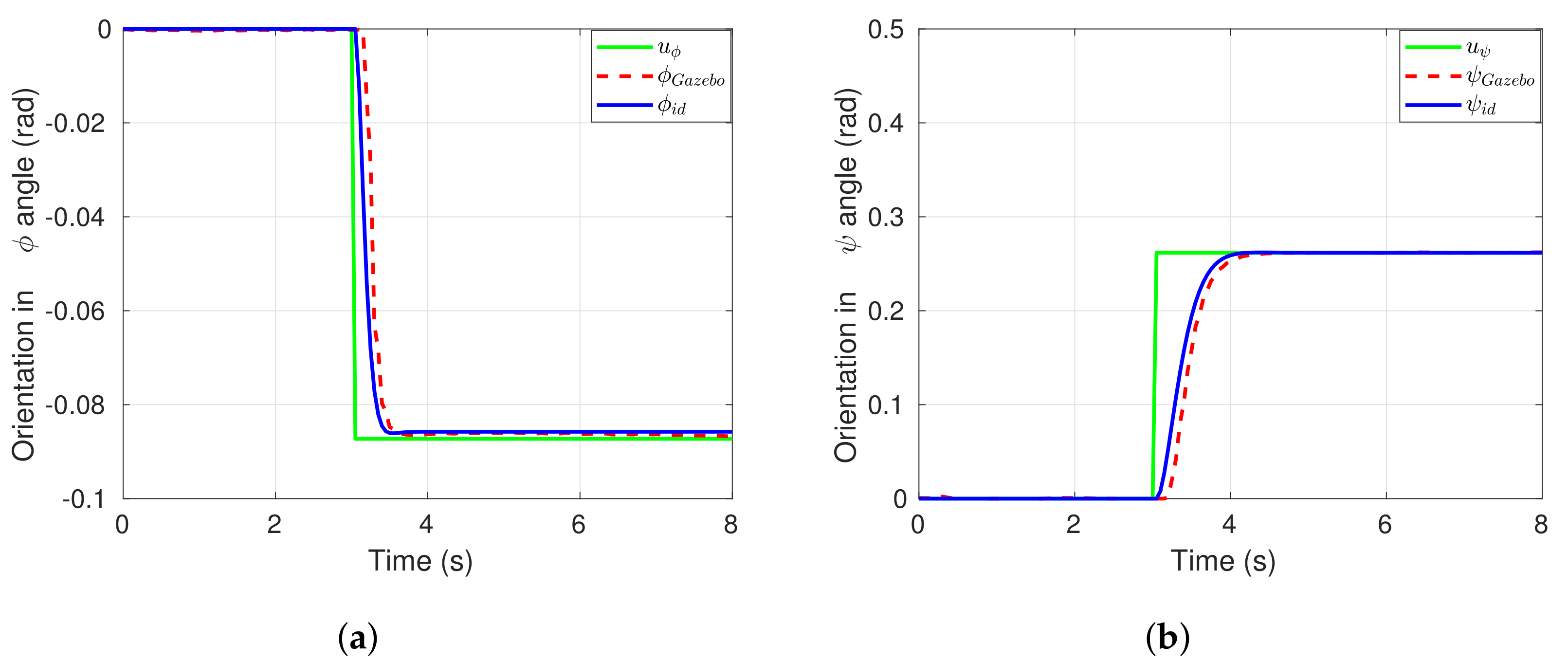
The model was further validated by comparing the results obtained through simulations in Matlab with the data obtained from Gazebo. We can observe in Figure 2a the output from the experimental test for the z dynamics using as control input step function and the result for the transfer function. This procedure was similar within the attitude dynamics, where the control inputs of the Iris drone were related with the Euler angles as shown in Figure 2b and Figure 3a,b.
From Equations (5c) and (7a), we could obtain for the control signal u 1 the following
u 1 = m a 1 z ˙ a 2 z + a 3 u z + g cos θ cos ϕ
Substituting (8) in (5a) and (5b) and combining with the dynamics identified, we obtained a complete model that took into account the dynamics of the internal controller, and was given as
x ¨ = f ( z , u z ) ( cos ψ tan θ + sin ψ cos θ tan ϕ )
y ¨ = f ( z , u z ) ( sin ψ tan θ cos ψ cos θ tan ϕ )
z ¨ = a 1 z ˙ a 2 z + a 3 u z
θ ¨ = b 1 θ ˙ b 2 θ + b 3 u θ
ϕ ¨ = c 1 ϕ ˙ c 2 ϕ + c 3 u ϕ
ψ ¨ = d 1 ψ ˙ d 2 ψ + d 3 u ψ
where f ( z , u z ) = ( a 1 z ˙ a 2 z + a 3 u z + g ) .

3. Control Strategy Development

In this section, we introduce the development of the consensus cooperative strategy for the multiagent system. In view of the underactuated property of the quadrotor vehicle, we rewrite the mathematical model of the quadrotor vehicle presented in Equation (9). After that, the consensus strategy for the translational dynamics of the team of quadrotor aerial vehicles is developed.

3.1. Mathematical Model for the Consensus Development

Before the development of the consensus control strategy for the multiagent quadrotor system, we rewrite Equation (9) to obtain a general equation to be used in the development of the consensus control strategy. From (9a) and (9b), we can define the virtual control inputs u x and u y as follows
u x u y = ( a 1 z ˙ a 2 z + a 3 u z + g ) tan θ tan ϕ cos θ tan ϕ cos θ tan θ cos ψ sin ψ
where u x and u y can be translated to the desired roll and pitch angles. Therefore, in this matrix representation, we can obtain the desired references angles ϕ d and θ d that enable the system to follow the desired positions x d and y d ; the desired angles are given as
ϕ d = arctan ( u x cos ψ + u y sin ψ ) f ( z , u z )
θ d = arctan ( u x sin ψ + u y cos ψ ) cos ϕ d f ( z , u z )
We assume that the Euler angles (roll, pitch, and yaw) are bounded in the following ranges: ( π / 2 < θ < π / 2 ) , ( π / 2 < ϕ < π / 2 ) and ( π < ψ < π ) , respectively.
With the definitions of u x and u y , the dynamics of translation for each quadrotor vehicle are given by
x ¨ = u x
y ¨ = u y
z ¨ = a 1 z ˙ a 2 z + a 3 u z
The control inputs u x , u y , and u z are computed for each vehicle through the consensus control strategy developed in Section 3.2. Once u x and u y are calculated, the desired angles ϕ d and θ d are obtained by using (11). Moreover, we assume that the yaw reference angle is set to zero ψ d = 0 . Finally, the desired angles ϕ d , θ d and ψ d are the inputs for the internal controller of each aerial vehicle in the ROS environment.

3.2. Consensus Control Strategy

Now, the consensus cooperative strategy enhanced by a radial basis neural network is developed. First, it is developed for the altitude subsystem given in Equation (12c). For the horizontal plane, given by Equations (12a) and (12b), it is worth mentioning that the development of the cooperative strategy follows the same structure as that for the altitude subsystem.

3.2.1. Consensus Control Strategy for Altitude Dynamics

The control strategy designed assumes that the aforementioned low-level altitude controller has as its input a velocity command given by u z . Therefore, we need to define the altitude controller such that it converges to the altitude desired and it has the capability to counteract the unknown disturbances. For this reason, we need to begin with the vertical dynamics given in (12c), which can be rewritten for each agent as
z ˙ i = A z z i + B z ( u z i + d z i ) , i = 1 , , N ,
where z i = [ z 1 i z 2 i ] , A z = 0 1 a 2 a 1 , B z = 0 a 3 , and d z i denotes external uncertainties. Moreover, we introduce the leader’s dynamics as follows
z ˙ 0 = A z z 0 + B z r ( z 0 , t )
where r ( z 0 , t ) is a bounded input for the leader agent. The following assumption is stated in order to deal with the external disturbances d z i
Assumption 1.
The matched uncertainty d i z for the altitude dynamics defined in (13) is approximated by a radial basis neural network as
d z i = W z i * Ψ z i ( z i ) + ϵ z i z i D
where W z i * R s is an unknown constant optimal weight vector. Ψ z i ( · ) : R n R s represents a vector function as Ψ z i ( z i ) = [ Ψ 1 i ( z i ) , Ψ 2 i ( z i ) , , Ψ s i ( z i ) ] T where Ψ i ( x ) is a radial basis activation function, which can be represented as: if Ψ i ( x ) = e x p ( | | x c | | 2 2 b 2 ) , i = 1 , 2 , , N , where the center and width of the Gaussian functions are represented by c R r and b, respectively. Moreover, the activation function satisfies | | Ψ z i | | Ψ M i with Ψ M i > 0 , the approximation error ϵ z i fulfills | ϵ z i | ϵ z i + where ϵ z i + > 0 , and D R n is a sufficiently large domain [29].
Now, we define the tracking error for each follower agent as δ z i = z i z 0 , whose time derivative is along (13), (14), and using the approximation (15), we obtain
δ ˙ z i = A z z i + B z ( u z i + W z i * Ψ i ( z i ) + ϵ z i ) A z z 0 B z r = A z δ z i + B z ( u z i + W z i * Ψ i ( z i ) + ϵ z i r )
With the aim to develop the adaptation procedure for the neural weights W ^ z i , inspired by the approach presented in for single systems, a set of first-order filters is introduced. It is worth mentioning that with this approach, we can use information about the weight error W ˜ z i , in contrast to classical adaptation mechanisms. To conduct this strategy, the tracking error dynamics (16) are parameterized as
δ ˙ z i = A z δ z i + B z u z i + B z Ψ i ( z i ) T W z i * + B z ( ϵ z i r ) = φ z i ( δ z i , u z i ) + Φ z i W z i * + ε z i
where
φ z i ( δ z i , u z i ) = A z δ z i + B z u z i , Φ z i = B z Ψ i ( z i ) T , ε z i = B z ( ϵ z i r ) ,
with φ z i ( δ z i , u z i ) R 2 and Φ z i R 2 × s is defined as the “regressor” matrix.
In this sense, the filtered variables δ z i f , φ z i f and Φ z i f are defined as
k δ ˙ z i f + δ z i f = δ z i , δ z i f ( 0 ) = 0 k Φ ˙ z i f + Φ z i f = Φ z i , Φ z i f ( 0 ) = 0 k φ ˙ z i f + φ z i f = φ z i , φ z i f ( 0 ) = 0 k ε ˙ z i f + ε z i f = ε z i , ε z i f ( 0 ) = 0
where k > 0 is a filter parameter. In order to obtain from (17) and (19) that
δ ˙ z i f = δ z i δ z i f k φ z i f = Φ z i f W z i * + ε z i f .
let us define two auxiliary matrices P z i R s × s and Q z i R s as
P ˙ z i = l P z i + Φ z i f T Φ z i f , P z i ( 0 ) = 0 Q ˙ z i = l Q z i + Φ z f T [ δ z i δ z i f k φ z i f ] , Q z i ( 0 ) = 0
where the positive scalar l is a parameter to be designed. The solution of (21) is derived as
P z i = 0 t e l ( t r ) Φ z i f T ( r ) Φ z i f ( r ) d r Q z i = 0 t e l ( t r ) Φ z i f T ( r ) δ z i ( r ) δ z i f ( r ) k φ z i f ( r ) d r
Lemma 1.
The auxiliary matrix P z i defined in (22) is positive definite, λ min P z i > σ Φ > 0 , if the regressor Φ z i presented in (18) fulfills the PE condition [45]. A function Φ z i satisfies the PE condition if there exist positive constants T and γ satisfying the condition t t + T Φ z i r T Φ z i r d r γ I , t 0 .
Notice that from (20) and (22), we can rewrite Q z i as
Q z i = P z i W z i * ϱ z i
where ϱ z i = 0 t e l ( t r ) Φ z i f ( r ) ε z i f ( r ) d r R s . As ε z i and the regressor Φ z i are bounded, we obtain that the filtered variables Φ z i f and ε z i f are also bounded. Therefore, ϱ z i is bounded by ε z i f + > 0 .
Based on the solutions of P z i and Q z i , we define an auxiliary vector H z i as:
H z i = P z i W ^ z i Q z i
Then, based on (22) and the parameter estimation error W ˜ z i = W z i * W ^ z i , we can verify that
H z i = P z i W ^ z i Q z i = P z i W ^ z i P z i W z i * + ϱ z i = P z i W ˜ z i + ϱ z i .
To guarantee the stability of the tracking error δ z i , we design the following distributed control law with augmented adaptive control term
u z i = c z K z e z i W ^ z i T Ψ z i ( z i ) ,
where W ^ z i is an estimate of the unknown weights W z i * , the scalar c z is a coupling gain, and e z i is a neighborhood error represented as
e z i = j N a i j ( z i z j ) + a i 0 ( z i z 0 ) ,
Define K z R 1 × 2 as K z = B z T M z , where M z is the solution of the Riccati inequality defined as
A z T M z + M z A z + N z M z B z B z T M z 0 ,
Notice that M z and N z R 2 × 2 are positive definite matrices. If the consensus control law (26) is substituted into (16), we arrive at
δ ˙ z i = A z δ z i + B z ( c z K z e z i W ^ z i T Ψ z i ( z i ) + W z i * Ψ z i ( z i ) + ϵ z i r ) = A z δ z i + B z ( c z K z e z i + W ˜ z i Ψ z i ( z i ) + ϵ z i r ) .
It should be noted from (25) that the information about the weights’ estimation error W ˜ z i is contained in H z i . Then, the adaptation law, for the weights of the ith follower agent in the altitude dynamics is proposed as
W ^ ˙ z i = Γ z i ( Ψ z i ( z i ) e z i T M z B z k z i H z i ) .
where Γ z i and k z i are positive constants. Then, we state the theorem for the consensus cooperative control for the altitude dynamics of the quadrotor multiagent system as follows.
Theorem 1.
Consider the altitude dynamics for the ith follower agent given in Equation (13). If the regressor Φ z i defined in (18) fulfills the PE condition, the cooperative control strategy u z i is proposed as in Equation (26), the gain K z is obtained from solving the Riccati Equation (28), the coupling gain c z fulfills condition (58), and the neural weights are updated by the adaptive law given by Equation (30), where the auxiliary matrix H z i is defined in Equation (24). Then, the altitude tracking error δ z i and the estimation error of the neural weights W ˜ z i for the ith agent converge to a bounded region defined by (66).
Proof. 
The proof of this Theorem is presented in Section 6.    □

3.2.2. Consensus Control Strategy for Position Control in the Horizontal Plane

To obtain the consensus control strategy for the XY plane, it is necessary to carry out the development of a consensus strategy for each axis. In this sense, we present the development for the X axis and notice that for the Y axis the procedure is similar. Consider the dynamics for the X axis presented in Equation (12a), which is rewritten as
x ˙ i = A x x i + B x ( u x i + d x i )
where x i = x 1 i x 2 i , A x = 0 1 0 0 , B x = 0 1 , and d x i denotes the external uncertainties. Moreover, the leader dynamics are given as
x ˙ 0 = A x x 0 + B x r x x 0 , t .
Let us define the tracking errors for the ith agent in the X axis as δ x i = x i x 0 . The distributed control strategy is proposed as
u x i = c x K x e x i W ^ x i T Ψ x i ( x i ) ,
where c x is a scalar coupling gain, W ^ x i is an estimate of the unknown weights W x i * , and the neighborhood synchronization error in the X axis is defined as
e x i = j N a i j ( x i x j ) + a i 0 ( x i x 0 )
Similar to Equation (30), the updated law for the weights of the neural network is given by
W ^ ˙ x i = Γ x i ( Ψ x i ( x i ) e x i T M x B x k x H x i ) ,
where we can observe that the knowledge of the estimation error of the neural weights is incorporated in the term H x i , which is defined as
H x i = P x i W ^ x i Q x i
The auxiliary filtered matrices P x i and Q x i are defined as in (21). The filtered variables δ x i f , φ x i f , and Φ x i f are defined as in Equations (18) and (19). For the purpose of guaranteeing the convergence of the tracking errors δ x i and the weights’ estimation error W ˜ x i , Theorem 1 can be applied for the consensus control strategy in the X and Y axes.

4. Simulation Results

The simulation results for the robust cooperative control strategy developed are presented in this section. First, we introduce the simulation environment, where the required steps to carry out the simulations trials in ROS and Gazebo are summarized in Algorithm 1. After that, we present two simulations scenarios. The first one is for the altitude control of a team of four quadrotor aerial vehicles, with a comparative study with a classical distributed control and adaptive distributed control. In the second one, the simulation results for the translational cooperative control in the plane XY are presented.

4.1. Simulation Environment

In this section, we present the implementation of the algorithm within the Gazebo robotics simulator, it allows the testing of the behavior of multirotor vehicles without the need to use physical systems, due to the complexity of the tests and the fact it requires a greater number of components due to the number of vehicles that we defined as follower agents in this simulator. The environment can be constituted from the tools and packages developed by PX4 [51], which supports the connection with an embedded computer through a standardized protocol called Mavlink. We can observe that in the following Algorithm 1, we have to set the windy environment with the gazebo plugin that introduces external disturbances, followed by the number of agents to be used, then the topics and services are created for each vehicle. The Algorithm 1 summarizes the program developed.
Algorithm 1 Algorithm to set the multiagent system tests.
Drones 06 00300 i001

4.2. Simulation Scenarios

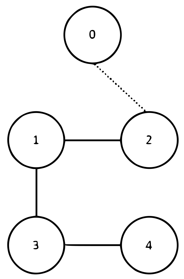
In these simulation results, we considered the configuration of the multiagent system with N = 4 multirotor vehicles. Each aircraft had a mass m = 1.5 kg and the communication graphs utilized in the simulations are represented in Figure 4.
For the communication graph of Figure 4, the adjacency and in-degree matrices were defined as
A = 0 1 1 0 1 0 0 0 1 0 0 0 0 0 1 0 , D = 2 0 0 0 0 1 0 0 0 0 1 0 0 0 0 1
Moreover, the Laplacian and leader’s adjacency matrices were defined as
A 0 = 0 0 0 0 0 1 0 0 0 0 0 0 0 0 0 0 , L = 2 1 1 0 1 1 0 0 1 0 1 0 0 0 1 1
In order to show the performance of our proposed approach, we present a comparative analysis with two other consensus control strategies presented in the literature.
  • Classical nominal distributed control. In this approach, a static control strategy is used, given by
    u z i = c z K z e z i ,
    which uses only the coupling gain c z , the feedback gain K z , and the neighborhood error e z i [52].
  • Adaptive neural network consensus control. In this strategy, a radial basis neural network is employed to compensate the lumped disturbances. The consensus cooperative strategy and the update law for the neural weights are presented below, where the weights are updated using the conventional method [53]
    u z i = c z K z e z i W ^ z i T Ψ z i ( z i ) W ^ ˙ z i = Γ z i ( Ψ z i ( z i ) e z i T M z B z k z i W ^ z i )
    In comparison with our approach, notice that for the neural weights, the adaptation law (40) includes the estimation of the weights given by the term W ^ z i .

4.2.1. Altitude Control

The mathematical model for the altitude dynamic of the ith agent can be written as follows
z ˙ i = 0 1 0.1093 0.1862 z i + 0 1.2737 ( u z i + d z i )
For the leader agent, we selected a bounded input given as r ( t ) = 6 3 cos t 3.5 .
Table 2 presents the parameters used for this simulation scenario, including the control gains, the gains of the robust estimator, and the gains for updating the neural weights.
A radial-based neural network was used, where the output of this neural network is given in Equation (15). The neural network proposed had 25 neurons, where the centers of the neural weights were chosen as
c e n z = 2 2 2 2 2 3.5 3.5 3.5 3.5 3.5 5 5 5 5 5 7.5 7.5 7.5 7.5 7.5 9 9 9 9 9 0.6 0.3 0 0.3 0.6 0.6 0.3 0 0.3 0.6 0.6 0.3 0 0.3 0.6 0.6 0.3 0 0.3 0.6 0.6 0.3 0 0.3 0.6
with b = 0.7 as the width of the hidden neuron. Furthermore, the initial weights of the network were selected randomly.
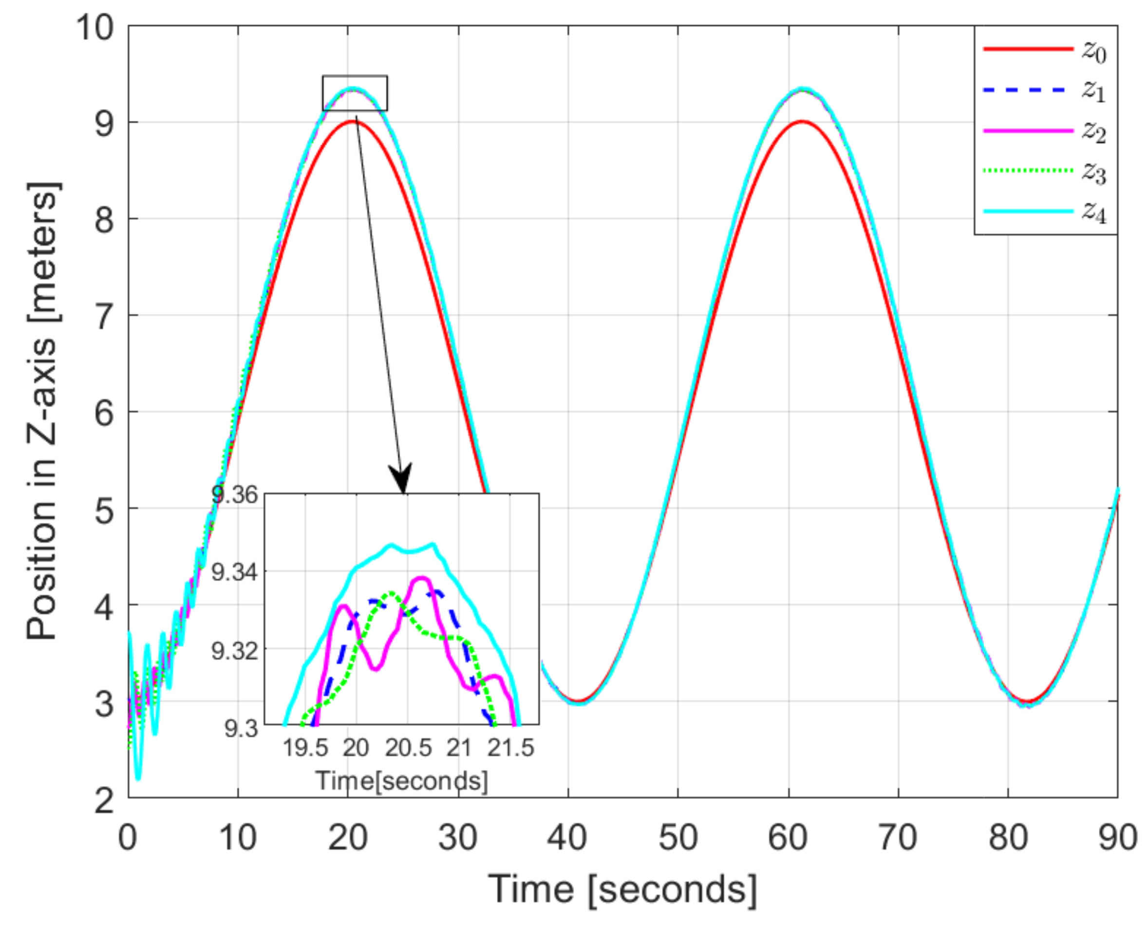
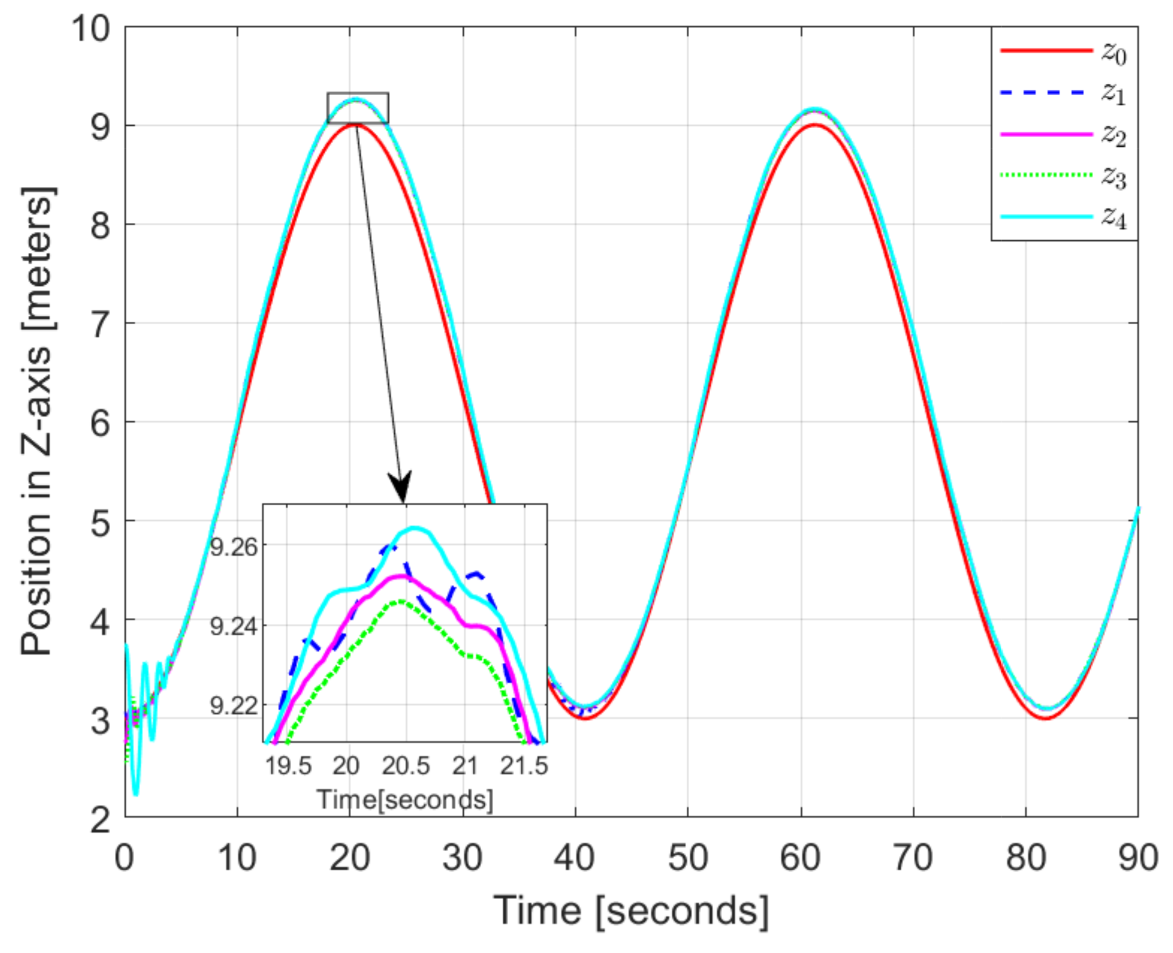
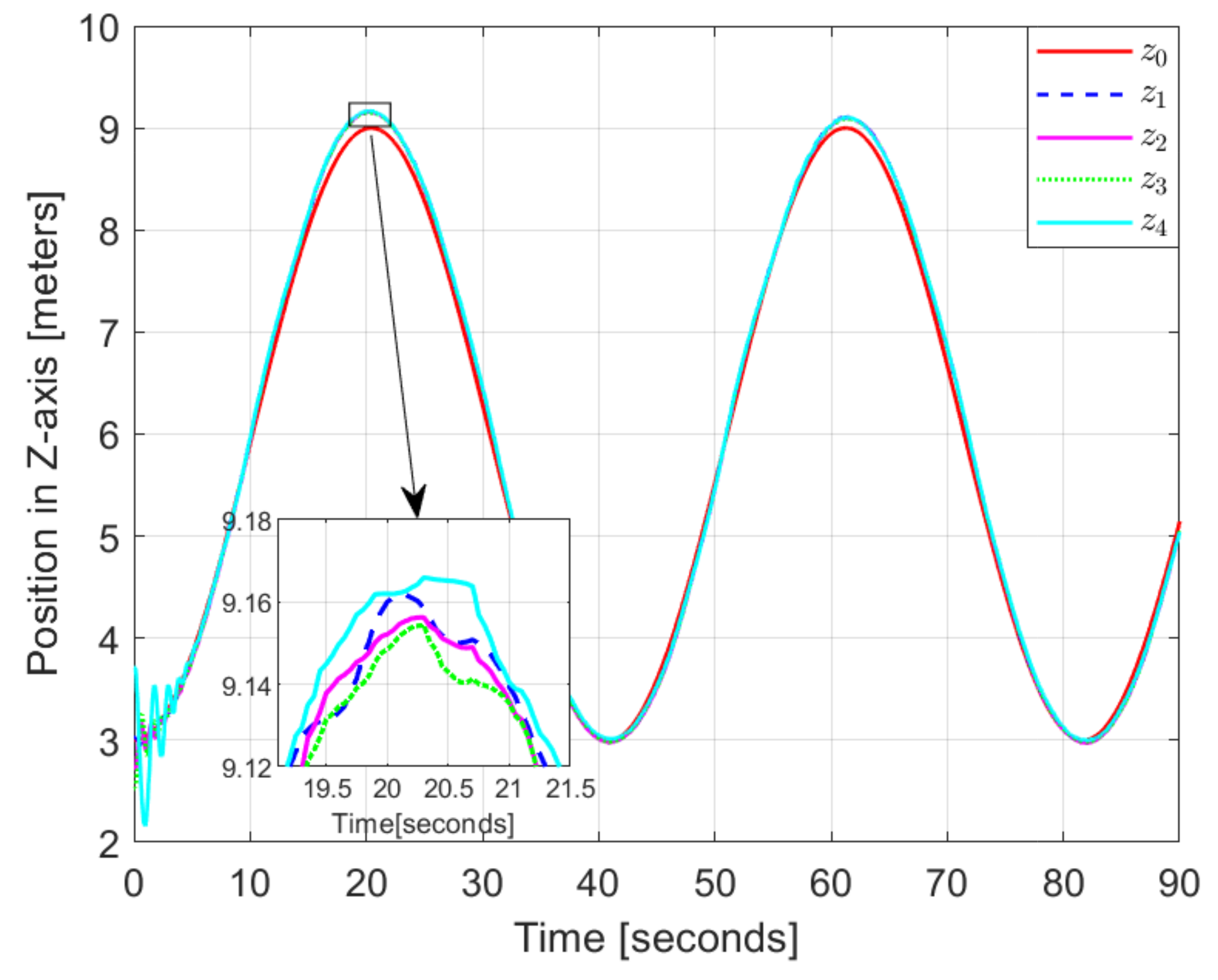
As we can see in Figure 5, a classic controller was used that was stationary so the tracking error performed by the agents was constant at 20 and 60 s. Furthermore, in the zoomed rectangle, we can see that the vehicles oscillated more in comparison to the reference virtual agent. In the second scenario in Figure 6, we can see the effects of the adaptive term as the tracking error began to decrease. However, the update law to estimate the parameters generated oscillations, specifically in the lower part, at 40 and 80 s. The robust estimator was introduced in the third scenario and we can observe in Figure 7 how the tracking error converged and the oscillations were reduced. In this work, to verify the effectiveness of the strategy proposed, we used two performance indices based on the tracking error between each one of the follower agents and the leader agent.
The indices used were the integral-time absolute error (ITAE) and integral-time square error (ITSE). The performance values are shown in Table 3 where as can be seen, the values in each index decrease and improve in our approach compared with the other methods.

4.2.2. Translational Cooperative Control

The dynamic model in the horizontal plane formed by the X and Y axes can be written as follows:
x ˙ i = 0 1 0 0 x i + 0 1 ( u x i + d x i ) y ˙ i = 0 1 0 0 y i + 0 1 ( u y i + d y i )
It is worth mentioning that from the consensus control signals u x i and u y i , the desired reference angles ϕ d i and θ d i were obtained and used as control inputs for the quadrotor vehicles.
In order to follow a circular trajectory, the reference for the leader agent in the X and Y axes were given as
r x t = ( 3 cos t π 20 + 3 ) 3 r y t = 3 sin π 20 t
The number of neurons was similar to the neural network for the height dynamics and the width b = 0.7 , and the centers of the neural weights were
c e n x = 6 6 6 6 6 3 3 3 3 3 0 0 0 0 0 3 3 3 3 3 6 6 6 6 6 0.6 0.3 0 0.3 0.6 0.6 0.3 0 0.3 0.6 0.6 0.3 0 0.3 0.6 0.6 0.3 0 0.3 0.6 0.6 0.3 0 0.3 0.6
The parameters and the initial conditions changed the effect, when analyzing the performance of the proposed algorithm as we can observe in Table 4. Note that the centroids and parameters described in Table 4 for the X-axis dynamics were the same for the Y-axis dynamics of the system.
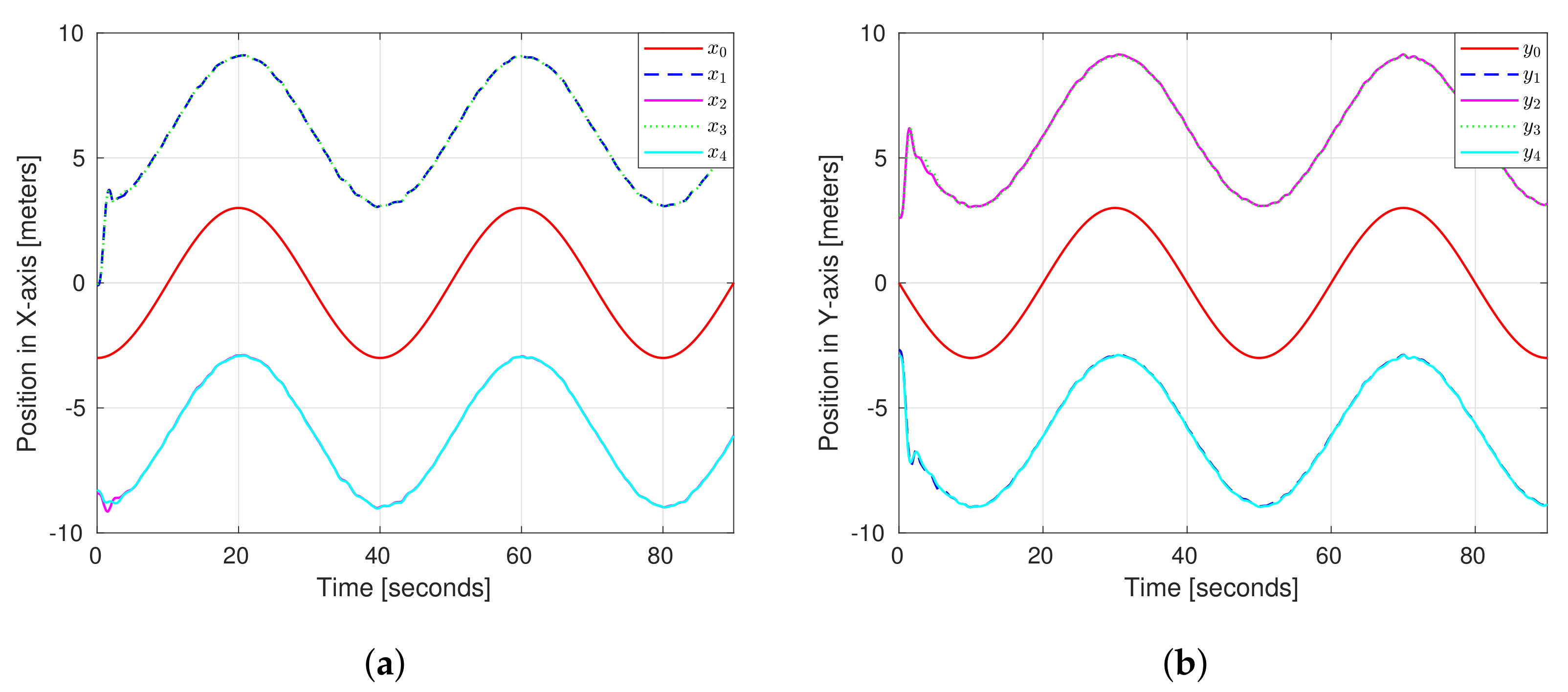
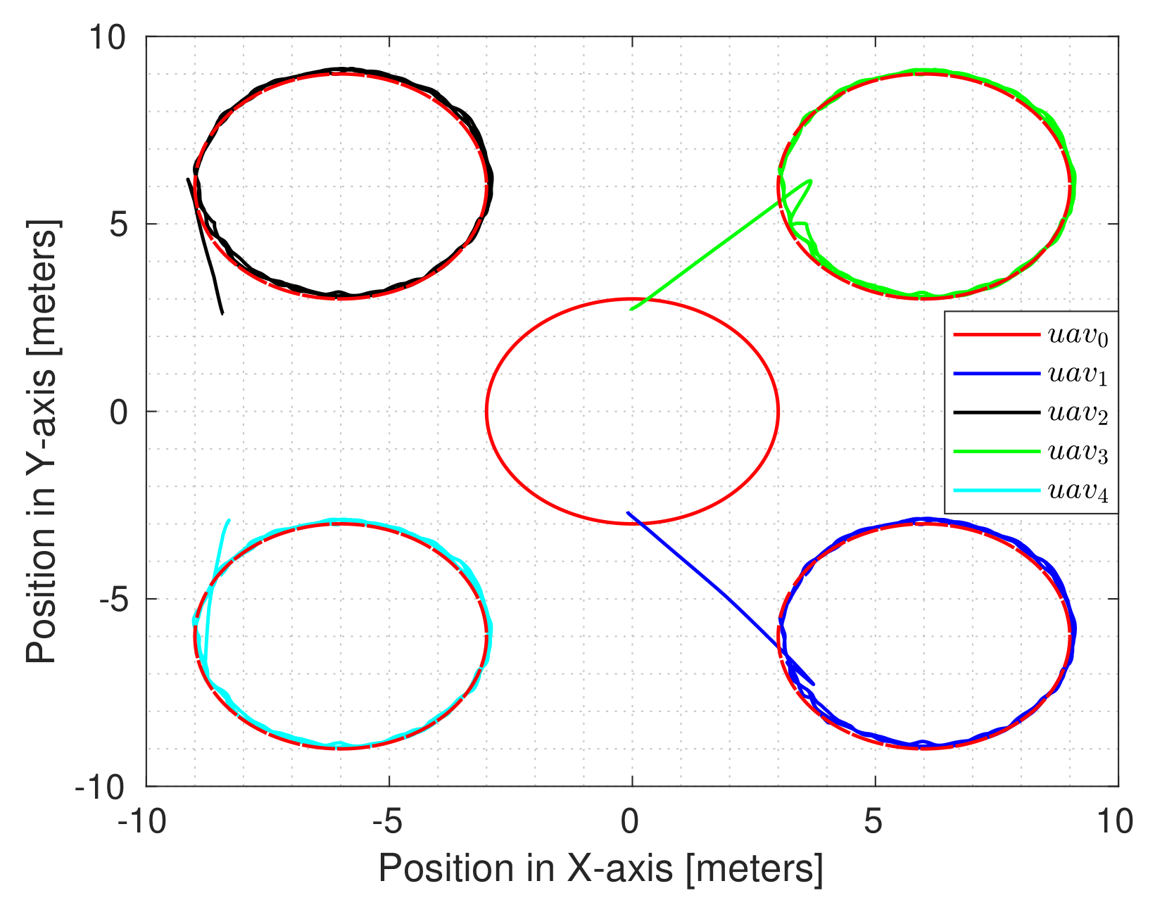
In Figure 8, we present the results of the simulations with the conditions mentioned above. The reference of the virtual leader agent was a circular path in the X–Y plane centered on [ 0 , 0 ] and the circular references for each vehicle maintained an offset of their centers of ± 6 m. Last, in Figure 8a,b, we can observe the performance of the position of the UAVs in the X and Y axes, respectively, where we can see two vehicles following the circular trajectory in their respective offsets despite having a wind disturbance d x , y = 1 m s with a positive direction on the horizontal plane X-Y. In Figure 9, we show the point of view of the trajectory of the follower agents, where we can observe how the tracking error converges; a video showing the simulations in the Gazebo environment was shared at https://youtu.be/i6Qp5MMB2Ws (accessed on 22 June 2022).

5. Conclusions

A consensus protocol with a robust neural network estimator for the unknown elements and flock motion was proposed for multi-UAV systems to reduce the tracking error subject to unknown external perturbations and unmodeled dynamics. The closed-loop stability for the whole system was verified through Lyapunov’s theory, arriving at a result of a uniformly ultimately bounded stability, guaranteeing that the estimation and tracking errors were bounded. The consensus strategy and the update law for the neuronal weights for each vehicle were obtained through the stability proof as well. In addition, the proposed consensus protocol combined with the neural network allowed us to estimate and compensate the unmodeled dynamics and external perturbations. To demonstrate the performance of the proposed method, simulations were carried out in a virtual environment, where the method was also compared against a nominal distributed controller as well as against a consensus protocol in combination with an adaptive strategy where a traditional estimation method was used and was verified with two performance indexes to measure the tracking error of the multiagent system. The simulation results showed that the update of the neuronal weights with the first-order filters and auxiliary matrices was more robust against unmodeled dynamics, parameter uncertainties, and external disturbances. Future lines of research will consider the implementation of the cooperative strategy developed with multiple vehicles to observe the performance in real time and under external disturbances. Moreover, the strategy proposed can be extended to deal with transportation tasks with multiple vehicles.

6. Stability Proof

Proof. 
In order to conduct the stability proof, we define the following variables, δ z = [ δ z 1 T , , δ z N T ] T R 2 N , e z = [ e z 1 T , , e z N T ] T R 2 N , ϵ z = [ ϵ z 1 , , ϵ z N ] T R N , Ψ z = [ Ψ z 1 T ( x 1 ) , , Ψ z N T ( x N ) ] T R N s , W ˜ z = d i a g ( W ˜ z i ) R N s × N , and r z ̲ = r z , , r z T R N . From the previous definitions and the tracking error dynamics for the ith agent given in Equation (16), the dynamics of the global tracking error δ z can be written as
δ ˙ z = I N A z + c z H B z K z δ z + I N B z W ˜ z i T Ψ z ( z ) + ϵ z r z ̲ .
Now, consider the candidate Lyapunov function defined as
V z = 1 2 δ z T H M z δ z + 1 2 tr W ˜ z T Γ z 1 W ˜ z
where Γ z = diag ( Γ ¯ z i ) R N s × N s , Γ ¯ z i = Γ z i I x × s R s × s , and Γ z i > 0 , i = 1 , , N . The time derivative of V z along trajectories of (46) is obtained as
V ˙ z = δ z T H M z ( I N A z + c z H B z K z ) δ z + ( I N B z ) ( W ˜ z T Ψ z ( z ) + ϵ z r z ̲ ) + tr W ˜ z T Γ z 1 W ˜ ˙ z
which can be rewritten as
V ˙ z = 1 2 δ z T H M z A z + A z T M z 2 c z H 2 M z B z B z T M z δ z + δ z T H M z B z W ˜ z T Ψ z ( z ) + ϵ z r z ̲ + t r W ˜ T Γ 1 W ˜ ˙
From the trace properties, we can obtain the following
V ˙ z = 1 2 δ z T H M z A z + A z T M z 2 c z H 2 M z B z B z T M z δ z + δ z T H M z B z ϵ z r z ̲ + tr W ˜ z T Ψ z ( z ) δ z T ( H M z B z ) W z ˜ T Γ z 1 W ^ ˙ z
Notice that the adaptation law for the weights of the ith agent presented in Equation (30), can be rewritten in a global form as
W ^ ˙ z = Γ z Ψ z ( z ) δ z T ( H M z B z ) k z H z
where k z = diag ( k ¯ z i ) R N s × N s , k ¯ z i = k z i I s × s R s × s , and k z i are positive constants, and H z = diag H z i R N s × N with H z i defined in Equation (25). Substituting the global adaptation law (51) in the derivative of the Lyapunov function (52), we obtain
V ˙ z = 1 2 δ z T H M z A z + A z T M z 2 c z H 2 M z B z B z T M z δ z + δ z T H M z B z ϵ z r z ̲ + tr W ˜ z T k z H z
Defining P z = diag P z i R N s × N s , Q z = diag Q z i R N s × N , and ϱ z = diag ϱ z i R N s × N , we can express H z as
H z = P z W ^ z Q z = P z W ˜ z + ϱ z .
Then, substituting H z in Equation (52), we obtain the following
V ˙ z = 1 2 δ z T H M z A z + A z T M z 2 c z H 2 M z B z B z T M z δ z + δ z T H M z B z ϵ z r z ̲ tr W ˜ z T k z P z W ˜ + W ˜ z T k z ϱ z
From Young’s inequality, for the second term in (54), we have
V ˙ z = 1 2 δ z T H M z A z + A z T M z 2 c z H 2 M z B z B z T M z δ z + 1 2 δ z T H M z B z H B z M z δ z tr W ˜ z T k z P z W ˜ + W ˜ z T k z ϱ z + 1 2 ϵ z r z ̲ ϵ z r z ̲ = 1 2 δ z T H M z A z + A z T M z 2 c z + 1 H 2 M z B z B z T M z δ z tr W ˜ z T k z P z W ˜ z + W ˜ z T k z ϱ z + 1 2 ϵ z r z ̲ ϵ z r z ̲
In order to simplify, we use a unitary matrix U such that U T H U = Λ z = d i a g ( λ z 1 , , λ z N ) , where λ z i are the eigenvalues of matrix H , which is positive definite. Let us introduce a state transformation given as ξ z = ( U T I n ) δ z with ξ z = [ ξ z 1 T , , ξ z N T ] T . Then, introducing the state transformation in Equation (55), we obtain
V ˙ z = 1 2 ξ z T Λ M z A z + A z T M z 2 c z + 1 Λ 2 M z B z B z T M z ξ z tr W ˜ z T k z P z W ˜ z + W ˜ z T k z ϱ z + 1 2 ϵ z r z ̲ ϵ z r z ̲
which is rewritten in an expanded form as
V ˙ z = 1 2 i = 1 N λ z i ξ z i M z A z + A z T M z 2 c z + 1 λ z i M z B z B z T M z + N z ξ z i 1 2 i = 1 N λ z i ξ z i N z ξ z i i = 1 N k z i W ˜ z i T P z i W ˜ z i i = 1 N k z i W ˜ z i T ϱ z i + 1 2 ϵ z r z ̲ ϵ z r z ̲ 1 2 i = 1 N λ z i ξ z i M z A z + A z T M z 2 c z + 1 min λ z i M z B z B z T M z + N z ξ z i 1 2 min i = 1 , , N ( λ z i ) i = 1 N ξ z i N z ξ z i i = 1 N k z i W ˜ z i T P z i W ˜ z i i = 1 N k z i W ˜ z i T ϱ z i + ϵ z +
where 1 2 ϵ z r z ̲ 2 ϵ z + with ϵ z + a positive scalar. Let us define the coupling gain c z as
c z 1 2 min i = 1 , , N ( λ z i ) 1 2 ,
such that 2 c z + 1 min λ z i 1 . Since the part A z , B z is stabilizable, then the existence of the solution matrix M z is guaranteed, such that
M z A z + A z T M z + N z 2 c z + 1 min λ z i M z B z B z T M z M z A z + A z T M z + N z M z B z B z T M z 0 .
Then, from Equation (59), we can rewrite (57) as
V ˙ z 1 2 min i = 1 , , N ( λ z i ) i = 1 N ξ z i N z ξ z i i = 1 N k z i W ˜ z i T P z i W ˜ z i i = 1 N k z i W ˜ z i T ϱ z i + ϵ z +
From Lemma 1, the matrices P z i are positive definite. Then, defining λ m i n ( P z i ) as the minimum eigenvalue of P z i , i = 1 , , N , we obtain
V ˙ z 1 2 min i = 1 , , N ( λ z i ) i = 1 N ξ z i N z ξ z i k z + λ m i n ( P z i ) i = 1 N W ˜ z i T W ˜ z i i = 1 N k z i W ˜ z i T ϱ z i + ϵ z +
Removing the summations and grouping the terms, we obtain
V ˙ z 1 2 min i = 1 , , N ( λ z i ) ξ z I N N z ξ z k z + λ m i n ( P w ) tr W ˜ z W ˜ z + tr W ˜ z T k z ϱ z + ϵ z + ,
From the definition of ξ z , we obtain by the Cauchy–Schwartz inequality and (62) the following
V ˙ z 1 2 min i = 1 , , N ( λ z i ) δ z I N N z δ z k z + λ m i n ( P z i ) W ˜ F 2 + k z F + ϱ z + W ˜ F + ϵ z +
where k z F + = k z F , ϱ z F ϱ z F + with ϱ z F + a positive constant. By Young’s inequality a b a 2 2 η + η b 2 2 with η > 0 , we obtain
V ˙ z 1 2 min i = 1 , , N ( λ z i ) λ min N z δ z 2 k z + λ m i n ( P z i ) 1 2 η z W ˜ F 2 + η z k z F + ϱ z 2 2 + ϵ z + α z V z + β z
where
α z = min λ min H λ min N z λ max H λ max M z , 2 k z + λ m i n ( P z i ) 1 2 η z σ max Γ z 1 , β z = η z ( k z F + ϱ z ) 2 2 + ϵ z +
Considering the extended Lyapunov theory, it is possible to conclude that δ z and W ˜ are uniformly ultimately bounded, and converge to a small compact set given by
Ω z : = δ z , W ˜ | δ z 2 λ min H λ min M z β z α z , W ˜ 2 σ min Γ z 1 β z α z
Therefore, the tracking errors δ z i for the ith agent are uniformly ultimately bounded. □

Author Contributions

Conceptualization, A.M.-S. and F.M.; methodology, F.M.; software, A.M.-S.; validation, A.M.-S. and F.M.; formal analysis, A.M.-S. and F.M.; investigation, A.M.-S. and F.M.; resources, S.S.; data curation, A.M.-S. and J.M.V.; writing—original draft preparation, F.M.; writing—review and editing, F.M. and S.S.; visualization, A.M.-S.; supervision, F.M.; project administration, A.M.-S. and F.M.; funding acquisition, S.S. All authors have read and agreed to the published version of the manuscript.

Funding

This work was partially supported by the Mexican National Council for Science and Technology Project Laboratorio Nacional en Vehículos Autónomos y Exoesqueletos.

Conflicts of Interest

The authors declare no conflict of interest.

References

  1. Dorling, K.; Heinrichs, J.; Messier, G.; Magierowski, S. Vehicle Routing Problems for Drone Delivery. IEEE Trans. Syst. Man Cybern. Syst. 2017, 47, 70–85. [Google Scholar] [CrossRef] [Green Version]
  2. Bähnemann, R.; Schindler, D.; Kamel, M.; Siegwart, R.; Nieto, J. A decentralized multi-agent unmanned aerial system to search, pick up, and relocate objects. In Proceedings of the 2017 IEEE International Symposium On Safety, Security Furthermore, Rescue Robotics (SSRR), Shanghai, China, 11–13 October 2017; pp. 123–128. [Google Scholar]
  3. Messina, F.; Vasilakos, A.; De Meo, P. Introduction to the special section on Recent trends in flocking control and communication for Unmanned vehicles. Comput. Electr. Eng. 2019, 80, 106495. [Google Scholar] [CrossRef]
  4. Ge, X.; Han, Q.; Ding, D.; Zhang, X.; Ning, B. A survey on recent advances in distributed sampled-data cooperative control of multi-agent systems. Neurocomputing 2018, 275, 1684–1701. [Google Scholar] [CrossRef]
  5. Hua, C.; Jiang, A.; Li, K. Adaptive neural network finite-time tracking quantized control for uncertain nonlinear systems with full-state constraints and applications to QUAVs. Neurocomputing 2021, 440, 264–274. [Google Scholar] [CrossRef]
  6. Zhang, M.; Liu, T.H. Cooperative Tracking a Moving Target Using Multiple Fixed-wing UAVs. J. Intell. Robot. Syst. 2016, 81, 505–529. [Google Scholar] [CrossRef]
  7. Tong, S. Event-triggered adaptive fuzzy bipartite consensus control of multiple autonomous underwater vehicles. IET Control. Theory Appl. 2020, 14, 3632–3642. [Google Scholar]
  8. Ponniah, J.; Dantsker, O. Strategies for Scaleable Communication and Coordination in Multi-Agent (UAV) Systems. Aerospace 2022, 9, 488. [Google Scholar] [CrossRef]
  9. Bai, J.; Wen, G.; Rahmani, A. Leaderless consensus for the fractional-order nonlinear multi-agent systems under directed interaction topology. Int. J. Syst. Sci. 2018, 49, 954–963. [Google Scholar] [CrossRef]
  10. Wang, C.; Wang, J.; Wu, P.; Gao, J. Consensus Problem and Formation Control for Heterogeneous Multi-Agent Systems with Switching Topologies. Electronics 2022, 11, 2598. [Google Scholar] [CrossRef]
  11. Abdessameud, A.; Tayebi, A. On consensus algorithms design for double integrator dynamics. Automatica 2013, 49, 253–260. [Google Scholar] [CrossRef]
  12. Tian, B.; Zuo, Z.; Wang, H. Leader–follower fixed-time consensus of multi-agent systems with high-order integrator dynamics. Int. J. Control 2017, 90, 1420–1427. [Google Scholar] [CrossRef]
  13. Liu, Z. Neural-network-based adaptive leader-following consensus control for second-order non-linear multi-agent systems. IET Control. Theory Appl. 2015, 9, 1927–1934. [Google Scholar]
  14. Neto, A.; Mozelli, L.; Souza, F. Control of air-ground convoy subject to communication time delay. Comput. Electr. Eng. 2019, 76, 213–224. [Google Scholar] [CrossRef]
  15. Ma, L.; Wang, Z.; Liu, Y.; Alsaadi, F. A note on guaranteed cost control for nonlinear stochastic systems with input saturation and mixed time-delays. Int. J. Robust Nonlinear Control 2017, 27, 4443–4456. [Google Scholar] [CrossRef]
  16. Sakthivel, R.; Sakthivel, R.; Kaviarasan, B.; Alzahrani, F. Leader-following exponential consensus of input saturated stochastic multi-agent systems with Markov jump parameters. Neurocomputing 2018, 287, 84–92. [Google Scholar] [CrossRef]
  17. Yang, P.; Ding, Y.; Shen, Z.; Feng, K. Integral Non-Singular Terminal Sliding Mode Consensus Control for Multi-Agent Systems with Disturbance and Actuator Faults Based on Finite-Time Observer. Entropy 2022, 24, 1068. [Google Scholar] [CrossRef] [PubMed]
  18. Yu, S.; Long, X. Finite-time consensus for second-order multi-agent systems with disturbances by integral sliding mode. Automatica 2015, 54, 158–165. [Google Scholar] [CrossRef]
  19. Liu, C.; Sun, S.; Tao, C.; Shou, Y.; Xu, B. Sliding mode control of multi-agent system with application to UAV air combat. Comput. Electr. Eng. 2021, 96, 107491. [Google Scholar] [CrossRef]
  20. Zhang, L.; Li, J.; Zhu, Y.; Shi, H.; Hwang, K. Multi-agent reinforcement learning by the actor-critic model with an attention interface. Neurocomputing 2022, 471, 275–284. [Google Scholar] [CrossRef]
  21. Wu, H.; Zhang, J.; Wang, Z.; Lin, Y.; Li, H. Sub-AVG: Overestimation reduction for cooperative multi-agent reinforcement learning. Neurocomputing 2022, 474, 94–106. [Google Scholar] [CrossRef]
  22. Qin, J.; Ma, Q.; Shi, Y.; Wang, L. Recent Advances in Consensus of Multi-Agent Systems: A Brief Survey. IEEE Trans. Ind. Electron. 2017, 64, 4972–4983. [Google Scholar] [CrossRef]
  23. Li, Y.; Tan, C. A survey of the consensus for multi-agent systems. Syst. Sci. Control Eng. 2019, 7, 468–482. [Google Scholar] [CrossRef]
  24. Sierra, J.; Santos, M. Wind and Payload Disturbance Rejection Control Based on Adaptive Neural Estimators: Application on Quadrotors. Complexity 2019, 2019, 6460156. [Google Scholar] [CrossRef]
  25. Lee, J.; Choi, Y.; Suh, J. DeConNet: Deep Neural Network Model to Solve the Multi-Job Assignment Problem in the Multi-Agent System. Appl. Sci. 2022, 12, 5454. [Google Scholar] [CrossRef]
  26. Dong, C.; Ye, Q.; Dai, S. Neural-network-based adaptive output-feedback formation tracking control of USVs under collision avoidance and connectivity maintenance constraints. Neurocomputing 2020, 401, 101–112. [Google Scholar] [CrossRef]
  27. Peng, Z.; Wang, D.; Zhang, H.; Lin, Y. Cooperative output feedback adaptive control of uncertain nonlinear multi-agent systems with a dynamic leader. Neurocomputing 2015, 149, 132–141. [Google Scholar] [CrossRef]
  28. Shahvali, M.; Shojaei, K. Distributed adaptive neural control of nonlinear multi-agent systems with unknown control directions. Nonlinear Dyn. 2016, 83, 2213–2228. [Google Scholar] [CrossRef]
  29. Peng, Z.; Wang, D.; Wang, J. Predictor-Based Neural Dynamic Surface Control for Uncertain Nonlinear Systems in Strict-Feedback Form. IEEE Trans. Neural Netw. Learn. Syst. 2017, 28, 2156–2167. [Google Scholar] [CrossRef]
  30. Hashemi, M.; Shahgholian, G. Distributed robust adaptive control of high order nonlinear multi agent systems. ISA Trans. 2018, 74, 14–27. [Google Scholar] [CrossRef]
  31. Fan, L.; Wu, C.; Ji, H. Distributed Adaptive Finite-Time Consensus for High-Order Multi-Agent Systems with Intermittent Communications under Switching Topologies. Symmetry 2022, 14, 1368. [Google Scholar] [CrossRef]
  32. Ioannou, P.; Kokotovic, P. Robust redesign of adaptive control. IEEE Trans. Autom. Control 1984, 29, 202–211. [Google Scholar] [CrossRef] [Green Version]
  33. Narendra, K.; Annaswamy, A. A new adaptive law for robust adaptation without persistent excitation. IEEE Trans. Autom. Control 1987, 32, 134–145. [Google Scholar] [CrossRef]
  34. Adetola, V.; Guay, M.; Lehrer, D. Adaptive Estimation for a Class of Nonlinearly Parameterized Dynamical Systems. IEEE Trans. Autom. Control 2014, 59, 2818–2824. [Google Scholar] [CrossRef]
  35. Na, J.; Mahyuddin, M.; Herrmann, G.; Xuemei, R.; Barber, P. Robust adaptive finite-time parameter estimation and control for robotic systems. Int. J. Robust Nonlinear Control 2014, 25, 3045–3071. [Google Scholar] [CrossRef] [Green Version]
  36. Na, J.; Herrmann, G.; Ren, X.; Mahyuddin, M.; Barber, P. Robust adaptive finite-time parameter estimation and control of nonlinear systems. In Proceedings of the 2011 IEEE International Symposium On Intelligent Control, Denver, CO, USA, 28–30 September 2011; pp. 1014–1019. [Google Scholar]
  37. Jing, B.; Na, J.; Gao, G.; Sun, G. Robust Adaptive Control for Robotic Systems with Guaranteed Parameter Estimation. In Proceedings of the 2015 Chinese Intelligent Systems Conference, Yangzhou, China, 8 November 2015; pp. 341–352. [Google Scholar]
  38. Yang, J.; Na, J.; Guo, Y.; Wu, X. Adaptive estimation of road gradient and vehicle parameters for vehicular systems. IET Control Theory Appl. 2015, 9, 935–943. [Google Scholar] [CrossRef]
  39. Mahyuddin, M.; Na, J.; Herrmann, G.; Ren, X.; Barber, P. Adaptive Observer-Based Parameter Estimation With Application to Road Gradient and Vehicle Mass Estimation. IEEE Trans. Ind. Electron. 2014, 6, 2851–2863. [Google Scholar] [CrossRef] [Green Version]
  40. Na, J.; Huang, Y.; Wu, X.; Gao, G.; Herrmann, G.; Jiang, J. Active Adaptive Estimation and Control for Vehicle Suspensions With Prescribed Performance. IEEE Trans. Control. Syst. Technol. 2018, 26, 2063–2077. [Google Scholar] [CrossRef] [Green Version]
  41. Zhao, J.; Wang, X.; Gao, G.; Na, J.; Liu, H.; Luan, F. Online Adaptive Parameter Estimation for Quadrotors. Algorithms 2018, 11, 167. [Google Scholar] [CrossRef] [Green Version]
  42. Zhao, Q.; Duan, G. Adaptive finite-time tracking control of 6DOF spacecraft motion with inertia parameter identification. IET Control Theory Appl. 2019, 13, 2075–2085. [Google Scholar] [CrossRef]
  43. Sildir, H.; Sarrafi, S.; Aydin, E. Uncertainty Propagation Based MINLP Approach for Artificial Neural Network Structure Reduction. Processes 2022, 10, 1716. [Google Scholar] [CrossRef]
  44. Chenguang, Y.; Tao, B.; Bin, X.; Zhijun, L.; Na, J.; Chun-Yi, S. Global Adaptive Tracking Control of Robot Manipulators Using Neural Networks with Finite-time Learning Convergence. Int. J. Control Autom. Syst. 2017, 15, 1916–1924. [Google Scholar]
  45. Luan, F.; Na, J.; Huang, Y.; Gao, G. Adaptive neural network control for robotic manipulators with guaranteed finite-time convergence. Neurocomputing 2019, 337, 153–164. [Google Scholar] [CrossRef]
  46. Jiang, Y.; Wang, Y.; Miao, Z.; Na, J.; Zhao, Z.; Yang, C. Composite-Learning-Based Adaptive Neural Control for Dual-Arm Robots With Relative Motion. IEEE Trans. Neural Netw. Learn. Syst. 2022, 33, 1010–1021. [Google Scholar] [CrossRef] [PubMed]
  47. Kafaf, D.; Kim, D. A web service-based approach for developing self-adaptive systems. Comput. Electr. Eng. 2017, 63, 260–276. [Google Scholar] [CrossRef]
  48. Zhang, X.; Liu, L.; Feng, G. Leader–follower consensus of time-varying nonlinear multi-agent systems. Automatica 2015, 52, 8–14. [Google Scholar] [CrossRef]
  49. Bouabdallah, S.; Noth, A.; Siegwart, R. PID vs. LQ control techniques applied to an indoor micro quadrotor. In Proceedings of the 2004 IEEE/RSJ International Conference on Intelligent Robots and Systems (IROS), Sendai, Japan, 28 September–2 October 2004; Volume 3, pp. 2451–2456. [Google Scholar]
  50. Das, A.; Lewis, F.; Subbarao, K. Backstepping Approach for Controlling a Quadrotor Using Lagrange Form Dynamics. J. Intell. Robot. Syst. 2009, 56, 127–151. [Google Scholar] [CrossRef]
  51. Meier, L.; Honegger, D.; Pollefeys, M. PX4: A node-based multithreaded open source robotics framework for deeply embedded platforms. In Proceedings of the 2015 IEEE International Conference on Robotics Furthermore, Automation (ICRA), Seattle, WA, USA, 26–30 May 2015; pp. 6235–6240. [Google Scholar]
  52. Souza, F.; Santos, S.; Oliveira, A.; Givigi, S. Influence of Network Topology on UAVs Formation Control based on Distributed Consensus. In Proceedings of the 2022 IEEE International Systems Conference (SysCon), Montreal, QC, Canada, 25–28 April 2022; pp. 1–8. [Google Scholar]
  53. Peng, Z.; Wang, D.; Zhang, H.; Sun, G. Distributed Neural Network Control for Adaptive Synchronization of Uncertain Dynamical Multiagent Systems. IEEE Trans. Neural Netw. Learn. Syst. 2014, 25, 1508–1519. [Google Scholar] [CrossRef] [PubMed]
Figure 1. Structure of a quadrotor aerial vehicle with the body frame and inertial frame.
Drones 06 00300 g001
Figure 2. Experiments for the dynamics in Gazebo. (a) Response and identification for the dynamics of z within the Gazebo environment. (b) Response and identification for the dynamics of θ within the Gazebo environment.
Drones 06 00300 g002
Figure 3. Experiments for attitude dynamics in Gazebo. (a) Response and identification for the dynamics of ϕ within the Gazebo environment; (b) Response and identification for the dynamics of ψ within the Gazebo environment.
Drones 06 00300 g003
Figure 4. Communication graph proposed for the multiagent systems.
Drones 06 00300 g004
Figure 5. Consensus with a traditional nominal distributed controller for 4 agents z n tracking a virtual leader z 0 .
Drones 06 00300 g005
Figure 6. Consensus with adaptive term for 4 agents z n tracking a virtual leader z 0 .
Drones 06 00300 g006
Figure 7. Consensus with our algorithm proposed for 4 agents z n tracking a virtual leader z 0 .
Drones 06 00300 g007
Figure 8. Time development of the positions of the follower agents tracking the circular path. (a) Consensus performance in the X-axis. (b) Consensus performance in the Y-axis.
Drones 06 00300 g008
Figure 9. Consensus performance in horizontal plane XY.
Drones 06 00300 g009
Table 1. Parameters identified for the dynamics of the internal controller.
a 1 = 0.1862 b 1 = 25.353 c 1 = 22.747 d 1 = 9.769
a 2 = 0.1093 b 2 = 179.523 c 2 = 170.635 d 2 = 29.289
a 3 = 1.2737 b 3 = 177.246 c 3 = 167.685 d 3 = 29.283
Table 2. Parameters and initial conditions used in the simulation results.
ParameterValueParameterValue
c z 2.7 k w z 0.17
K z [ 0.75 0.35 ] z 1 ( 0 ) [ 3.0 0.0 ]
λ 13 z 2 ( 0 ) [ 2.7 0.0 ]
Γ 0.13 z 3 ( 0 ) [ 2.5 0.0 ]
k f z 0.3 z 4 ( 0 ) [ 3.7 0.0 ]
Table 3. Table of comparison of the error-integral performance indexes.
Performance Index List
ControllerUAVITAEITSE
Classical nominal distributed controlAgent 10.5680.141
Agent 20.5670.139
Agent 30.5750.143
Agent 40.5980.157
Classical nominal distributed control with adaptive termAgent 10.4650.083
Agent 20.4630.081
Agent 30.4670.085
Agent 40.4940.091
Our proposed algorithmAgent 10.2590.025
Agent 20.2510.023
Agent 30.2630.027
Agent 40.2670.029
Table 4. Parameters and initial conditions used in the horizontal example.
ParameterValueParameterValue
c x 30 Γ x 0.3
K x [ 0.2 0.01 ] λ x 13
k f ( x ) 0.3 k w ( x ) 2.9
x 1 ( 0 ) [ 0.0 0.0 ] x 3 ( 0 ) [ 0.0 0.0 ]
x 2 ( 0 ) [ 9.0 0.0 ] x 4 ( 0 ) [ 9.0 0.0 ]
y 1 ( 0 ) [ 3.0 0.0 ] y 3 ( 0 ) [ 3.0 0.0 ]
y 2 ( 0 ) [ 3.0 0.0 ] y 4 ( 0 ) [ 3.0 0.0 ]
Publisher’s Note: MDPI stays neutral with regard to jurisdictional claims in published maps and institutional affiliations.