Article

The Relationship between Drone Speed and the Number of Flights in RFID Tag Reading for Plant Inventory

1
Edisto Research and Education Center, 64 Research Road, Blackville, SC 29817, USA
2
Department of Agricultural Science, Clemson University, 240 McAdams Hall, Clemson, SC 29634, USA
3
Division of Agriculture, University of Arkansas, CES, 2301 S. University Ave., Little Rock, AR 72204, USA
4
USDA-ARS Application Technology Research Unit, 1680 Madison Ave., Wooster, OH 44691, USA
5
Tidewater Agricultural Research & Extension Center, Virginia Tech, 6321 Holland Road, Suffolk, VA 23437, USA
6
Embrapa Digital Agriculture, Avenida Andre Tosello 209, Campus da Unicamp, Barao Geraldo, Campinas 130083-886, SP, Brazil
7
Department of Horticulture, Michigan State University, 1066 Bogue St., East Lansing, MI 48824, USA
*
Author to whom correspondence should be addressed.
Submission received: 24 November 2021 / Revised: 14 December 2021 / Accepted: 17 December 2021 / Published: 22 December 2021
(This article belongs to the Special Issue Feature Papers of Drones)

Abstract

:
Accurate inventory allows for more precise forecasting, including profit projections, easier monitoring, shorter outages, and fewer delivery interruptions. Moreover, the long hours of physical labor involved over such a broad area and the effect of inefficiencies could lead to less accurate inventory. Unreliable data and predictions, unannounced stoppages in operations, production delays and delivery, and a considerable loss of profit can all arise from inaccurate inventory. This paper extends our previous work with drones and RFID by evaluating: the number of flights needed to read all tags deployed in the field, the number of scans per pass, and the optimum drone speed for reading tags. The drone flight plan was divided into eight passes from southwest to northwest and back at a horizontal speed of 2.2, 1.7, and 1.1 m per second (m/s) at a vertically fixed altitude. The results showed that speed did not affect the number of new tags scanned (p-value > 0.05). Results showed that 90% of the tags were scanned in less than four trips (eight passes) at 1.7 m/s. Based on these results, the system can be used for large-scale nursery inventory and other industries that use RFID tags in outdoor environments. We presented two novel measurements on evaluating RFID reader efficiency by measuring how fast the reader can read and the shortest distance traveled by the RFID reader over tag.

1. Introduction

According to the United States Department of Agriculture’s National Agricultural Statistics Service [1], 91.1 million acres of land are projected to be used for plant production for 2021. Specialty crops, including floriculture and nursery products, accounted for $13.8 billion in sales in 2019; the nursery industry is a multibillion-dollar enterprise that relies on inventory and monitoring to forecast sales, production requirements, and quality improvements [2]. The information collected in an inventory is used for planning that includes labor requirements, space requirements, production timing, and sales and demand trends, including product pricing [3]. However, obtaining individual plant information about the location or number of plants in the field is labor intensive and time-consuming. Since this process is done manually, there may be inefficiencies, including missing data, due to human error. Furthermore, it is difficult to avoid mistakes due to a lack of reliable equipment to gather data [4].
Increased personnel or labor alone cannot alleviate the current inventory inefficiencies. The number of hours required in the field is considerable, and workers will be scarce as the horticultural industry’s labor supply declines. The decline of workers is because most entry-level employees would prefer to work in a position that requires less physical exertion [5]. Similarly, just 20% of the workers in the nursery are permanent, with the remaining 80% being temporary [6]. Thus, accessibility to laborers will be a persistent issue.
Small unmanned aircraft systems (sUAS) can fly at low altitudes and carry various sensors to gather real-time data; thus, being a viable alternative for ground-based data collection in nursery systems [7]. Aside from inventory data, sUAS is used for crop scouting and loss assessment, yield estimation and monitoring, irrigation and drainage planning, sampling of plant pathogens in the air, diagnosis of herbicide injury in crops, and efficient use of chemicals and pesticides [8]. Additionally, researchers have worked on RFID used for identification, harvesting, and crop histology [9,10,11]. An RFID system was used to track, capture remotely, and handle data in a vineyard [12]. RFID systems and Global Positioning System (GPS) used to monitor and track plant information can be updated in real-time. Geographic Information System (GIS) software can be used to visualize information location to edit and manage data changes in the area. RFID technology combined with GPS was used in plant pathology and genomics [13] and citrus fruit harvesting in Florida [14].
Passive RFID tags and sUAS can be combined to gather information about nursery plants in the field. The passive tag at the Ultra-high frequency (UHF) band ranges from 0 distance to 12 m and has a faster data rate [15]. However, UHF is more susceptible to interference. It usually works between 860–960 MHz band [16]. Preliminary results showed that the drone flying at a speed of 6 km per hour (kph) at an altitude of between 4.5 and 6.0 m can scan tags on a static position with the front of the tags orientated to face upward toward the antenna [17]. Knox Nursery in Winter Garden, Florida, operates a greenhouse using a ground-based Ultra-High Frequency (UHF) RFID tag platform [18]. As a result, there was an increase in productivity and the number of hours required to update the inventory report has decreased from three days to two hours, demonstrating a drop in labor costs. In addition, individual plants can be tagged or labeled using RFID; allowing them to be compared to geo-referenced data from transplant machines.
The deployment of mobile platforms such as sUAS to integrate RFID technology will ensure the ability to collect information over large areas, encompassing numerous products, taxa, or stock-keeping units (SKU), while further reducing the amount of labor and time spent in the field. In the long run, it can improve efficiency by lowering the operational cost of obtaining nursery data, resulting in higher productivity, better inventory management, and subsequent product forecasting. The following are the objectives of this experiment:
  • To evaluate the number of flights needed to read all tags deployed in the field
  • To determine the number of scans per pass, and
  • To determine the optimal drone speed for reading.

2. Materials and Methods

2.1. Study Site, Drone and RFID Tags

Clemson University Edisto Research and Education Center (EREC) in Blackville, SC, was the study site location. The Matrice 600 Pro (Matrice 600 Pro, Shenzhen DJI Sciences and Technologies Ltd., Shenzhen, China) (Figure 1a) sUAS carried the 2.6 kg RFID–Reader Module (RFID-RM) (Figure 1b) used to scan the RFID tags [17]. The sUAS can handle a maximum payload of 6 kg, including six TB47S batteries. Figure 2 shows the RFID tag used in this experiment based on prior work. Figure 3 shows the placement of the tags at the study site.

2.2. RFID-Reader Module (RFID-RM) and Dashboard

A Lithium battery of 12-volt, 2200-mAh, 3-cell supplied power to the RFID-RM. The RFID-RM, once powered, sent all information to a remote computer via 450 Mhz transceivers. The RFID-RM reader chip was set to use the maximum power and operates at a frequency of 900 Mhz [17]. The current firmware was written in C and can be easily updated to change the polling frequency and duration of the reading.
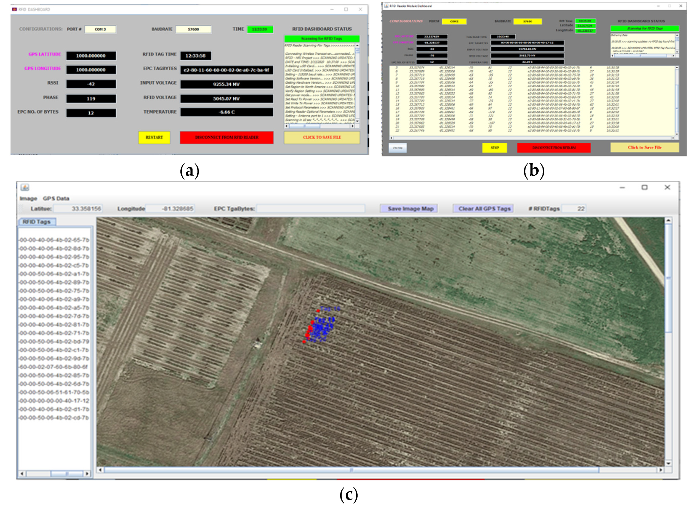
A dashboard was developed to display RFID tag ID, GPS, Received Signal Strength Indicator (RSSI), Phase Angle, and battery information of the RFID-RM. The original dashboard in Figure 4a was developed to display all tag information without a map. The new dashboard in Figure 4b has a view map option button to show the map and the approximate location of the tags. It also has an indicator that the GPS signal is fixed. This information is an indicator that the system is now ready to collect data. Another new feature is the ability to display the approximate location of the tags on a map and the plotting of the reader coordinates in reference to the tag locations (Figure 4c). A logging area is also added to view the count summary of the new tags per pass, and the RFID tag or Electronics Product Code (EPC) Tagbytes are displayed in the order they were scanned. Furthermore, when a user clicks the disconnect button, the data collected are automatically saved in a folder with a timestamped filename.

2.3. Weather Condition

The weather conditions were obtained from the Clemson University- EREC Station Summary of Weather Conditions (www.edistorecweather.net, accessed on 19 August 2021). Table 1 shows the weather report during the data collection.

2.4. The Tag Layout

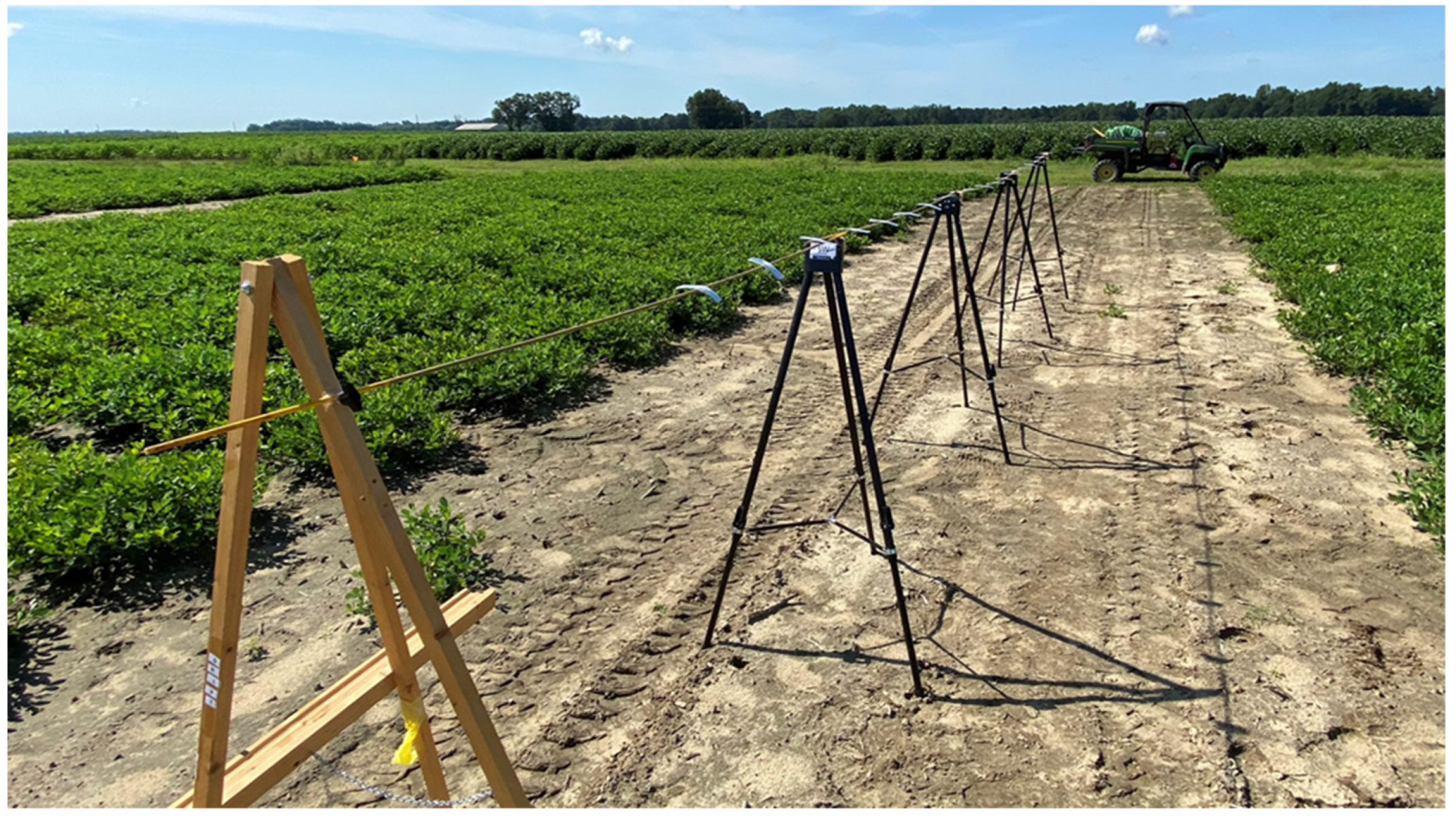
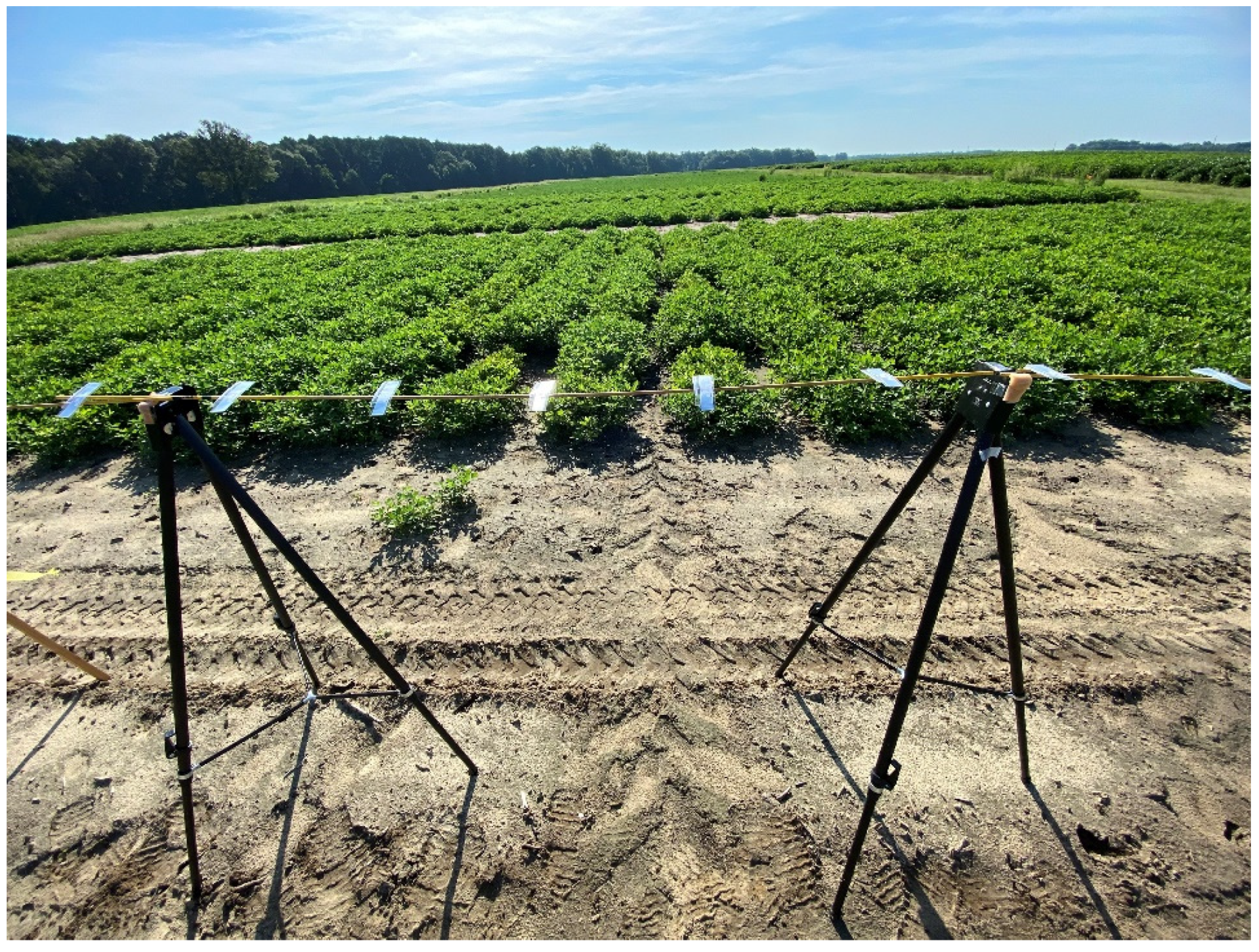
Twenty identical tags were attached to a 1.8-m-long round wood dowel. There were four dowels in total, with six tags attached to the first three dowels and the final two tags on the fourth dowel. The dowel was marked with black stripes to arrange the tags from tag 1 to tag 20. The dowels were placed on top of a tripod stand 1.2 m above the ground. Prior to the drone flights, the dowel was rotated so that the tags face upward due to our previous finding on the best position of the tag. To keep the dowel from rolling, it was placed on top of the foam and taped down. Figure 5 depicts the tags spread sideways by 0.3 m from the center of one tag to the center of the adjacent tag. The total distance measured between tags 1 and 20 was 5.8 m. The spacing of the tags (0.3 m) was based on the normal distance of the pots in nursery production [19].

2.5. The Number of Tags Scanned

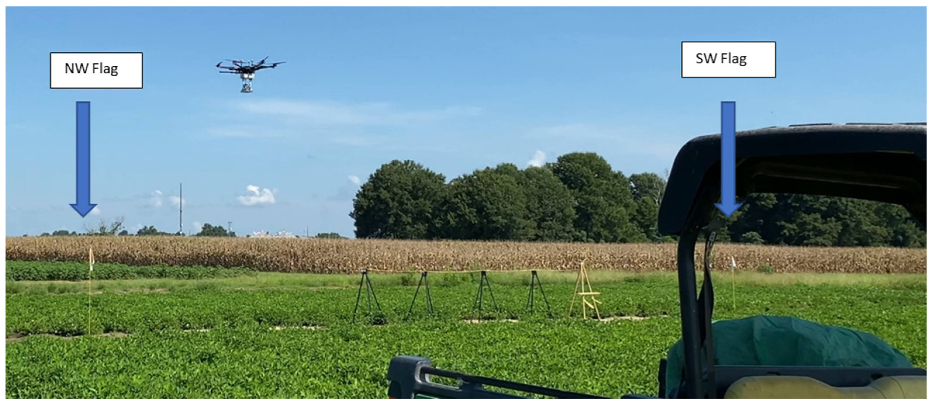
The distance between the drone and the tag was held at 4.5 m. The flight altitude was set to 5.7 m with the tags positioned 1.2 m from the ground. Two flag sticks were used as a guide for the drone flight path. The RFID-RM was attached to the drone with the antenna pointing downward to the tags. Due to the limitations of the drone’s battery, the trips were reduced to three flights per speed to accommodate four trips for a total of eight passes per speed. A single trip consists of two passes, one forward and one backward (Figure 6). Three drone speeds were evaluated; 2.2 m/s (8 kph), 1.7 m/s (6 kph), and 1.1 m/s (4 kph) to compare the scan rate. During the data collection process, some tags were scanned or read multiple times in a single pass, while others were not scanned at all. Tags that are scanned for the first time after being listed in the log area are considered new or unique tags.

2.6. Inverse Rate

Drone travel time and the number of tags scanned were used to determine the inverse rate (seconds per tag [spt]) of each pass. The spt is a value that describes how long it takes to scan a tag in each pass. The drone travel time is the time it will take the drone to travel from tag 1 to tag 20 at a set speed (Equation (1)). As shown in Table 2, the drone travel time is 3.5 s to complete one pass covering 5.8 m at a speed of 1.7 m/s. Consequently, spt was calculated by dividing the number of tags scanned per pass by the drone travel time (Equation (2)).
v = d t
where:
  • ν = drone speed (m/s);
  • d = total distance (meters) flown by the drone in one pass;
  • t = drone travel time (seconds).
    s p t = t T  
    where:
  • spt = seconds per tag;
  • t = drone travel time (seconds);
  • T = new tags scanned per pass.

2.7. RFID-RM Efficiency

To determine the efficiency of the RFID-RM in reading tags at a fixed speed, it is important to determine the distance traveled by the drone to scan the next available tag (meters per tag [mpt]). The mpt is calculated by multiplying the spt with the drone speed (Equation (3)).
m p t = s p t × v
where:
  • mpt = meters per tag
  • spt = seconds per tag
  • ν = speed (m/s)

2.8. Statistical Analysis

A single factor Analysis of Variance (ANOVA) without replication is used to analyze the data. The hypothesis is that the speed of the drone and the number of passes will influence the number of new or unique tag readings.

3. Results

3.1. The Number of New Tags Scanned

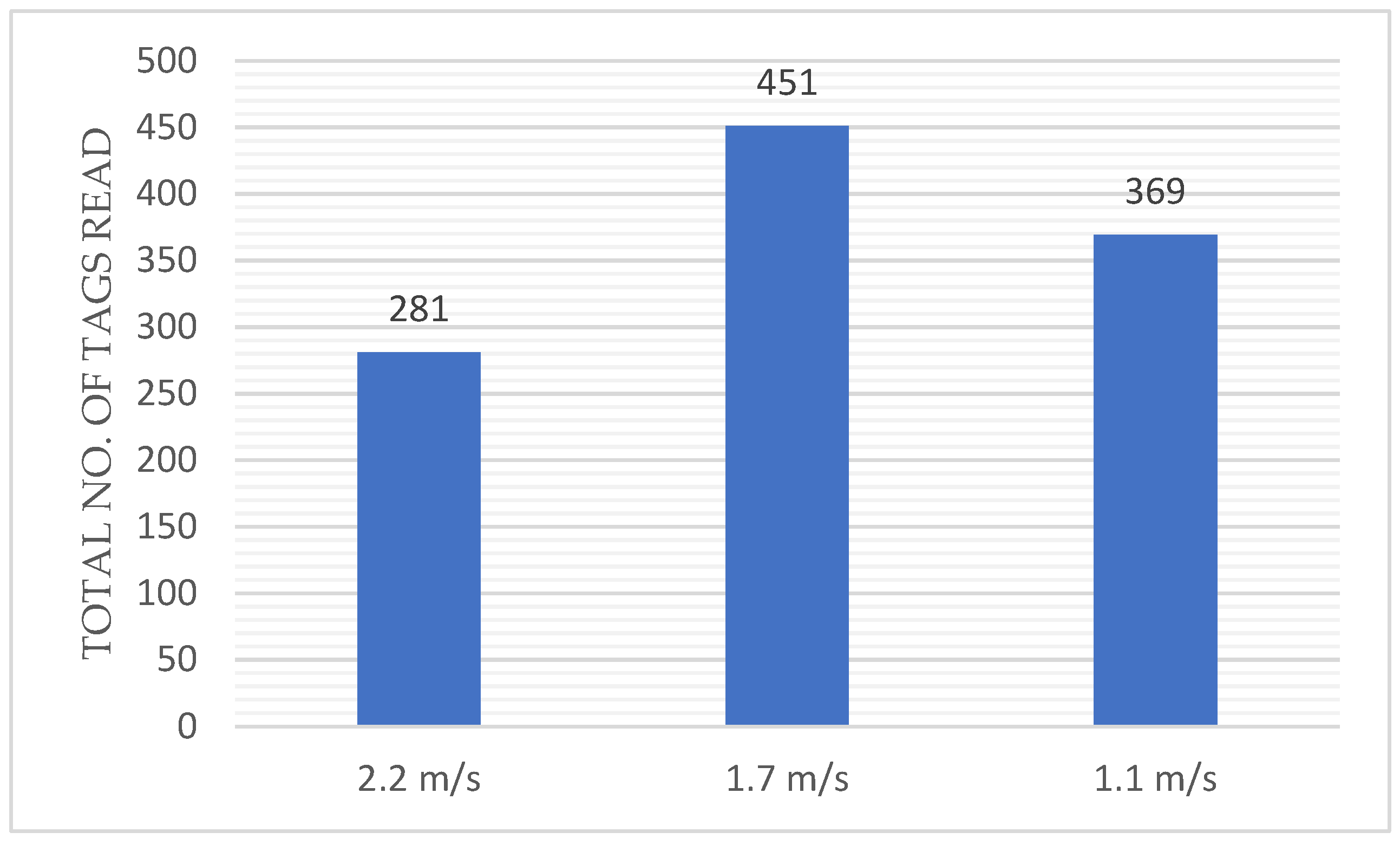
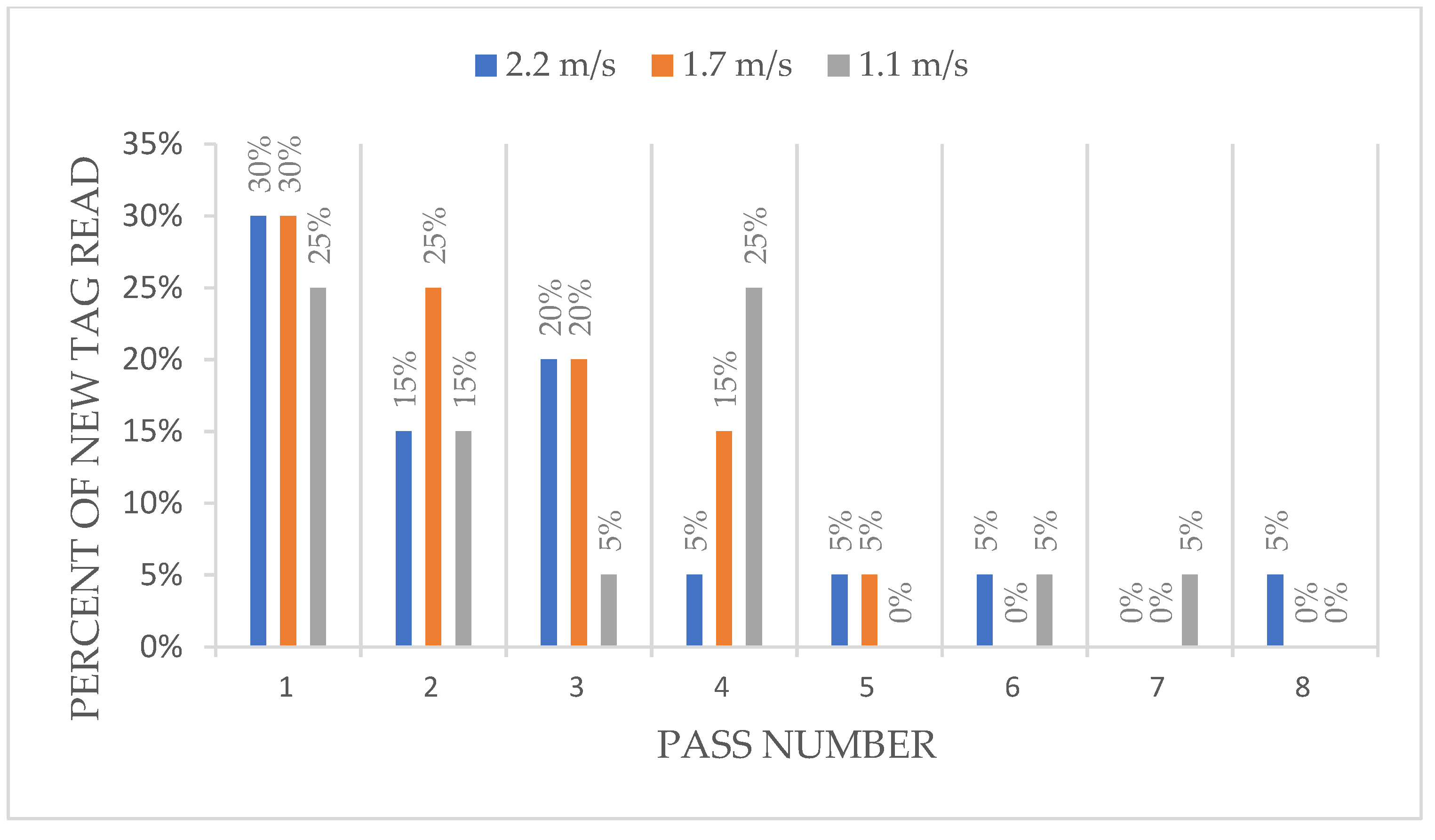
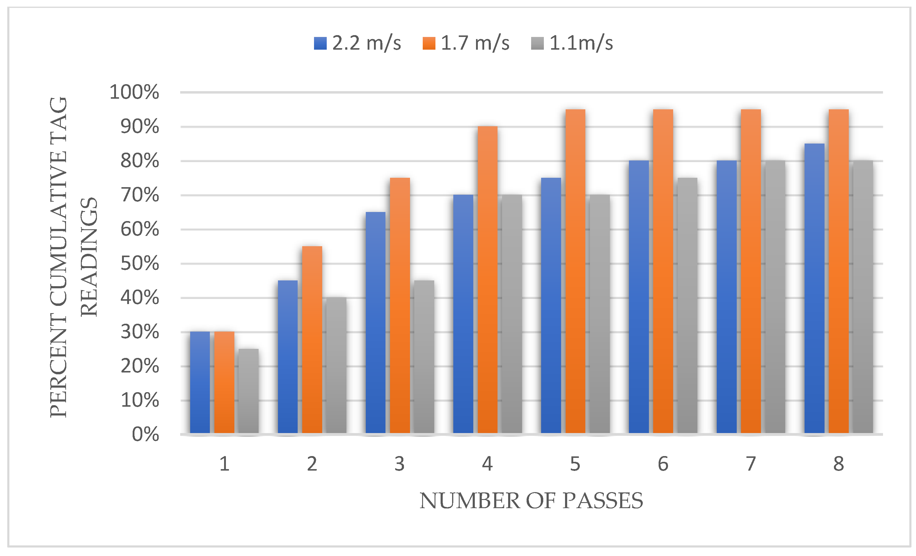
Figure 7 shows the total number of tag readings, which includes tags that have been scanned multiple time as well as newly scanned tags. A forward speed of 1.7 m/s resulted in the greatest number of tags read (451) and 2.2 m/s yielded the fewest (281). Figure 8 shows the percentage of new tags read for each pass based on the three drone speeds. The first pass resulted in the highest percentage of tag read across all three speeds. Values ranged from 25% to 30%. Starting with the fifth pass, the percentage of news tags read never exceeded 5% for any drone speed. In general, across all drone speeds, the percentage of new tags read decreased after the fourth pass. Figure 9 summarizes the cumulative total of tag readings at each pass and at three drone speeds.

3.2. Inverse Rate

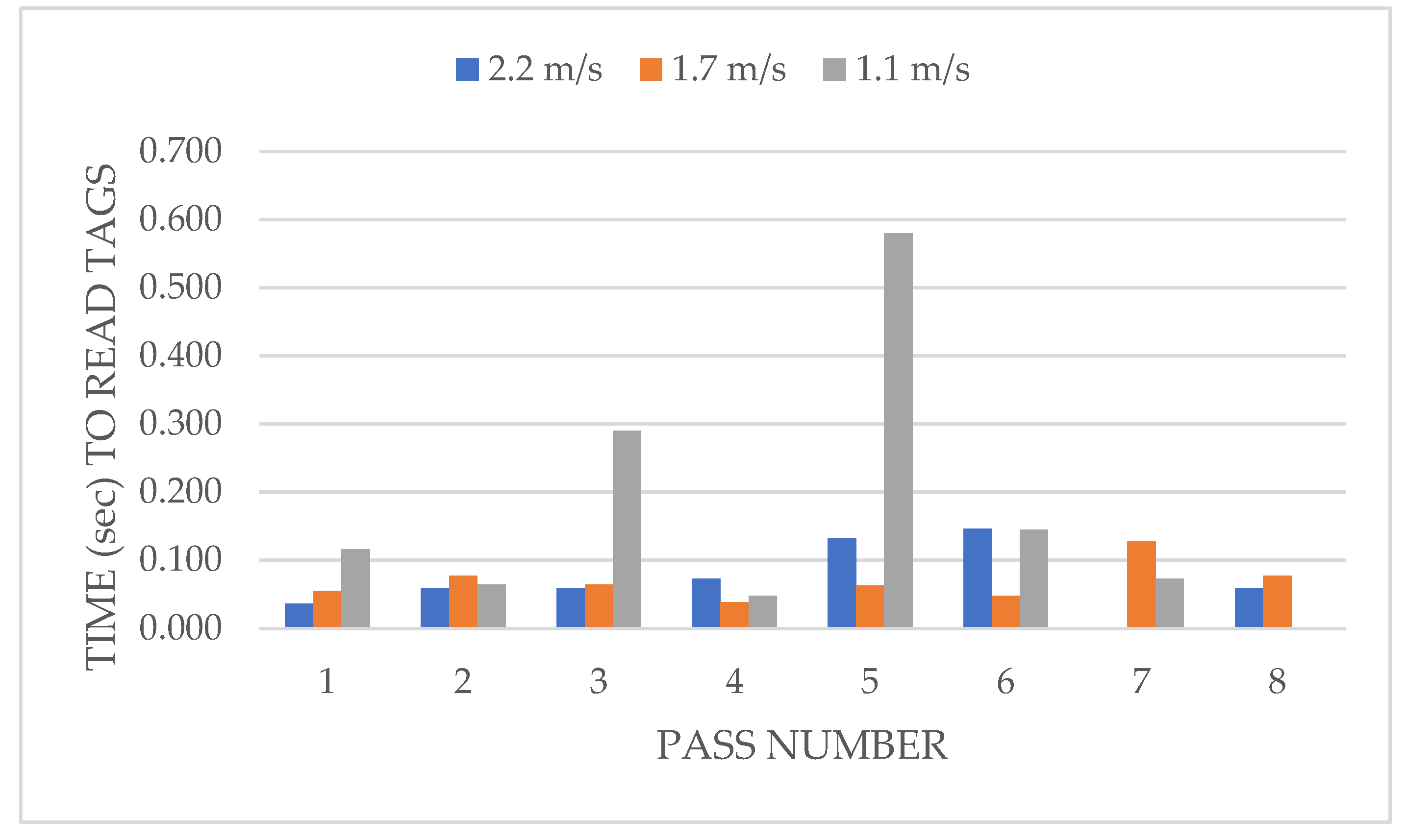
At a speed of 2.2 m/s, the inverse rate ranged from 0 at pass number seven to 0.146 at pass number six as shown in Figure 10. An inverse rate of zero indicates that no tags were read. At a speed of 1.7 m/s, the inverse rate ranged from 0.039 at pass number four to 0.128 at pass number seven. The inverse rate at a speed of 1.1 m/s ranged from 0.048 at pass number four to 0.580 at pass number five.
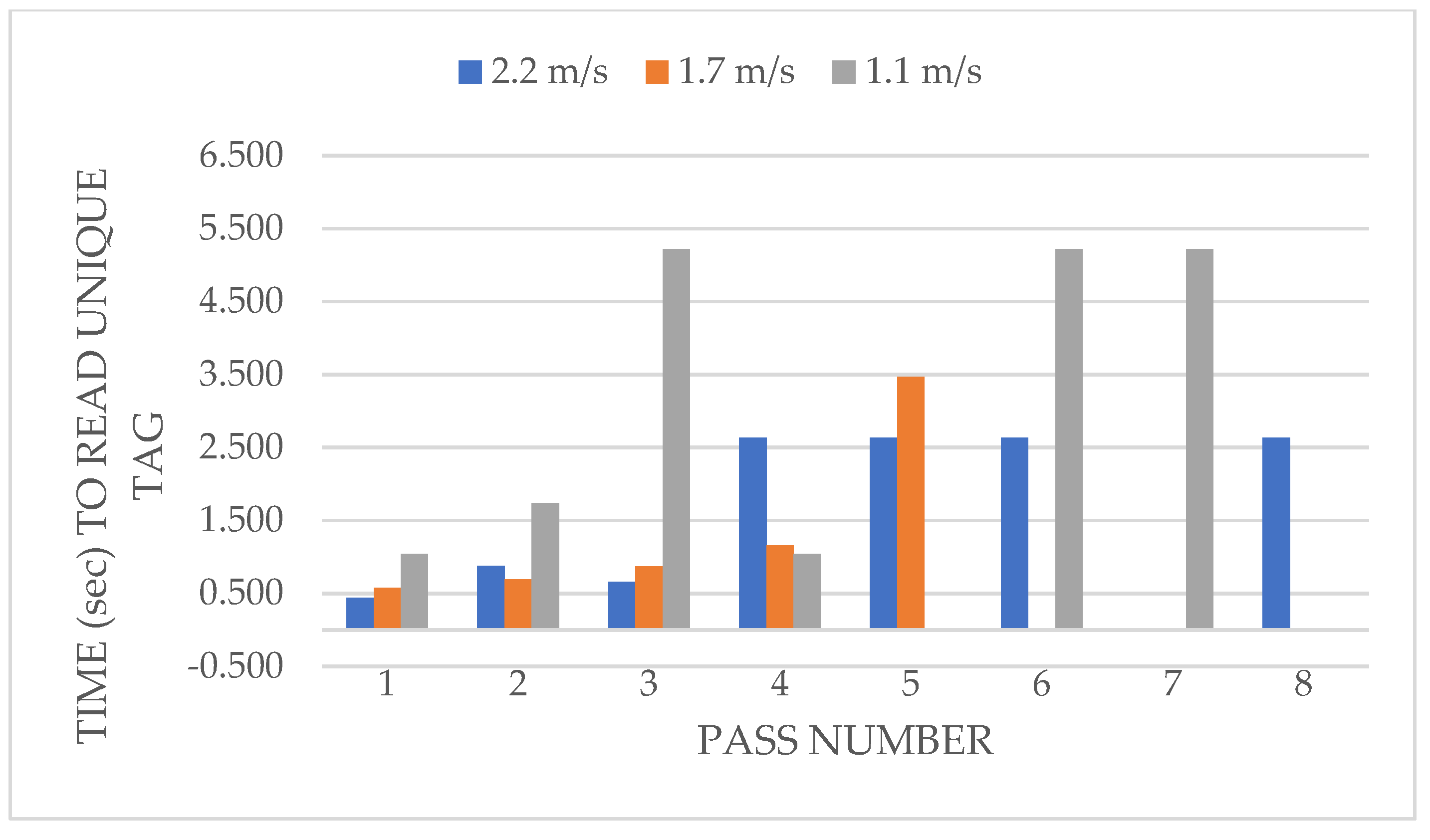
Figure 11 summarizes the effect of drone speed on the number of seconds it takes to read one new tag on each of the eight passes. Results indicate the inverse rate for new tags is between 0.439 at pass number one and 2.632 at pass number four, five, six and seven. At a speed of 1.7 m/s, the inverse rate is between 0.578 at pass number one and 3.467 at pass number five. The inverse rate of 1.1 m/s is between 1.043 at pass number one and 5.216 at pass numbers three, six and seven. Contrary to Figure 10, Figure 11 only shows the unique tag read on multiple passes. Tags which were already read on the first few passes were not counted.

3.3. RFID-RM Efficiency

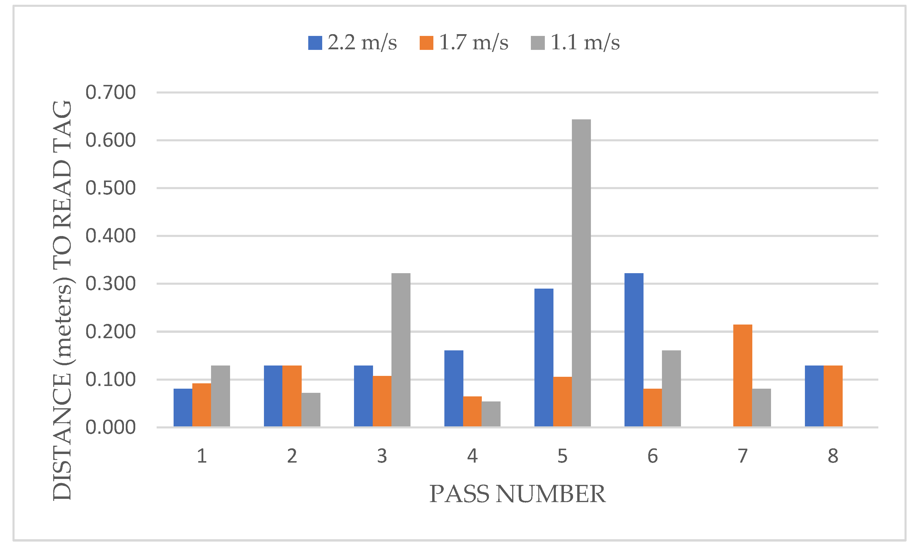
Figure 12 shows that at a speed of 2.2 m/s, the RFID-RM efficiency in terms of readings all tags is between 0.080 at pass number one and 0.322 at pass number six. Furthermore, at a speed of 1.7 m/s, the RFID-RM efficiency is between 0.064 at pass number four and 0.214 at pass number seven. The RFID-RM efficiency of 1.1 m/s is between 0.054 at pass number four and 0.643 at pass number five.
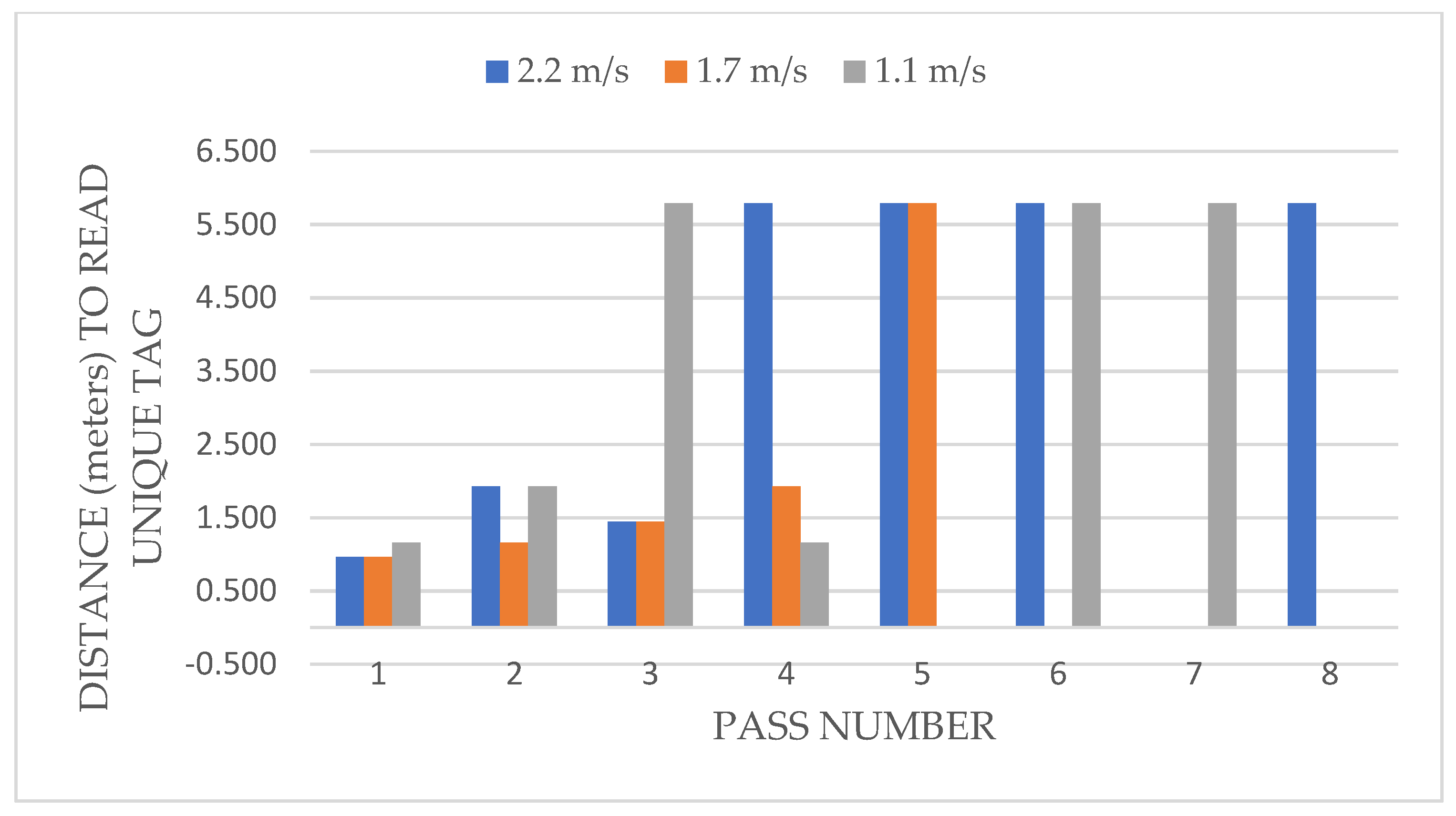
Figure 13 shows that at a speed of 2.2 m/s, the RFID-RM efficiency for unique tags was between 0.96 at pass number one and 5.79 at pass number four, four, six and seven. At a speed of 1.7 m/s, the RFID-RM efficiency is between 0.96 at pass number one and 5.8 at pass number five. While the RFID-RM efficiency of 1.1 m/s is between 1.158 at pass number one and 5.79 at pass number three, six and seven.

3.4. Statistical Analysis

The ANOVA evaluates whether there is a statistically significant difference between each pass reading and how the RFID reader detects tags at variable speeds. The ANOVA parameters are the source of variation, Sum of Squares (SS), degree of freedom (df), Mean Squares (MS), F statistical (F), (p-value) a measure of the probability of the test results gathered on how likely that the same tag readings would occur by random chance, and F critical (F crit). Furthermore, F, p-value, and the F crit values are the values that would determine the significance level of the source of variation. The value F > F crit is the same as p-value < alpha, which rejects the null hypothesis. In this experiment, the source of variation is the number of passes and the drone speeds. The SS, df, MS are values used to compute the F, F crit, and the p-value. The SS is derived by getting the count for each speed reading multiplied by the difference between the speed and grand mean. The grand mean is the average of all the readings, adding the total new tag readings divided by the total count. In addition, the df is the difference between groups minus 1 (8 passes − 1 = 7). The MS is the square of the difference between the mean, and the data collected, while the F results from the mean square of the number of passes divided by the mean square in each pass. The p-value of 0.000126 measures the probability that an observed difference could occur is computed using F, df between groups as the numerator and df within groups as the denominator. F crit is computed using three arguments, the alpha value, numerator df between groups (between each pass), and the denominator df within each pass.
The number of passes made by drone scanning new/unique tags has an influence on the number of tags read (p-value = 0.000126); however, the three speeds used for this experiment are not significant (p-value = 0.941182) (see Table 3).

4. Discussion

Prior to these experiments, the hypothesis was that the speed of the drone and the number of passes has an influence on the reading of unique or new tags. Results from our experiments suggest that only the number of passes will affect the number of new tags read. At 2.2 m/s, the label scanning is between 0.037 and 0.146 spt. At 1.1 m/s the label scanning is between 0.048 and 0.580 spt. The result also shows that the total time required to collect tag information is determined by the drone’s speed and the length of the flight path [20,21]. In addition, at speeds of 1.1 to 2.2 m/s, the scan time ranged from 0.01 to 0.15 has a common overlap. Based on our results, the effect of the number of readings when the drone changes speed is not significant.
Furthermore, the first pass results in the highest percentage of new tags scanned across all speeds. On the fifth pass, the scan rate begins to drop. However, 1.7 m/s scanned a total of 95 percent of new tags on the fifth pass, the highest percentage among the three speeds. The scan rate trend increases from the first to the fourth pass and then a decreasing trend from the fifth to the eighth pass. In addition, after the scan rate reaches 70% of the tags scanned, the scan rate also shows a decreasing trend. The decreasing trend was since only 30% of new tags are still available for reading.
There were instances where readings were not reported, starting at the pass 5 onwards. In Figure 9, no readings were recorded at a drone speed of 2.2 m/s for pass 7 and 1.1 m/s for pass 8. Figure 10 also shows that at pass 5, at the speed 1.1 m/s did not register any readings, but readings were registered on passes 6 and 7. The same instances can be found in Figure 11 and Figure 12, where no readings were registered at various speeds. This could be attributed to how the RFID-RM is responding to tag readings. Every tag read goes into an interrupt service routine where it collects all available information before the reader will be available for reading another tag. Although the tags are of the same manufacturer, some tags may respond quicker and thus create multiple instances of the interrupt, thus, delaying the reader. Moreover, the physical constraints feature of radio frequency poses a barrier to advanced anti-collision techniques for RFID chips, due to the interference from the transition signal’s scattering and reflection [22].
We presented two novel measurements on evaluating RFID reader efficiency by measuring how fast the reader can read and the shortest distance traveled of the RFID reader reading a tag. These two measurements can be used to compare other RFID readers developed by different manufacturers.

5. Conclusions

Based on results from this experiment, the first three flights have the highest number of unique tags scanned. The time required to scan tags repeatedly is 0.04 s per tag (spt), and the minimum distance is 0.064 m per tag (mpt) at a speed of 1.7 m/s. New tags can be scanned in the first five passes at a percentage between 70 to 95 percent. The first pass results in the most readings (30%), and gradually decreases as the number of passes increases. The decline is attributable to a reduction in the quantity of new scannable tags.
Finally, when scanning new tags, the pass number is essential. At least two flights equivalent to four passes will get a scan rate of 70% to 90%. It takes 0.578 to 3.467 spt to scan at a speed of 1.7 m/s with a minimum distance of 0.96 mpt. It is important to note that due to the placement of plants in the field at close proximity, this experiment showed that the drone must perform multiple passes on the same location to gather an accurate inventory. This limitation has been shown in the results of this work. The distance of the tags was based on the distance between the pots in a real nursery production.
This technology is a potential tool in obtaining automated, aireal based nursery inventory data that would reduce labor hours in the field for data retrieval. Once the pandemic has subsided, we will conduct the field testing in large nurseries.

Author Contributions

Conceptualization, J.M.M. and J.Q.; methodology, J.Q.; software, J.N.C. and J.Q.; validation, J.Q.; formal analysis, J.Q.; investigation, J.Q.; resources, J.M.M., J.R., J.O.J., R.T.F. and M.C.; data curation, J.Q.; writing—original draft preparation, J.Q., J.M.M. and J.R.; writing—review and editing, J.M.M., J.R., J.O.J., R.T.F. and M.C.; visualization, J.Q.; supervision, J.M.M.; project administration, R.T.F.; funding acquisition, R.T.F., J.M.M., J.R., J.O.J. and M.C. All authors have read and agreed to the published version of the manuscript.

Funding

This research was partially supported by Horticultural Research Institute (HRI) Grant number 5935985 and is based on work supported by NIFA/USDA under project numbers MICL02473, and SC-1700609.

Data Availability Statement

Not applicable.

Acknowledgments

The authors would like to thank Avery Dennison Corporation and R.A. Dudley Nurseries Inc. for their support and assistance in this project.

Conflicts of Interest

The authors declare no conflict of interest.

References

  1. USDA NASS. US Farmers Expect to Plant More Corn and Soybean Acreage. 2021. Available online: https://www.nass.usda.gov/Newsroom/2021/03-31-2021.php (accessed on 9 July 2021).
  2. USDA NASS. U.S. Horticulture Operations Report $13.8 Billion in Sales. 2019. Available online: https://www.nass.usda.gov/Newsroom/archive/2020/12-08-2020.php (accessed on 23 September 2021).
  3. Hall, C.R. Managing Plant Material Inventory. Ornamental Production. 2021. Available online: https://aggie-horticulture.tamu.edu/ornamental/economic-fact-sheets/managing-plant-material-inventory/ (accessed on 29 June 2021).
  4. West, B. Nursery Inventory Management. Lawn and Landscape (Market Leadership). 2020. Available online: https://www.lawnandlandscape.com/article/nursery-inventory-management (accessed on 18 May 2021).
  5. Owen, J.S.; Lebude, A.; Calabro, J.; Boldt, J.; Gray, J.; Altland, J. Research Priorities of the Environmental Horticultural Industry Founded through Consensus. J. Environ. Hortic. 2019, 37, 120–126. [Google Scholar] [CrossRef]
  6. Abayomi, E.J.; Ridolfo, H. The Effects of Currently Reported Data on Data Quality: An Analysis of the Agricultural Labor Survery. 2017. Available online: https://www.nass.usda.gov/Education_and_Outreach/Reports,_Presentations_and_Conferences/reports/conferences/JSM/JSM_2017_Abayomi-Ridolfo.pdf (accessed on 18 May 2021).
  7. de Castro, A.; Maja, J.M.; Owen, J.; Robbins, J.; Pena, J. Experimental approach to detect water stress in ornamental plants using suas-imagery. Proc. SPIE 2018, 10664, 106640N. [Google Scholar] [CrossRef]
  8. Ehsani, R.; Maja, J. The Rise of Small UAVs in Precision Agriculture. 2013. Available online: https://elibrary.asabe.org/pdfviewer.asp?param1=s:/8y9u8/q8qu/tq9q/5tv/HH/72IGHJ/IG/K/hBIG_K_HO.5tv&param2=L/IK/IGIH&param3=HJG.HIN.ILL.IGJ&param4=44296 (accessed on 28 May 2021).
  9. Bowman, K.D. Identification of Woody Plants with Implanted Microchips. Am. Soc. Hortic. Sci. 2005, 15, 352–354. [Google Scholar] [CrossRef]
  10. Ampatzidis, Y.; Vougioukas, S. Field Experiments for evaluating the incorporation of RFID and barcode registration and digital weighing technologies in manual fruit harvesting. Comput. Electron. Agric. 2009, 66, 166–172. [Google Scholar] [CrossRef]
  11. Luvisi, A.; Panattoni, A.; Bandinelli, R.; Rinaldelli, E.; Pagano, M.; Gini, B.; Triolo, E. RFID microchip internal implants: Effects on grapevine histology. Sci. Hortic. 2010, 124, 349–353. [Google Scholar] [CrossRef] [Green Version]
  12. Luvisi, A.; Pagano, M.; Bandinellie, R.; Rinaldelli, E.; Gini, B.; Scarton, M.; Triolo, E. Virtual vineyard for grapevine management purposes: A RFID/GPS application. Comput. Electron. Agric. 2011, 75, 368–371. [Google Scholar] [CrossRef]
  13. Kumagai, M.H.; Miller, P. Development of electronic barcodes for use in plant pathology and functional genomics. Plant Mol. Biol. 2006, 61, 515–523. [Google Scholar] [CrossRef] [PubMed]
  14. Ampatzidis, Y.; Vougioukas, S.; Bochtis, D.; Tsatsarelis, C. A yield mapping system for hand-harvested fruits based on RFID and GPS location technologies: Field testing. Precis. Agric. 2008, 10, 63–72. [Google Scholar] [CrossRef]
  15. About-RFID. Available online: https://www.impinj.com/about-rfid/types-of-rfid-systems#:~:text=Passive%20RFID%20systems%20can%20operate,typically%20less%20than%2010%20m (accessed on 10 November 2020).
  16. Fernandez, R. RFID: How It Works and What It Can Do for the Green Industry. Am. Hort Newsl. 2014, 9, 6–11. Available online: https://www.researchgate.net/publication/271194305_RFID_How_It_Works_And_What_It_Can_Do_For_The_Green_Industry (accessed on 8 September 2020).
  17. Quino, J.; Maja, J.; Robbins, J.; Fernandez, R.; Owen, J.S.; Chappell, M. RFID and drones: The next generation of plant inventory. AgriEngineering 2021, 3, 168–181. [Google Scholar] [CrossRef]
  18. Saraswat, D.; Robbins, J. High-Tech Tags. Nursery Management. 2011. Available online: https://www.nurserymag.com/article/nm1111-rfid-technology-tags/ (accessed on 28 May 2021).
  19. R.A. Dudley Nurseries, Inc. Available online: https://www.radudley.com/plants-archive (accessed on 23 September 2021).
  20. Buffi, A.; Motroni, A.; Nepa, P.; Tellini, B.; Cioni, R. A SAR-based measurement method for Passive-Tag positioning with a Flying UHF-RFID Reader. IEEE Trans. Instrum. Meas. 2019, 68, 845–853. [Google Scholar] [CrossRef]
  21. Siachalou, S.; Megalou, S.; Tzitzis, A.; Tsardoulias, E.; Bletsas, A.; Sahalos, J.; Yioultsis, T.; Dimitriou, A.G. Robotic Inventorying and Localization of RFID Tags Exploiting Phase-Fingerprinting. In Proceedings of the 2019 IEEE International Conference on RFID Technology and Applications (RFID-TA), Pisa, Italy, 25–27 September 2019; pp. 362–367. [Google Scholar] [CrossRef]
  22. Yang, P.; Wu, W.; Moniri, M.; Chibelushi, C.C. Efficient Object Localization Using Sparsely Distributed Passive RFID Tags. IEEE Trans. Ind. Electron. 2013, 60, 5914–5924. [Google Scholar] [CrossRef]
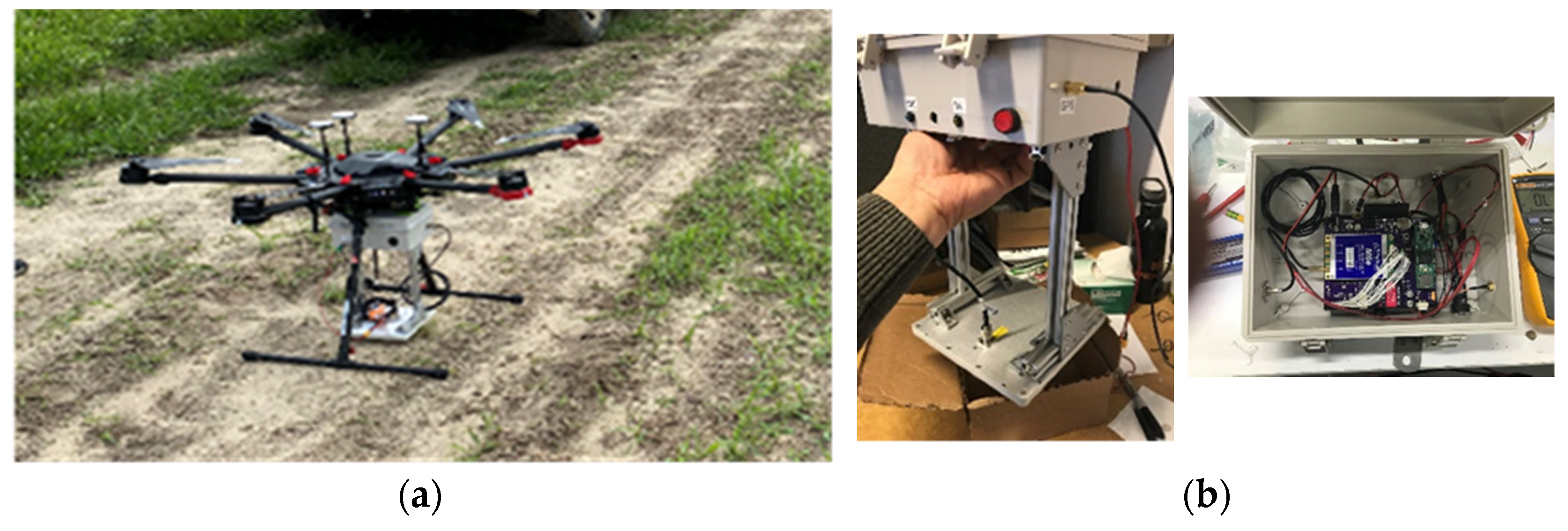
Figure 1. (a) DJI Matrice 600 Pro, and (b) RFID Reader Module (RFID-RM).
Drones 06 00002 g001
Figure 2. The RFID tag design (Avery Dennison Corp., Glendale, CA, USA) used in the experiment.
Drones 06 00002 g002
Figure 3. RFID tags at the study site facing upward.
Drones 06 00002 g003
Figure 4. The (a) old Dashboard version, (b) new version of the Dashboard, and (c) Map showing the approximate location of the different RFID tags in the field.
Drones 06 00002 g004
Figure 5. The tags spaced at 0.30 m, facing upward.
Drones 06 00002 g005
Figure 6. Drone flying at 5.7 m AGL toward the tags.
Drones 06 00002 g006
Figure 7. The effect of drone speed on the number of total tags reading (includes multiple reads per tag).
Drones 06 00002 g007
Figure 8. Percent of new tags read at three speeds of the drone for eight passes.
Drones 06 00002 g008
Figure 9. The cumulative tag readings in each pass at three drone speeds.
Drones 06 00002 g009
Figure 10. The number of seconds per tag (inverse rate) for each pass and each drone speed as calculated using Equation (2).
Drones 06 00002 g010
Figure 11. The time required to read each new tag for each pass at three drone speeds.
Drones 06 00002 g011
Figure 12. The distance covered to read tag for each pass as calculated using Equation (3).
Drones 06 00002 g012
Figure 13. The distance covered to read unique tag for each pass at three different speeds.
Drones 06 00002 g013
Table 1. Clemson University-EREC Station Summary of Weather Conditions.
Wind Speed4.8 kph~9.7 kph
Average Wind Speed1.4 kph~4.5 kph
Predominant Wind SpeedNE, E, ENE
Humidity Level78.8~85.2%
Temperatures28.3~30.7° Centigrade
Atmospheric Pressure101,998.0~102,028.5 Pa
Table 2. Drone travel time per pass.
Speed (v)
Meters per Sec
Total Distance (d)
Meters
Drone Travel Time (t)
Seconds
2.2 m/s (8 kph)5.82.6
1.7 m/s (6 kph)5.83.5
1.1 m/s (4 kph)5.85.2
Table 3. Anova results for scanning a new/unique tag.
Source of VariationSSdfMSFp-ValueF Crit
No. of Passes81.3711.69.30.0001262.7
Drone Speeds0.620.30.10.9411823.5
Publisher’s Note: MDPI stays neutral with regard to jurisdictional claims in published maps and institutional affiliations.