1. Introduction
Waste disposal technology has improved significantly in the United States (US) and Western Europe over the past half century. Disorderly waste storage in open dumps has been replaced by modern landfill disposal technology. The main provisions of a managed landfill concept have been incorporated into European Union (EU) and US legislation and, currently, most of their waste disposal sites (WDSs) operate in accordance with well-developed technological regulations under the strict supervision of state regulatory authorities [
1]. At the same time, this means that while the severity of the problem with the impact of WDSs on the environment has decreased, the problem of monitoring the WDS operation remains urgent.
On the other hand, there are developing countries in which the vast majority of waste goes to landfills and the technology for WDS management is at a rather low level of sophistication. Accordingly, the effective technological solutions in WDS monitoring and control are also relevant for these countries [
2].
The most common practice of technological landfill monitoring is ground inspections. At the same time, the development of remote monitoring methods has long been of interest, as they save time and labor resources, and reduce the risks for personnel when inspecting hazardous areas of facilities.
The first attempts to use aerial imagery to study dumps and landfills date back to the 1970s. They were led by the US, which launched a program for a WDS survey. This was facilitated by the adoption of the Resource Conservation and Restoration Act (1976) and the Comprehensive Environmental Responsibility, Compensation and Liability Act (1980), according to which all WDSs were required to undergo an inventory assessment and have an established owner, and abandoned WDSs were to be eliminated if they were identified as sources of accumulated environmental damage. As a result, methodological and procedural frameworks were developed for the use of aerial imagery for WDS inventory and classification [
3,
4,
5]. The methodology has been successfully tested in the field [
5]; surveys of vast territories were carried out in order to identify unauthorized dumps [
6].
Aerial imagery was performed at the operating WDS for detailed topographic mapping, in order to determine the area of the landfill, the volume of disposed waste, the degree of the facility’s waste filling, and other spatial characteristics [
7]. Aerial imagery proved to be useful, not only for determining the geometric characteristics of the waste mass, but also for assessing the order of waste storage, types of waste, location of liquid waste disposal, and other aspects [
7,
8].
It was pointed out that detailed topographic mapping of the WDS and adjacent territories makes it possible to identify potential pathways for the migration of pollutants into water [
9]. Many researchers noted that the key to success in finding migration pathways for landfill leachate was the identification of negative landforms on aerial images such as ravines [
10], geological faults and surface cracks [
7], abandoned drainage systems, etc.
Accordingly, it has been proved that aerial survey data are essential for the selection of monitoring points for surface and ground water [
5].
Since the 1990s, manned aerial imagery has largely given way to space imagery in the field of waste management. The increase in availability, quality and detail of satellite images has led to the fact that aerial imagery of WDSs via manned aircrafts, due to its relatively high unit cost, has become very limited.
Summing up the current stage of development and the implementation of aerial imagery technology in waste management practices, it can be noted that the subjects of aerial imagery were mainly illegal dumps, and the remote survey methods, for all their usefulness, were assigned to an auxiliary role. The latter fact was largely determined by the underdevelopment of technology for the processing of aerial photographs. Insufficient automation of image processing, lack of knowledge databases, and the methodological problems of remote monitoring prevented researchers from recommending aerial imagery for wide practical use by landfill operators [
10].
However, about a decade ago, revolutionary changes were made in the field of remote sensing technology, which were associated with the rapid development and spread of unmanned aerial imagery technology and photogrammetric technology for the processing of aerial photographs that were obtained from unmanned aerial vehicles (UAVs). Following construction, engineering surveys and mine surveying, drones took their place in the field of waste management; according to reports in press and scientific literature, they were first used to search for illegal dumps [
11,
12], for the topographic mapping of WDSs [
13], for the planning of environmental protection measures at landfills [
14], as well as for the monitoring of separate technological processes at landfills, such as storage, compaction and intermediate isolation of waste [
15]. Thus, it was shown that UAVs are capable of completing the entire range of tasks that are associated with the monitoring of landfills, and that they are superior to manned vehicles in such parameters as simplicity, efficiency and survey cost.
At the same time, the boundaries of drone use for landfill management remained unclear. Researchers often focused on certain aspects of WDS monitoring, such as the calculation of the amount of stored waste [
16,
17], the source identification of landfill gas emissions [
18,
19], the study of landslide processes [
20,
21], etc. To study these aspects, in many cases, required the use of some relatively expensive sensors for UAVs, such as air laser scanners, thermal imaging cameras, multispectral cameras, gas detectors, etc. The question of the extent to which a low-cost UAV that is equipped with a “conventional” RGB camera can help to ensure the correct operation of a landfill, until recently, has not been covered in detail.
In the scientific articles of the last decade that pertain to the use of UAVs for waste management, the issues of remote technological monitoring of waste landfills are rarely touched upon [
16,
22].
Even the appearance of the specialized geoplatforms for processing aerial imagery data, which were considered as a means of monitoring waste landfills [
23,
24], did not lead to the development of algorithms for the interpretation of photographic images. The issues of interpreting aerial imagery materials through these geoplatforms were still dependent on the experience, professionalism, knowledge base and subjective views of the operator.
This work was aimed at assessing the extent to which the control of compliance with technological standards for the operation of modern landfills can be carried out through unmanned aerial imagery. At the same time, what is perhaps the simplest and most affordable method was included among the unmanned aerial imagery methods, that is, aerial imagery via a low-cost UAV using a standard RGB (Red, Green, Blue) camera.
The use of sensors such as multispectral or thermal imaging cameras, air laser scanners, gas detectors, etc., which can also be useful for monitoring WDSs, are not covered in this article.
At the same time, one of the priorities of this study was the development of the methodological foundations of such remote monitoring; this included the preparation of a set of guidelines for the processing and interpretation of aerial imagery materials, on the basis of which the operator could detect problems in the WDS operation and plan measures to correct them.
The solution to this problem will allow us to more accurately determine the boundaries of UAV applicability in the field of waste management and will contribute to the wider introduction of remote monitoring methods into the practice of managing such complex systems as waste landfills.
2. Materials and Methods
In order to study the opportunities that UAVs provide for technological monitoring of operated landfills, 12 dumps and landfills of the Perm Region and the Sverdlovsk Region (Russia) were examined between 2017 and 2021.
Along with the currently operating landfills, it was also considered useful to survey a number of dumps that were mostly closed, but not reclaimed, as their example could be used to work out algorithms for solving a number of problems that are relevant to landfills (for example, the search for landfill leachate leakages).
Basic information about the studied WDS is given in
Table 1.
The main factors that determined the choice of the UAV for WDS monitoring were: (1) the relatively small size of the monitoring objects; (2) the need to reduce the cost of the monitoring complex. Since the size of the majority of WDSs do not exceed several tens of hectares, then, even when taking into account the need to monitor the adjacent territory, it can be concluded that the optimal UAV type for WDS monitoring is a multicopter. Scientific literature mentions that the advantages of a multicopter (high maneuverability, efficiency of deployment and launch, etc.) in comparison with an aircraft-type UAV are maximally optimized when surveying territories with an area of up to 1–2 km
2, and can be used to survey areas of up to 5 km
2 [
25]. On the contrary, the advantages of an aircraft-type UAV (higher performance and flight range) in such cases have almost no effect. Considering these conditions, the significantly lower cost of multicopters in comparison with aircraft UAVs of a similar class is of decisive importance when choosing equipment.
For aerial imagery, UAVs of a multi-rotor type were used—low-cost quadrotors of the DJI Phantom series (DJI Phantom 3 Pro, DJI Phantom 4 and DJI Phantom 4 Pro). Engineering samples of quadrotors were also tested based on ArduPilot software, Pixhawk 2 flight controllers and Ublox NEO-M8P-2 receivers using the global navigation satellite system (GNSS) with the support of the real time kinematics (RTK) mode, thereby providing sub-decimeter positioning accuracy of the apparatus. The engineering UAVs used Sony DSC-RX1R, Sony DSC-RX100 and Olympus Pen E-PL6 cameras as sensors. The flights were planned in DroneDeploy (for DJI Phantom UAV) and Mission Planner (for engineering UAV) software.
There are several works by Thai and Korean researchers in which the issues of choosing the optimal parameters of the flight task for aerial imagery of landfills and dumps are considered in detail [
26,
27,
28,
29]. On the one hand, the experience of these researchers was taken into account when planning flights (in particular, when choosing the required value of the survey resolution on the ground—the ground sample distance, GSD parameter); on the other hand, it was also taken into account that this study required a relatively lower accuracy of aerial imagery since no tasks were set for the high-precision mapping of objects for their geodetic monitoring.
These surveys were carried out, whenever possible, using ground control points, which were installed at the rate of at least five per object and at least 1 per 2 hectares of the survey area. The coordinates of the ground-control-point centers were determined using high-precision geodetic receivers that used the global navigation satellite system (GNSS). The measurement accuracy was checked at several (at least three) of the nearest triangulation points.
The use of ground control points for technological monitoring purposes is not strictly mandatory, but nevertheless, it is very useful when comparing the results of aerial imagery at different times (georeferenced landfill models can be much more accurately combined with each other in the environment of geographic information systems (GIS)).
Basic information on planning and conducting flights is presented in
Table 2.
The weather conditions during the aerial imagery were quite varied; thus, the UAVs were operated at temperatures from –9 °C to +32 °C. In accordance with the requirements in the UAV-operating manuals, flights were not carried out at a wind speed of more than 10 m/s (for flight safety) and during periods of precipitation (to prevent loss of image quality).
The aerial imagery data was processed in several stages and analyzed. The preliminary processing of aerial photographs was carried out in the graphics editor Adobe Lightroom Classic and consisted of adjusting the overall exposure of the images, improving the clarity of images, noise reduction, etc. The expediency of the preliminary preparation of aerial photographs has already been noted in the literature [
30].
Data processing included two stages: (1) the photogrammetric processing of images with the receipt of final processing products—a georeferenced orthophotoplan and a three-dimensional polygonal model, textured with aerial photographs; (2) the thematic interpretation of the final images in accordance with the objectives of the study.
Photogrammetric data processing was carried out in the Agisoft Metashape Pro 1.5.0 software according to the instructions of the software manual. The resulting orthophotoplans and 3D models provided the necessary overview of the WDS facility and made it possible to obtain a holistic view on the state of separate engineering systems throughout the facility.
Thematic interpretation of the final images and models was carried out using checklists, which listed the norms and requirements for the landfill operation. The lists were formed on the basis of the national legislation that governs the operation of landfills. However, in this study, in addition to Russian legislation, foreign regulatory legal acts that contain requirements for waste landfills were analyzed.
Thus, in the countries of the European Union, the main document that regulates the basic requirements for the arrangement and operation of landfills is the Council Directive 1999/31/EC [
31]. In the United States, the framework requirements for landfills are established by the aforementioned Resource Conservation and Recovery Act [
32]. In Russia, the operation of municipal solid waste (MSW) landfills is regulated by a set of rules SP 320.1325800.2017 [
33]. After the analysis of these regulations, we identified four groups of requirements that were reflected in all three documents, which cover a significant part of the issues related to landfill operation, and compliance with which, presumably, could be a function of remote monitoring:
Intermediate waste containment;
Protection of adjacent territories from pollution and littering;
On-site technical infrastructure;
Ensuring stability of the waste mass.
In the course of the surveying of landfills, the possibility of the remote technological monitoring of compliance with each of these groups of requirements was tested.
In order to clarify the data on the problem areas of the WDSs, in addition to the orthophotoplan, separate aerial photographs with the image of a specific area were viewed. In some cases, in order to check the correctness of the thematic interpretation of the results of aerial imagery, selective field surveys of the WDSs were repeated. Thematic decryption of ground surveys and images were carried out by the authors of this work with the participation of employees (personnel) of the surveyed landfills.
3. Results and Discussion
In this section, we focus on examples where a simple visual analysis of images that were obtained with an RGB camera allows us to assess the fulfillment of the requirements for the landfill operation.
3.1. Intermediate Waste Containment
These requirements can be formulated either directly, as in a layer-by-layer alternation of dumped waste and inert non-combustible materials (for example, soil [
32,
33]), or indirectly, as in measures to prevent waste ignition, the spread of waste, smells, dust or pathogens, etc. [
31]. In addition, the timely containment of the landfill slopes significantly increases its stability.
Unmanned aerial imagery allows the control of the implementation of an intermediate insulating cover on the landfill.
Figure 1 shows the containment of MSW with soil at the MSW landfill “S” in the Perm Region, Russia. Areas with a newly laid soil layer (circled in red) are clearly visible and stand out against the background of fresh waste. Images of areas with an old insulating layer, which was laid about a year ago (circled in yellow), are also interpreted; they clearly show the elaborated channels of small streams and traces of surface runoff.
Satellite imagery also allows the tracking of intermediate waste containment, but it is significantly less efficient than unmanned aerial imagery, which makes a difference for the timely control of this technological process which, according to the standard requirements, should be carried out at least once every few days.
3.2. Protection of Adjacent Territories from Pollution and Littering
The contamination and littering of the adjacent territory and access roads is one of the first aspects to be taken into account when assessing the impact of the WDS on the environment. All of the considered regulatory documents stipulate the unacceptability of the waste contamination of adjacent territories.
Waste spreads from the WDS by wind, water and, to a smaller extent, by animals. The main preventive measure for this is timely intermediate waste containment. It is also important to store waste properly and strictly within the designated disposal maps, in accordance with the scheme for filling the landfill. In some cases, other measures and means may be helpful, such as portable mesh fences.
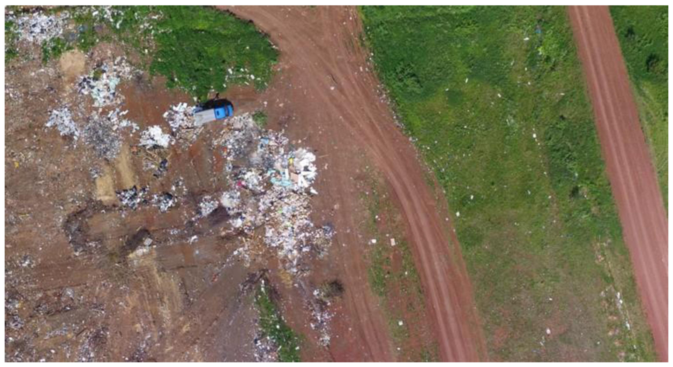
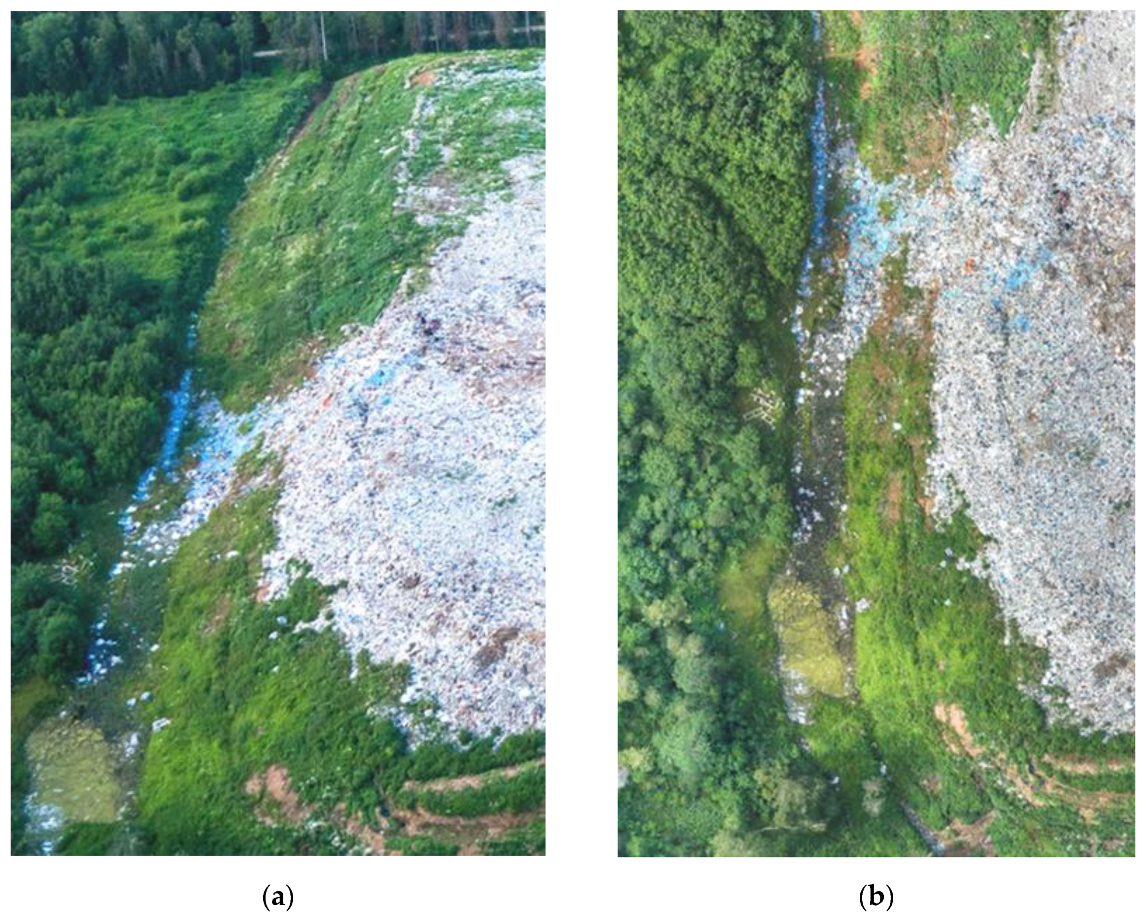
Unmanned aerial imagery is very effective for identifying and assessing diffuse waste pollution in the surrounding area, which happens when light fractions of waste are spread by wind and surface waters.
Figure 2 shows a fragment of the territory adjacent to the small MSW dump “I” in the Perm Region, Russia. The contamination of the surrounding area (the area between two earth roads in the right part of the image) with spread waste is clearly visible. Contamination is recognized by the distinctive white dots or spots that are distributed over the survey area, with their accumulations in the area of relief depressions (for example, roadside ditches, as in the given image). The aerial imagery here has a significant advantage over space imagery due to its detail. Such contamination, even with ultra-high resolution, is usually not distinguishable on satellite images.
3.3. Availability of the Necessary Engineering and Technical Facilities of the Landfill
This group includes such requirements as the installation of a fence around the landfill, the arrangement of checkpoints, the construction of facilities for protection against surface runoff (enclosing dams and an external drainage ring channel), the construction of a waterproofing screen to protect ground water from contamination, etc.
One can often verify fulfilment of these requirements directly, by the presence or absence of specific structures. For instance, detailed aerial photographs usually show such elements of landfill infrastructure as fences and checkpoints. Fences can be difficult to recognize by aerial imagery, but indirect signs can help with this. For example, light fractions of waste stopped by a fence can appear in aerial photographs as thin lines composed of small light spots, which marks the presence of vertical (and therefore poorly visible in nadir imagery) obstacles.
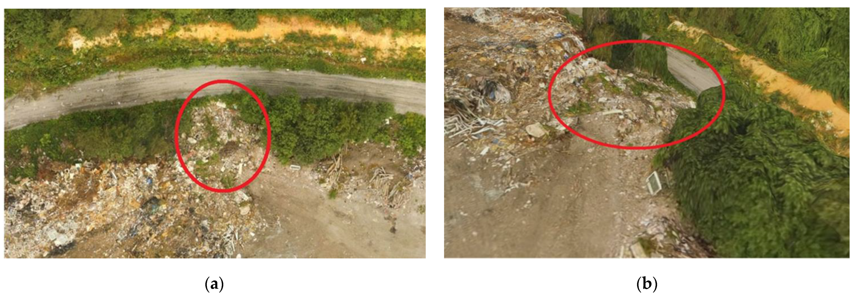
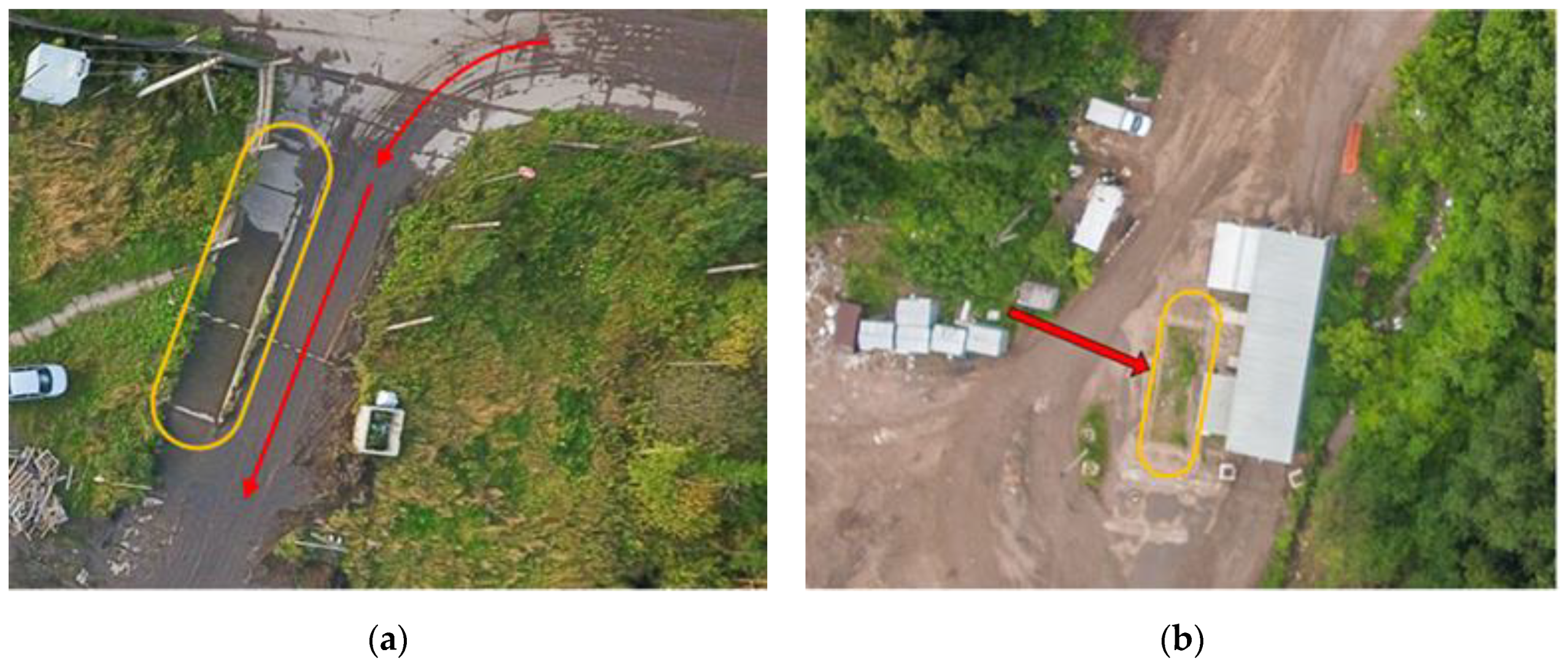
In a number of cases, indirect signs can also help to determine the state of the structures and whether they are performing their function. For example,
Figure 3 shows fragments of the aerial photographs of two MSW landfills in the Perm Region, Russia, with visible reservoirs for washing the wheels of garbage trucks.
However, in the left image of
Figure 3, the wheel tracks show that the garbage trucks are going along a different path (bypassing the reservoir), in the right image, the reservoir is overgrown with grass. Thus, it is established that wheel disinfection was not being performed at both sites at the time of the aerial imagery (despite the presence of the appropriate facilities).
Aerial imagery does not usually allow for a deeper verification of compliance with these requirements (for example, efficiency of checkpoints). Nevertheless, the increased detail of aerial photographs, compared to satellite images, makes it possible to interpret the images of a larger number of relevant infrastructure objects and, accordingly, to more fully assess the fulfilment of this group of technological requirements.
An important aspect of landfill operation is the operational system for landfill leachate and wastewater. According to the basic requirements for landfill operation, the landfill leachate coming out of the waste mass, as well as the wastewater from the site, must be collected and treated to the level required by the standards. To fulfil this, a network of drainage ditches and storm sewers are built on the territory of the landfill, which drains the wastewater into special containers or storage ponds. Local treatment facilities can be installed at the WDS, or the runoffs can be transported to third-party treatment facilities.
The condition of all engineering structures is subject to control and assessment. With the help of aerial imagery, one can check for the presence of blockages in ditches and canals and the integrity of their banks, monitor water levels in the canals and storage tanks, assess the degree of its contamination with waste, and identify drainage leakages.
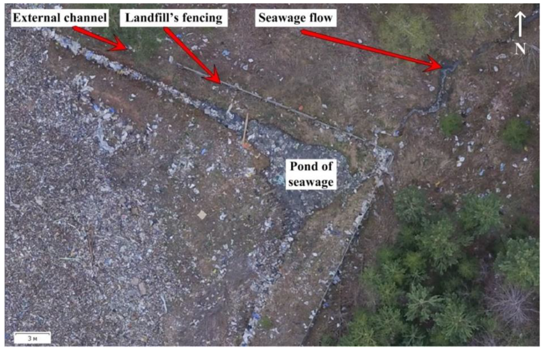
Figure 4 shows an example of wastewater leakage detection from the territory of the MSW landfill “N” in the Perm Region, Russia. The figure clearly shows the drainage canal along the perimeter of the waste heap. Surface runoff and landfill leachate are collected in a canal and enter a small storage pond located in the corner of the fenced-in area. The orthophotoplan shows that the pond is overflowing, and the runoff flows out of the landfill territory through a small hollow and goes into the adjacent forest. The water surface of the canal and pond is heavily polluted with waste; some of it, together with runoff, is carried downstream of the watercourse, thereby polluting the underlying lands. This leakage is indistinguishable in publicly available satellite images.
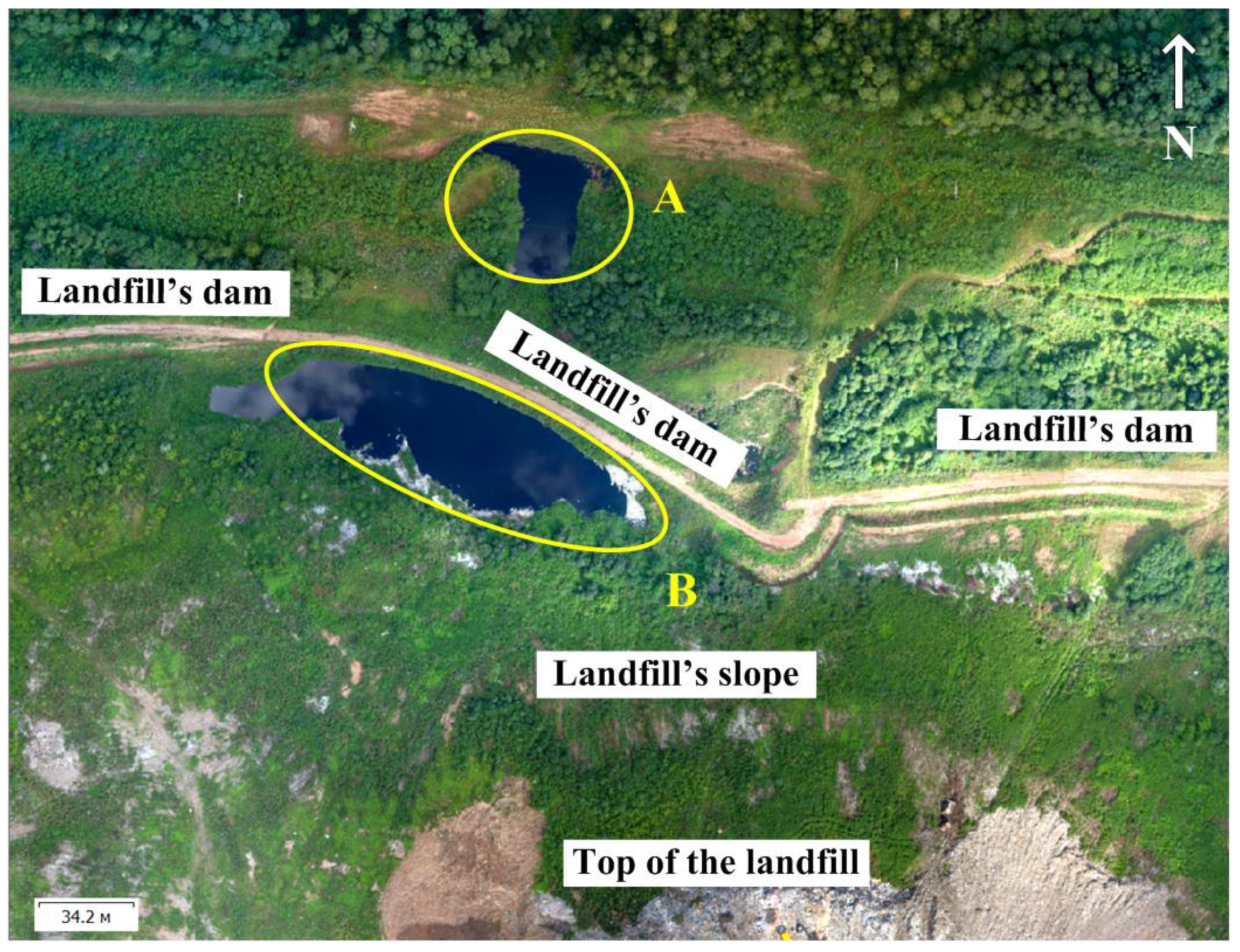
The integrity of dams is usually monitored directly (visually) but, sometimes, it is necessary to evaluate indirect signs. Thus, in
Figure 5, two similar leachate ponds are visible: one within the landfill (pond B), the other outside of it (pond A). This suggests that leachate is seeping through the dam, despite its apparent integrity.
In the US and EU legislation, there are also requirements for the arrangement of landfill gas handling systems at landfills. Landfill gas that is discharged from the waste mass must be collected through a system of wells and pipelines and fed into utilization or incineration plants. Unfortunately, at the studied Russian landfills, there are no landfill gas handling systems (which is indicated by the absence of the relevant mandatory legislative requirements); therefore, it was not possible to test the efficiency of the remote monitoring of such facilities in practice.
3.4. Ensuring Stability of the Waste Mass
Ensuring the stability of the waste mass and associated structures is the most important requirement for safe landfill operation. It consists of preventing landslides, collapses, cracking and destruction of the waste mass. In the EU Directive [
31], these requirements are spelled out explicitly. In the Russian legislation, specific standards are established in this regard, in the “instructions for the design, operation and reclamation of landfills for solid domestic waste” [
34].
A key measure to ensure the stability of the mass is the correct planning of its dimensions, with the slope angles not exceeding the standard values (in Russian legislation, this is an angle of 1:4 [
34]). In addition, the slopes must be reinforced with soil or other inert materials in a timely manner. The regular compaction of waste, which ensures the necessary connectivity of the mass, also plays an important role.
The steepness of the waste body slopes is traditionally estimated according to data from ground geodetic surveys, but they take time and are not always safe for personnel (for example, examining edges of steep slopes composed of unconsolidated waste). Space imagery offers limited opportunities for the assessment of the stability of the waste heap.
Aerial imagery compares favorably with these methods; it can be carried out quickly and with minimal costs, with no risk to personnel, and the aerial photographs obtained can be promptly processed in special, photogrammetric software, resulting in orthophotoplans, height maps and three-dimensional polygonal models of the facility. The photogrammetric software allows the building of profiles of the mass and the assessment of the compliance of its surface layout with design solutions; this is achieved by building a slope map and identifying areas where the standard slopes exceed this. Such analysis is faster and easier than that which is performed when processing ground geodetic survey data in the environment of computer-aided design systems. In a number of cases, it is even possible to detect signs of destruction processes in the mass, and areas of slope collapse, through visual interpretation.
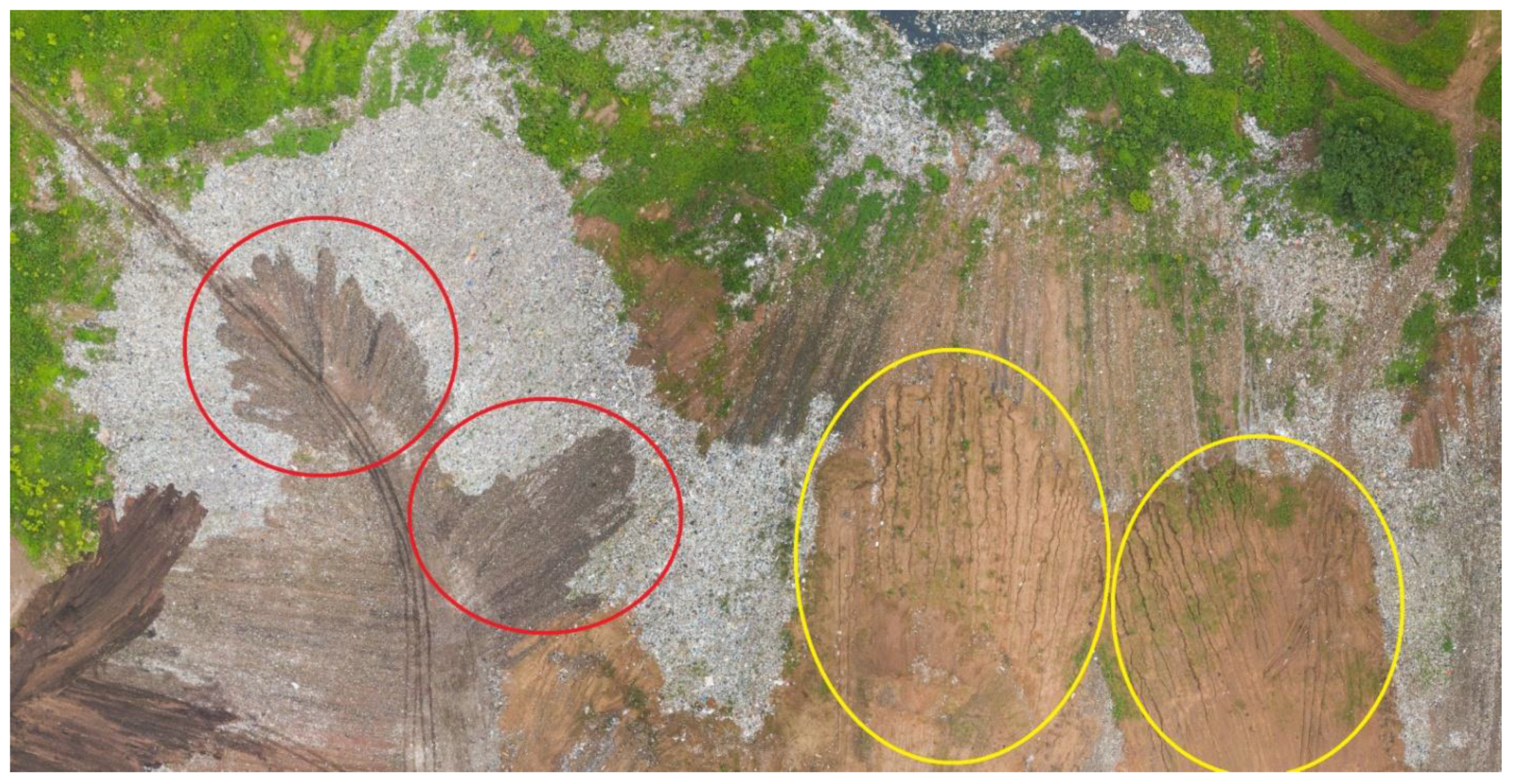
Figure 6 shows the result of the slope collapse at Landfill “Z”. It is clearly visible that, after the collapse of the mass, the waste filled the outer annular canal in this section of the slope and, together with the wastewater, spread down the relief.
In aerial photographs and orthophotoplans, areas with collapsed slopes are usually recognized as ‘tongues’ of waste extending beyond the border of the mass towards the adjacent territory. Even more reliably, collapses can be noted via a polygonal 3D model of a facility.
Figure 7 shows another example of a waste slope collapse.
3.5. Other Aspects of Landfill Operation
The list of legally approved standards for landfill operation is not limited to the above-mentioned groups of requirements. The four selected groups are the most universal requirements reflected in all of the analyzed documents, and the compliance with which (in most cases) can be monitored using visual analysis of unmanned aerial imagery data. There are other requirements for which aerial imagery is less effective, but, nevertheless, can also be used.
For example, in all of the regulatory documents reviewed, a group of requirements is established for the input control of waste that is brought to the landfill. For example, MSW landfills usually do not accept liquid waste, or associate it with strict restrictions [
31,
32,
33].
Despite the fact that routine operations of incoming control are mainly related to the procedures for the ground visual inspection of the imported waste and laboratory studies of waste samples, aerial imagery can help to reveal waste that was imported to the facility and is prohibited from disposal (for example, the disposing of wastewater sludge at landfills for solid waste).
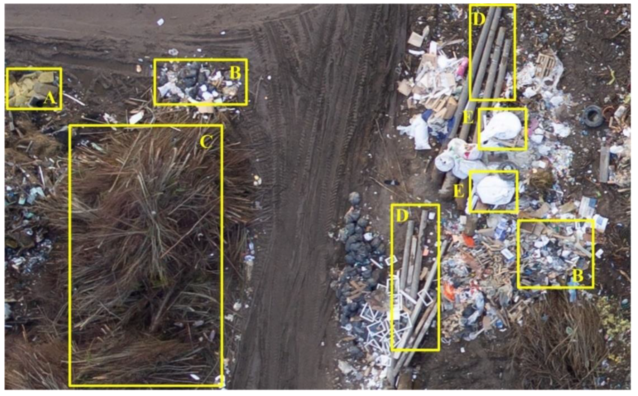
Figure 8 shows an example of determining the type of waste stored at dumpsite “B” in the Perm Region, Russia.
It has been shown that, even with a flight height of 172 m, a high-quality sensor (in this case, a full-frame Sony DSC-RX1R camera) makes it possible to confidently distinguish accumulations of construction waste from accumulations of MSW, as well as distinguish different subcategories of construction waste and MSW.
It was mentioned above that, in order to ensure stability of the waste mass, as well as to limit the impact of the landfill on the environment, waste disposal should be carried out according to individual disposal maps, in accordance with the landfill filling scheme. In the legal acts, such a requirement is usually not explicitly stated, however, at the level of sector regulations, similar norms can be found in European, American, and Russian legislation [
31,
32].
Remote sensing (both aerial imagery and space imagery) makes it possible to assess the degree of waste storage orderliness and compliance with the borders of disposal maps.
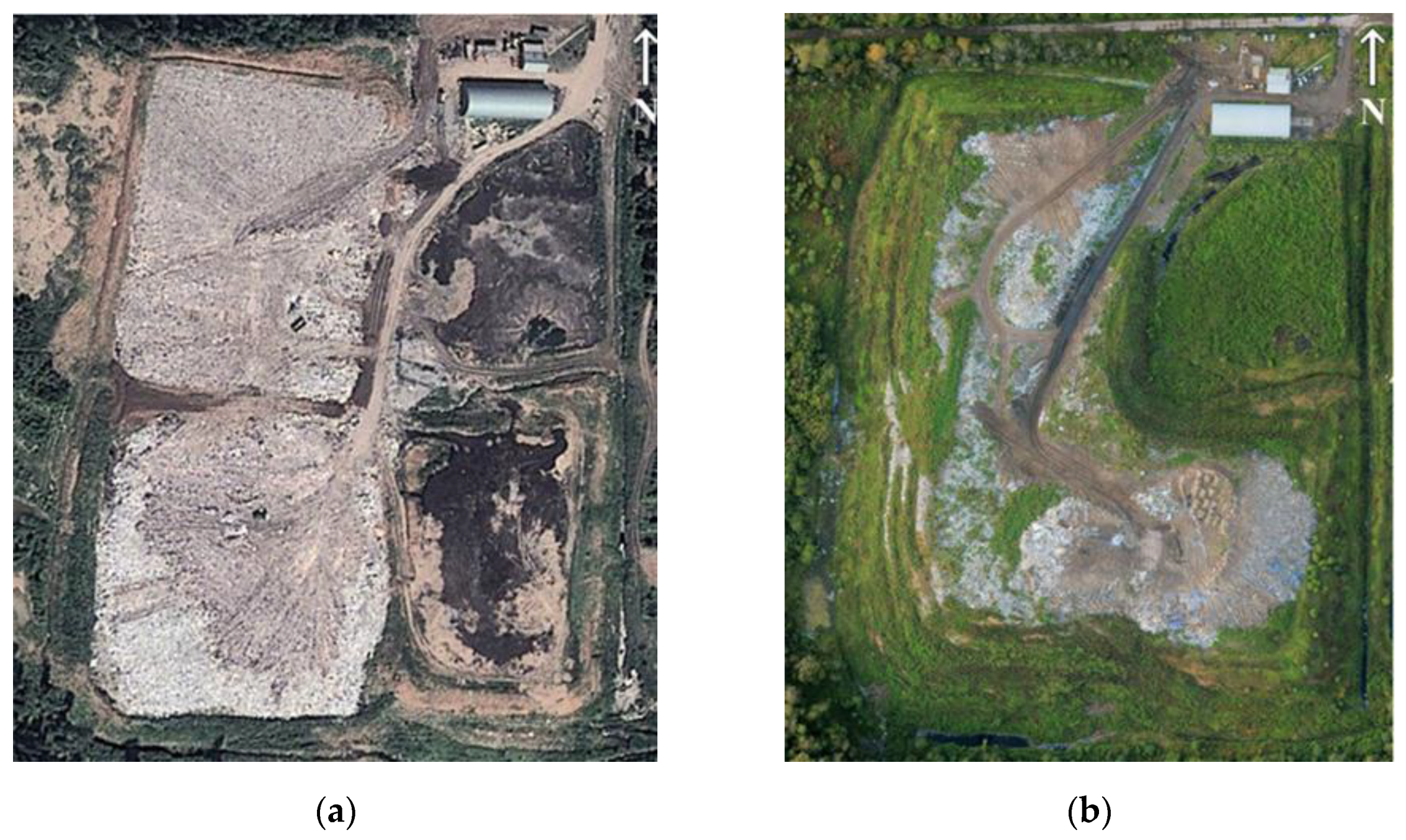
Figure 9a shows a satellite image of MSW landfill “Z” in Perm Region, Russia, taken in the summer of 2011.
Figure 9a shows, relatively clearly, four disposal cells separated by temporary passages. On the left, one below the other—two operated waste disposal cells and, on the right, also one under the other—two closed waste disposal cells.
Figure 9b shows an orthophotomap of the same landfill, based on the results of unmanned aerial imagery in 2019. One can see that waste is now placed on one of the old cells (in the southeast) and, most importantly, all three existing cells have merged into one large disposal site, the entire area of which (with the exception of the slopes) is covered with waste.
In a number of cases, other tools are required for spatial analysis of the photogrammetric processing results of aerial photographs, e.g., for constructing the actual surface of the waste mass and comparing it to the design surface or for calculating the volume of waste stored on separate disposal cells, etc. The solution to such problems of technological monitoring is the subject of separate studies.
4. Conclusions
In the course of this research, it was found that a significant portion of the compliance of landfills with the regulatory requirements that are mandatory for Russian, US and EU legislation can be monitored remotely—through aerial imagery from a UAV equipped with a standard RGB camera.
In particular, such monitoring works well for the technological processes of waste storage in disposal cells, waste compaction and intermediate isolation. It is impossible, of course, to control the correct handling of each batch of waste that is imported to the landfill, but aerial imagery is quite capable of establishing the absence or presence of gross systematic errors in the main technological processes at the landfill. The results of performing certain technological operations can be monitored both directly and by indirect (indicator) signs; the compilation of lists of such signs is a matter for future research.
In most cases, unmanned aerial imagery is quite effective for assessing the fulfillment of the so-called construction and planning requirements for landfills associated with the presence of certain structures and engineering systems. Exceptions are cases with technical structures that are located in hidden areas, for example, underground (gas pipelines, closed drains, etc.). At the same time, it is not always possible to determine the actual performance and/or efficiency of openly located structures through aerial imagery; accordingly, it is possible that ground clarifying inspections could be required.
Unmanned aerial imagery provides great opportunities in terms of assessing the environmental impact of WDSs—in particular, it allows the detection of the scale and boundaries of such processes as the littering of the adjacent territory, its pollution by leachate and waste waters, etc. The evidence of these processes is often masked by vegetation or snow cover, so it is especially important to maintain the seasonality of aerial imagery (to perform surveys in a leafless and snowless period).
Unmanned aerial imagery allows for the monitoring of the most important structure on the territory of the landfill—the landfill body. By means of a simple visual analysis, it is possible to determine the configuration of the landfill body, assess the steepness (and hence the stability) of the slopes, check the insulating coating presence, and identify the possibilities of fire and signs of violation of the mass integrity (cracks, subsidence, etc.). It is advisable to supplement the visual analysis of the orthophotoplan and 3D model with a complex of measurements in the photogrammetric data processing software in order to calculate the exact quantitative parameters of the waste mass.
Despite the fact that the size of the complete list of standards for the operation of landfills depends on national legislation, according to the results of the presented study, it can be argued that the use of a UAV with a standard camera allows researchers to monitor the compliance with most of the basic requirements for landfill operation.
The main advantages of using UAVs within the framework of the proposed methodology are associated with the promptness of obtaining information on the situation at the facility and the high level of detail of this information, which favorably distinguishes unmanned aerial imagery from satellite imagery, as well as the ability to conduct observations and measurements that are difficult to implement in the practice of ground inspection of facilities (inspection of hard-to-reach or dangerous-to-visit areas).
The optimal software for the accumulation, analysis and comparison of different time aerial imagery data is the GIS software, or the software of specialized monitoring platforms, which were already mentioned in
Section 1 (DroneDeploy, Propeller Aero). This software makes it possible to combine the results of aerial images at different times and, accordingly, greatly facilitates the process of their comparative analysis. Other researchers also mentioned the fact that the use of GIS complements the methods of air monitoring very well—in relation to the post-operational stage of the life cycle of landfills [
35]. The procedures for the processing and analysis of aerial imagery data in GIS also require further development.
Due to the relatively small size of research objects (landfills and dumps usually occupy an area from several hectares to several tens of hectares), the relatively low battery charge of a small drone is not a limiting factor for the performance of aerial inspections. The disadvantages of the technology include its meteorological dependence (the impossibility of survey during periods of precipitation or during strong winds). However, it still has an advantage over space photography in terms of the degree of such a dependence.
A factor that limits the use of this technology to some extent is the need to use specialized software for photogrammetric data processing, which entails additional financial costs. The solution here may be to use open-source software, but the authors are unaware of the experience of using such software.
Nevertheless, the mentioned costs seem to be justified, since the results of landfill surveys using UAVs provide rich material for making timely management decisions and can be used by both landfill operators and other interested parties (for example, regulatory authorities).


