Article

On the Aerodynamic Analysis and Conceptual Design of Bioinspired Multi-Flapping-Wing Drones

by
Ethan Billingsley
1,
Mehdi Ghommem
2,
Rui Vasconcellos
3 and
Abdessattar Abdelkefi
1,*
1
Department of Mechanical and Aerospace Engineering, New Mexico State University, Las Cruces, NM 88003, USA
2
Department of Mechanical Engineering, American University of Sharjah, Sharjah 26666, United Arab Emirates
3
Campus of São João da Boa Vista, São Paulo State University (UNESP), São Paulo 01049-010, Brazil
*
Author to whom correspondence should be addressed.
Drones 2021, 5(3), 64; https://doi.org/10.3390/drones5030064
Submission received: 7 June 2021 / Revised: 10 July 2021 / Accepted: 14 July 2021 / Published: 18 July 2021
(This article belongs to the Special Issue Bio-Inspired Drones)

Abstract

:
Many research studies have investigated the characteristics of bird flights as a source of bioinspiration for the design of flapping-wing micro air vehicles. However, to the best of the authors’ knowledge, no drone design targeted the exploitation of the aerodynamic benefits associated with avian group formation flight. Therefore, in this work, a conceptual design of a novel multi-flapping-wing drone that incorporates multiple pairs of wings arranged in a V-shape is proposed in order to simultaneously increase the propulsive efficiency and achieve superior performance. First, a mission plan is established, and a weight estimation is conducted for both 3-member and 5-member configurations of the proposed air vehicle. Several wing shapes and airfoils are considered, and aerodynamic simulations are conducted, to determine the optimal planform, airfoil, formation angle, and angle of attack. The simulation results reveal that the proposed bioinspired design can achieve a propulsive efficiency of 73.8%. A stability analysis and tail sizing procedure are performed for both 3-member and 5-member configurations. In addition, multiple flapping mechanisms are inspected for implementation in the proposed designs. Finally, the completed prototypes’ models of the proposed multi-flapping-wing air vehicles are presented, and their features are discussed. The aim of this research is to provide a framework for the conceptual design of bioinspired multi-flapping-wing drones and to demonstrate the sizing, weight estimation, and design procedures for this new type of air vehicles. This work establishes the first multi-flapping-wing drone design which exploits the aerodynamic features of the V-formation flight observed in birds to achieve superior performance in terms of payload and endurance.

1. Introduction

Many research efforts have focused on birds as the source of bioinspiration for the design of flapping-wing air vehicles [1,2,3,4,5]. For example, Hassanalian et al. [1,2] presented the sizing process and weight estimation of a bioinspired flapping-wing micro air vehicle (FWMAV) named Thunder I. This FWMAV used a mockingbird-inspired planform with a wingspan of 0.7 m. Furthermore, flight tests demonstrated an endurance of 11–13 min using moderate throttle input and excluding any extra payload.
The use of flapping wings in a single drone design has been investigated [6,7,8,9,10,11]. The dragonfly is a notable source of bioinspiration for flapping-wing air vehicles incorporating multiple wings. A well-established air vehicle of this design is Festo’s BionicOpter, a commercially developed, dragonfly-inspired flapping-wing air vehicle capable of hovering, multidirectional flight, and gliding [6]. In addition, Lane et al. [7] investigated dragonfly-inspired flapping mechanisms which used four wings based on the bumblebee planform. Two flapping mechanisms were investigated and one of the mechanisms was selected to measure the aerodynamic forces produced on a thrust stand. Of interest, there also exists a flapping-wing air vehicle named the NUS-Roboticbird which is inspired by insect flight [8]. This design incorporated two pairs of flapping wings and does not require the use of a tail. Instead, stroke plane modulation along with frequency variation were used in order to control roll, pitch, and yaw. The fabricated design demonstrated the ability to hover and exhibited multidirectional flight capabilities.
From the aforementioned examples, flapping-wing air vehicle designs incorporating more than one pair of wings commonly use insects as the primary source of bioinspiration. Interestingly, the formation flight of birds may provide a unique source of bioinspiration for the design of novel efficient drones including multiple pairs of flapping wings. To elaborate, there exist some species of birds which have been observed to fly together in a V-shape arrangement called “V-formation” [12,13,14,15,16]. Throughout the literature, studies have demonstrated that this arrangement helps the group of birds to save energy and increase endurance. First, Lissaman and Schollenberger [12] theorized that 25 birds flying in formation could achieve an increase in range of up to approximately 70% compared to a bird flying alone. Furthermore, a study on pelicans trained to fly in V-formation found that both heart rate and wingbeat frequency decreased compared to a bird in solo flight [17]. From a computational perspective, Ghommem et al. [18] used an aerodynamic solver based on the unsteady vortex lattice method (UVLM) to analyze the aerodynamic performance of multiple pairs of flapping wings arranged in a V-formation. Using the optimal spacing parameters for an arrangement of seven members, simulation results revealed a significant increase in the lift and thrust coefficients and a decrease in the power coefficient for every member in the group in comparison with the solo configuration. More recently, a numerical study was conducted using a Navier–Stokes-based immersed boundary method solver to simulate multiple FWMAVs in V-formation flight. In this study, both a 3-member and 5-member configuration were considered, and the impact of several key parameters on the aerodynamic performance was investigated. These include the lateral, longitudinal, and vertical separation distances in addition to the phase difference between the flapping motion of each member. The numerical results showed that, compared to a solo flight, the thrust and lift could be increased by 25% and 14%, respectively, when flying in V-formation. On the other hand, a reduction of 19% in both lift and thrust was possible, depending on the separation distance between members and phase difference [19].
Based on these observations, it is evident that multiple flapping wings in V-formation flight can result in significant performance benefits for the group compared to a single flapping wing. Several research studies investigated the feasibility of swarms or groups of drones flying in formation [20,21,22,23]. However, the arrangement of multiple pairs of flapping wings in a single vehicle based on the formation flight of birds has not been reported up to this point. In this work, a novel drone design that exploits the aerodynamic benefits of formation flights to achieve superior performance in terms of lift generation and endurance is proposed. Therefore, the goal of this work is to develop a conceptual design for a multi-flapping-wing drone (MFWD) that incorporates multiple pairs of wings in V-formation in order to increase the propulsive efficiency with an effective design of the formation angle, angle of attack, wing shape, and airfoil. This work is the first to propose a multi-flapping-wing drone design which is made of multiple flapping wings fixed in a V-shaped arrangement in order to exploit the aerodynamic features of birds in formation flight. To do so, first, a mission plan is established, and a weight estimation is carried out for both 3-member and 5-member configurations of this type of air vehicle. Next, different wing shapes and airfoils are considered and aerodynamic simulations using UVLM are conducted to identify the optimal planform, airfoil, formation angle, and angle of attack for the selected mission. UVLM is a well-established method that has been extensively used for the aerodynamic analysis of flapping wings [18,24,25,26,27]. UVLM requires much less computational resources and simulation time in comparison to high-fidelity CFD tools, which makes the present method suitable to perform a rapid and reasonably accurate exploration of a large design space. Following a sizing method, horizontal and vertical tails are selected to secure the static stability of the air vehicle. Several flapping mechanisms are discussed and considered for implementation in the design. Finally, the completed prototypes’ models of both the 3-member and 5-member designed vehicles are presented and their features are discussed. The contribution of the present work is a comprehensive study on the design process of a novel multi-flapping-wing drone. The design study includes sizing and weight estimation processes along with an unsteady aerodynamic analysis, stability analysis, and overview of the actuation mechanism and the development of a full CAD model. The simulation results obtained from the present methodology demonstrate significant increases in the propulsive efficiencies of up to 71% and 74% corresponding to the 3-member and 5-member drone designs, respectively.

2. Mission Plan Description

The novel MFWD discussed in this work has several potential applications. First, the drone may be deployed to survey an area in search of a target. Such is the case in reconnaissance applications, where surveillance of sensitive areas must be conducted with low risk of detection. Due to the flapping motion of the wings along with the naturally occurring V-formation, this drone is well-suited for blending in with the environment. Additionally, custom paint and feather-like patterns may be added to the design to further convey the appearance of a flock of birds when viewed from a distance. Alternatively, an enhanced endurance of this drone is expected to improve search and rescue applications, where longer flight times may be required to identify a lost individual. Given these applications, a mission plan is established to demonstrate how this drone may be used to identify a target and record its location. This mission plan is shown in Figure 1 and is conducted as follows. First, the drone is hand-launched to allow the wings to begin flapping and avoid intersection with the ground. Next, the drone will ascend to the desired altitude before searching for the target. Depending on the application, this cruising altitude may be higher for increased stealth or lower for better visibility of the ground. In order to maintain this altitude, the flapping wings are oriented at a fixed angle of attack such that the total lift is equal to the weight. In addition, the position of the elevons in the tail may be adjusted during flight to trim the angle of attack as needed to maintain a constant cruising altitude. After reaching the desired altitude, the drone will fly at a cruising speed of 8.5 m/s with a flapping frequency of 3 Hz. This cruising speed is proven to be achievable by Thunder I [1], and the selected flapping frequency is similar to that noted in observations of the black-browed albatross [28]. The next step is to initiate a sweeping procedure to thoroughly inspect the area for the target. By performing the sweep, the drone will attempt to locate the target and record its coordinates using an onboard computer and GPS module. After recording the location, the drone will return and start the descent back to its original location. In order to descend, the drone may reduce its flapping frequency and transition to a glide during the final approach. For the glide transition, the wings will lock at a flapping amplitude of 0 degrees (horizontal) to avoid intersection of the wings and crankshaft with the ground. In addition, wheels are mounted underneath the MFWD in order to prevent damage when landing on a hard surface.

3. Sizing and Weight Estimation

Throughout the course of this work, Thunder I serves as the reference design and inspiration, given its successful flight demonstration [1,2]. In addition, the cruising velocity and wingspan are similar to the values proposed for the MFWD. However, the aspect ratio selected for the MFWD is set to 10.56, which is constrained by one of the considered planforms, as will be discussed in the subsequent section. This aspect ratio is larger than that used for Thunder I, and results in a smaller wing surface area of 0.0684 m2 compared to the 0.127 m2 surface area of Thunder I. This difference is considered in Equation (1) when estimating the structural weights. It is important to note that throughout this analysis, the term “weight” refers to the calculated value in grams (g) rather than Newtons (N). The weight estimation is conducted as follows. First, the preliminary estimation is calculated using Equation (1).
W P M F W D = N ( W E T I + ( S M F W D / S T I ) W S T I )
Here, W P M F W D represents the preliminary weight estimation of the MFWD. Furthermore, W E T I and W S T I represent the electrical and structural weights of Thunder I and are set equal to 135 g and 215 g, respectively [1]. S M F W D and S T I denote the surface areas of the MFWD and Thunder I, respectively, while N denotes the number of members used in the MFWD configuration. In general, the electrical and structural weights for a flapping-wing drone are given by [2]:
W e l e c t r i c a l = W b a t t e r y + W p a y l o a d + W a v i o n i c s + W p o w e r p l a n t
With the exception of the battery, the weights of each of these electrical categories are further divided as follows:
W p a y l o a d = W l o a d s + W s e n s o r s + W c a m e r a s + W o t h e r
W a v i o n i c s = W s e r v o s + W a c t u a t i o n   m o t o r s + W r e c e i v e r s + W n a v i g a t i o n   s y s t e m
W p o w e r p l a n t = W d r i v e   m o t o r s + W s p e e d   c o n t r o l l e r s
Furthermore, the structural weights are subdivided as shown in Equation (6):
W s t r u c t u r a l = W w i n g + W t a i l + W f u s e l a g e + W m e c h a n i s m + W o t h e r
Then, the weight of the wing is given by:
W w i n g = W w i n g   s t r u c t u r e + W w i n g   m e m b r a n e + W c o n n e c t i o n s
where
W w i n g   s t r u c t u r e = W l e a d i n g   e d g e   s p a r s + W d i a g o n a l   s p a r s + W r i b s
The remaining structural weights are then broken down further using the following equations:
W t a i l = W t a i l   s t r u c t u r e + W t a i l   m e m b r a n e + W c o n n e c t i o n s
W f u s e l a g e = W f u s e l a g e   s t r u c t u r e + W c a p e + W c o n n e c t i o n s
W m e c h a n i s m = W g e a r b o x + W l i n k i n g   b a r s + W c r a n k s h a f t + W j o i n t s + W e x t e r n a l   p a r t s
Furthermore, Hassanalian and Abdelkefi [2] listed percentages of the total weight corresponding to the powerplant, payload, battery, avionics, and structural components for three different categories based on common MAV weight ranges. For the weight range applicable to Thunder I, these percentages are set to 16%, 1%, 14%, 9%, and 60%, respectively. These percentages are then applied to the preliminary weight estimation for each category. However, for the “Structural” category, extra weight is considered to account for the additional structural components needed to separate the members. This extra weight increases the preliminary weight estimation by 10%, and this increased value is now referred to as the baseline weight estimation. This value is listed for both the 3-member and 5-member MFWD configurations as the first “Total” in Table 1 and Table 2. Next, two additional estimations are considered for applications requiring increased endurance, requiring the use of a larger battery. To this end, sufficient weight is added to the “Battery” category in order to increase the baseline weight estimation by both 10% and 25%. The final calculated values for each category and each weight estimation are presented in Table 1 and Table 2 for both configurations.

4. Aerodynamic Analysis: Role of Bioinspiration and Effective Design of the Formation Angle and Angle of Attack

Following the weight estimation procedure, aerodynamic simulations are conducted using a Fortran-based implementation of the unsteady vortex lattice method (UVLM). This UVLM-based aerodynamic solver is used primarily given its capability to capture unsteady effects associated with flapping motion [18]. This method is relatively fast in comparison with Navier–Stokes-based solvers, which require much more computational resources [29]. In this method, the wing surface is first discretized into the desired number of spanwise and chordwise panels, and vortex rings are offset by one-fourth of each panel’s local chord length. Collocation points are placed at the center of each vortex ring, and these rings induce a velocity on the points according to the Biot–Savart law. After the first time step, the vortex rings at the trailing edge of the wing are shed to constitute the first row of the wake vortex rings, which maintain a constant strength and move with the local velocity. Imposing the no-penetration condition, the velocities induced on each collocation point by the bound (lifting surface) and wake vortex rings are set equal to the normal velocity at each point resulting from the flapping motion of the wings. Through this relationship, the vortex strengths at each time step are computed, which enables the calculation of the aerodynamic loads. As for the present analysis, the number of panels and time steps used in this method are selected to secure convergent solutions. For more information on the unsteady vortex lattice method, the reader is referred to [30]. It should be noted that the implementation of the present aerodynamic solver has been verified by comparing the simulation results of flapping wings arranged in a V-shape against previously-published numerical results [18].
Three wing shapes are considered for the following analysis, namely, the albatross, elliptical, and rectangular planforms, as shown in Figure 2. To specify these wing shapes, equations for the leading and trailing edges are determined analytically for both the elliptical and rectangular wing shapes. Then, the Image Processing Toolbox in MatLab [31] is used to isolate the profile of the albatross wing shape from a top-down view, allowing polynomials to be fit to both the leading and trailing edges. In addition, the cambered Selig 1223 and the symmetric NACA 0012 airfoils are selected to investigate the effects of camber on lift production (see Figure 3). Of interest, UVLM only requires the camber line to be specified for creating the wing mesh. Therefore, the camber line of the NACA 0012 airfoil is simply described using a straight line, while the camber line of the Selig 1223 is specified using a polynomial fit. The simulation parameters used in the present work are presented in Table 3.
For the first set of simulations, the NACA 0012 camber line is selected and applied to each wing shape. It should be mentioned that UVLM is only applicable for relatively small angles of attack [24]. Therefore, the highest simulated angle of attack is selected as 7 degrees, and is applied first for the NACA 0012 camber line to determine if enough lift is produced to counterbalance the total weight. Furthermore, formation angles between 116 and 173 degrees are tested to determine their influence on the total lift produced by the MFWD. For reference, a top-down schematic of five members arranged in V-formation is shown in Figure 4.

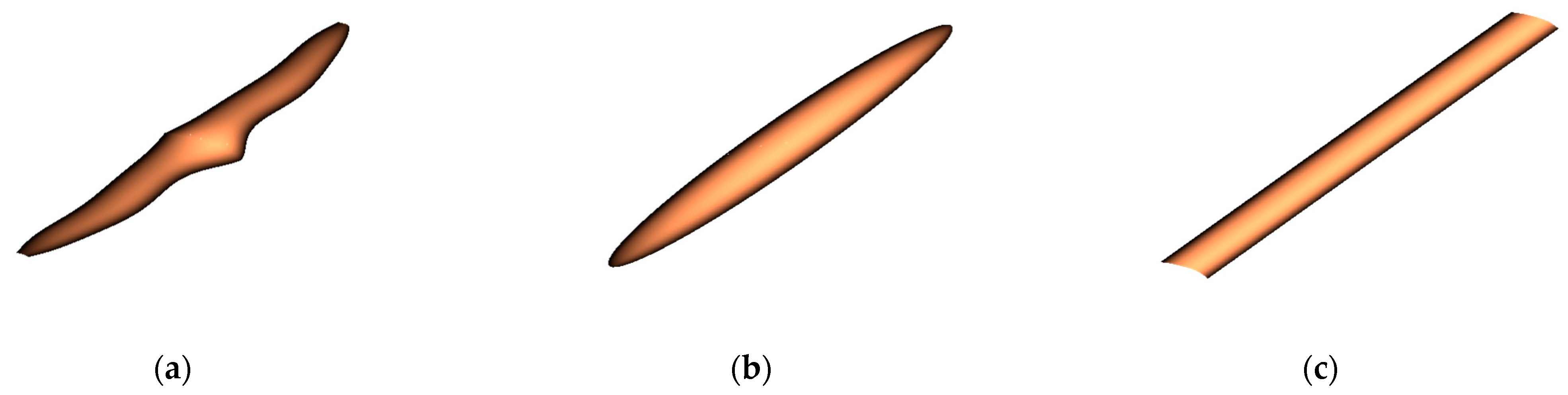
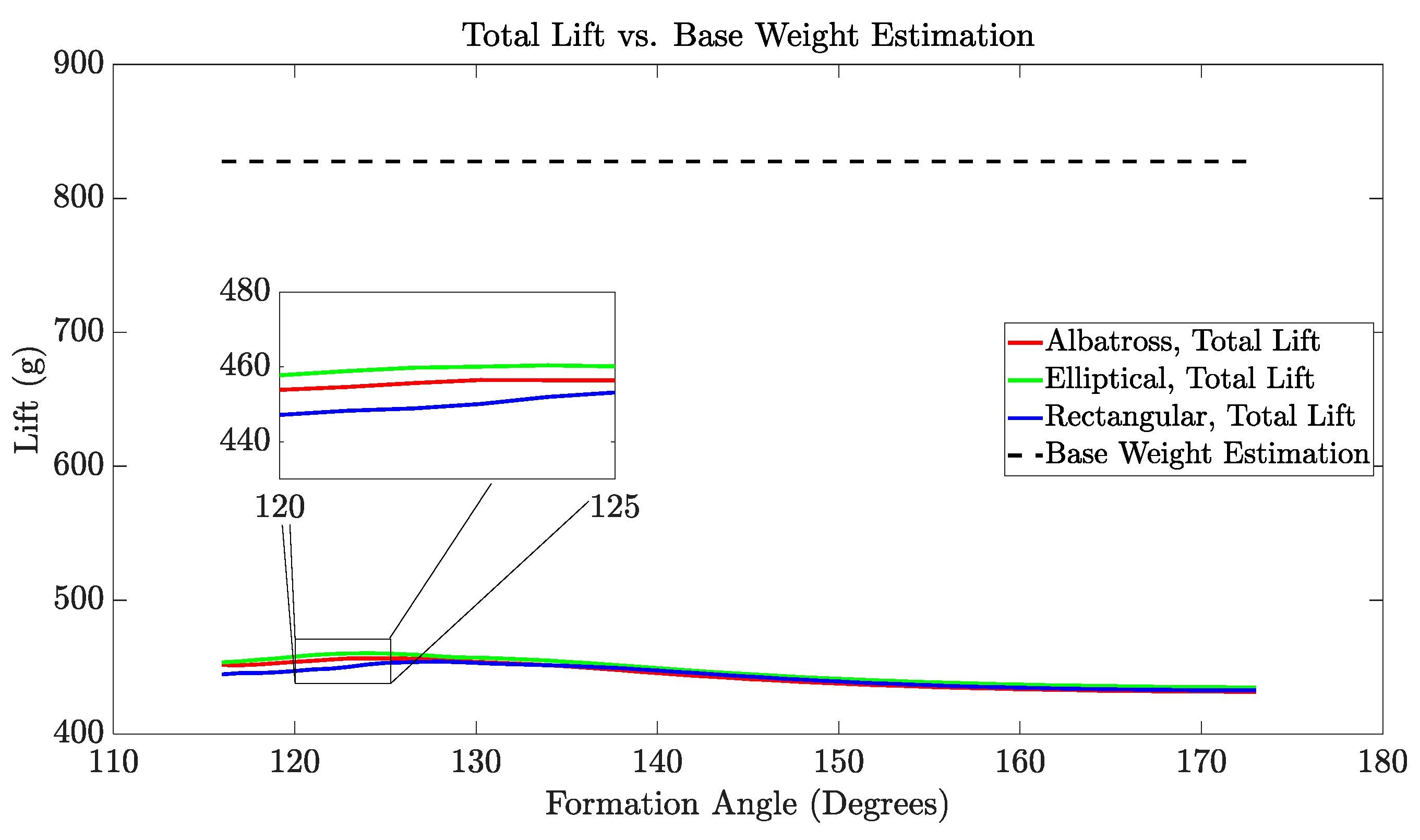
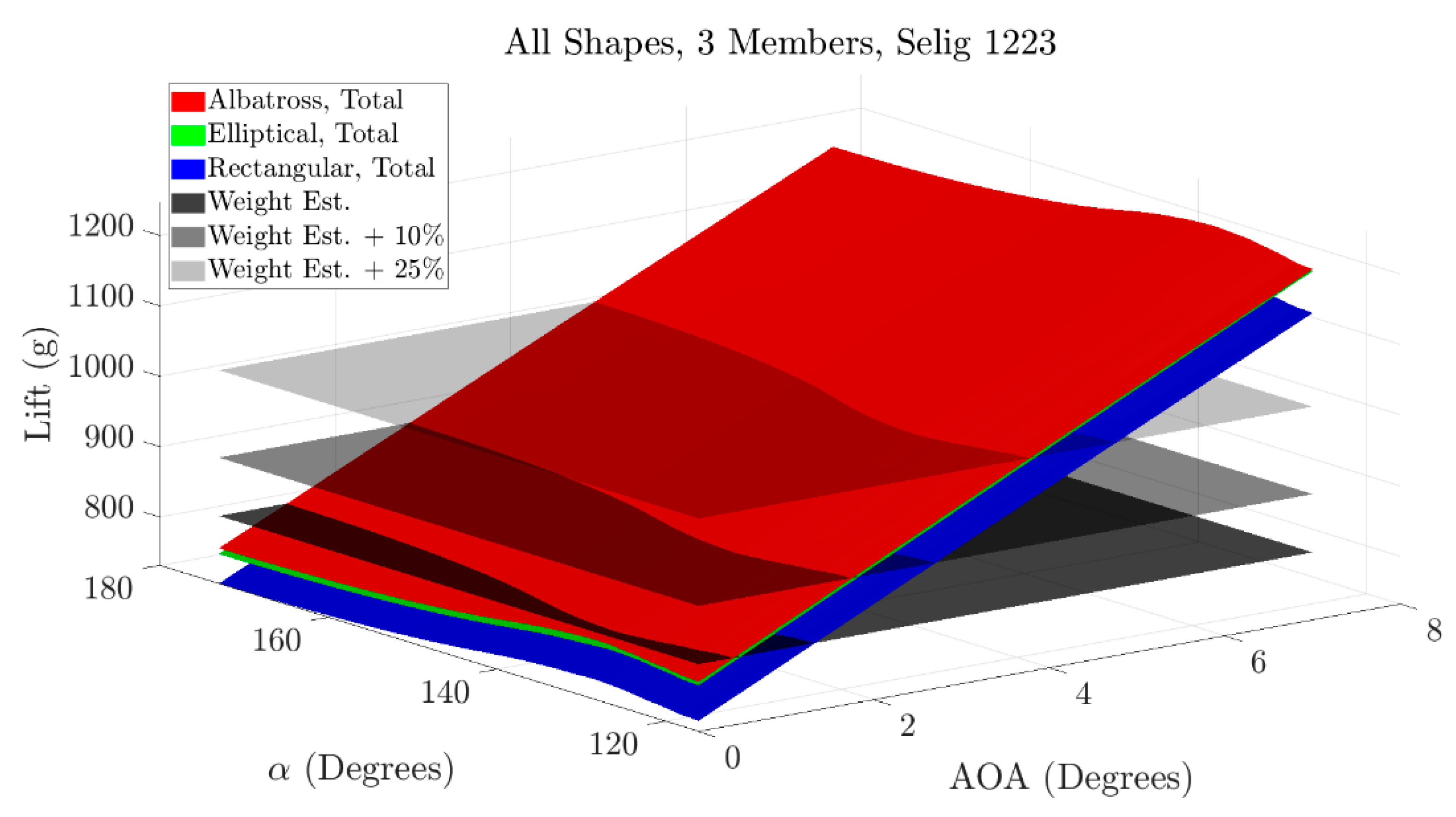
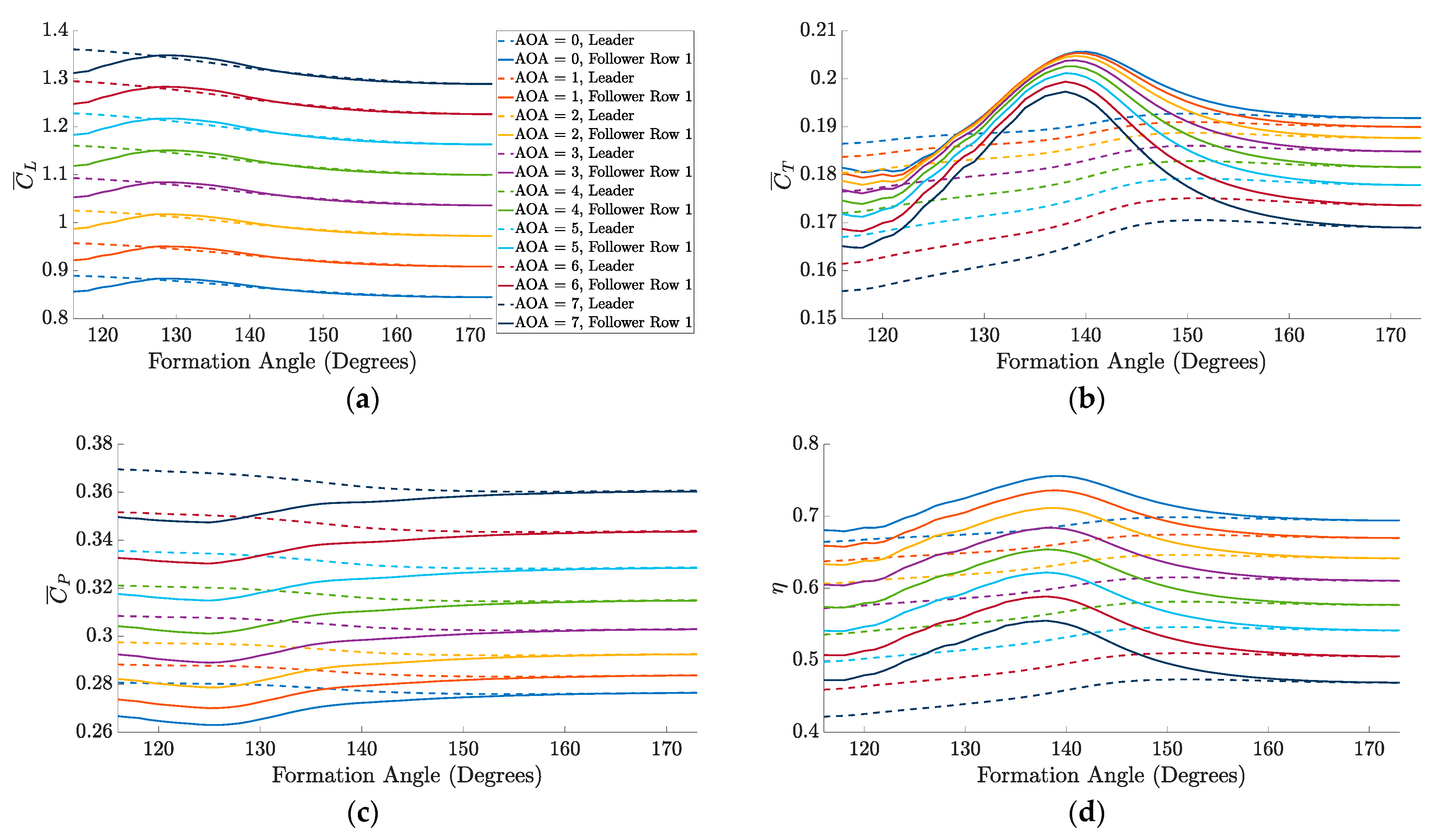
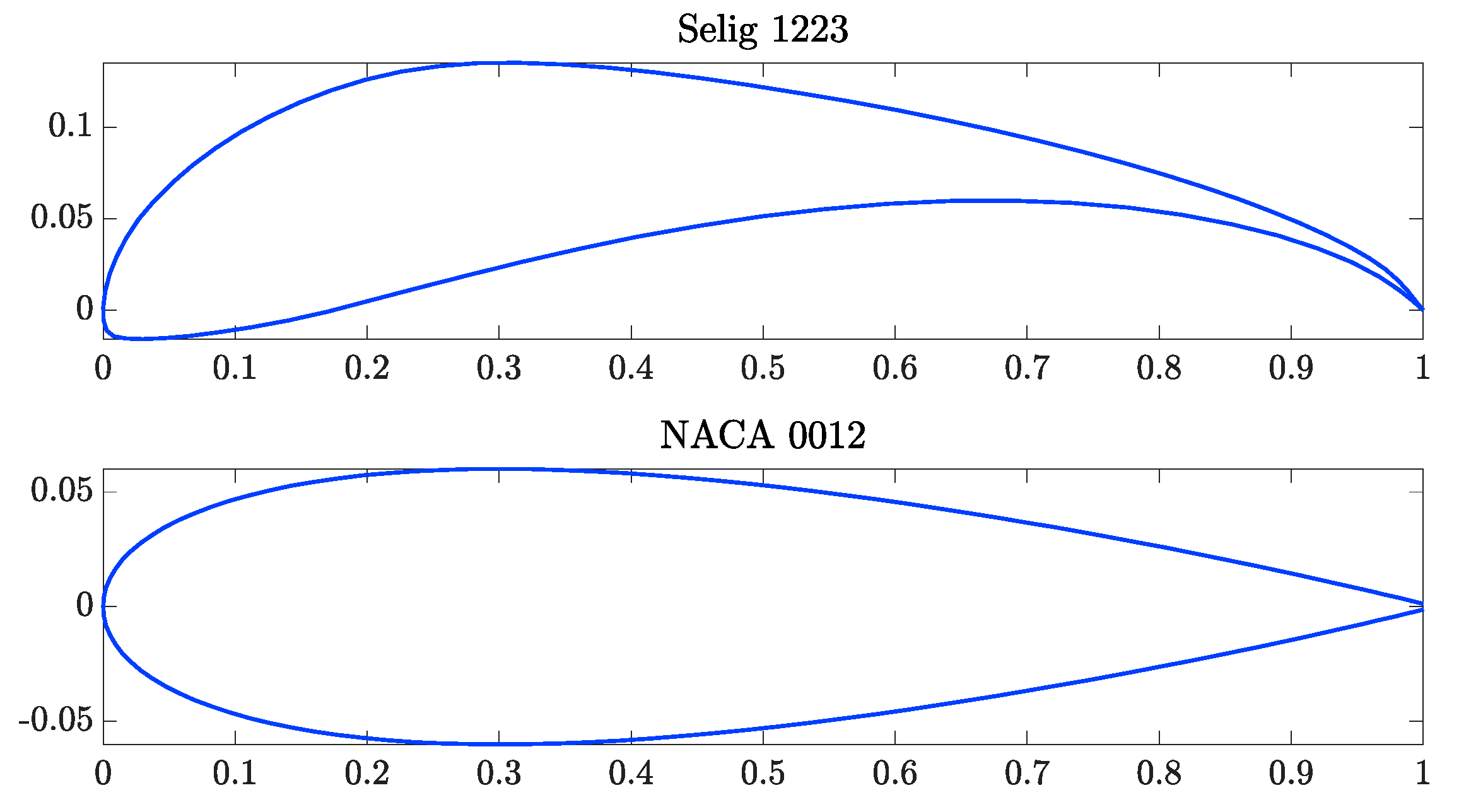
4.1. Multi-Flapping-Wing Drone’s Design for 3-Member Configuration

For the NACA 0012 airfoil, a 3-member V-formation is first considered. Figure 5 shows the variations of the total lift with the formation angle α . The aerodynamic simulation results reveal that none of the wing shapes produces enough total lift from the three members to meet or exceed the baseline weight estimation. Therefore, because 7 degrees is deemed the highest acceptable value for the angle of attack, the NACA 0012 airfoil profile is found to produce insufficient lift for this application. However, there are a few interesting things to note about these results. For one, it is evident that as the formation angle increases, the peak in the total lift for each wing shape occurs between 120 and 130 degrees. In addition, for this airfoil profile and set of input parameters, the elliptical wing shape results in the highest combined lift across the range of tested formation angles in comparison with the other two wing shapes. In summary, the key observation from these results is that the NACA 0012 airfoil is found to be inadequate, and then the Selig 1223 airfoil is used for all remaining simulations. It should be noted that for all aerodynamic simulations, the results generated over the range of formation angles are smoothened using a moving mean with a 5-degree sliding window.
The subsequent set of simulations uses the Selig 1223 airfoil to satisfy the lift requirements. Furthermore, the angle attack is varied between 0 and 7 degrees along with the formation angle as per the previous range to identify the suitable configuration that produced the required lift for each of the three weight estimations. In Figure 6, the total lift generated for each one of the wing shapes is represented as a surface with a unique color. Additionally, each of the three weight estimations are represented as a dark plane, with increasing transparency as the weight increases. As observed when using a symmetric airfoil, the total lift reaches a peak when the formation angle is between 120 and 130 degrees for all angles of attack. It should also be noted that the albatross and elliptical wing shapes produce similar levels of the total lift, although the albatross wing shape results in slightly higher values. In addition, both of these wing shapes outperform the rectangular wing shape in terms of total lift. Each surface corresponding to its wing shape intersects with the weight estimation planes at unique combinations of the angle of attack and formation angle. In other words, varying the formation angle results in a different corresponding angle of attack at the intersection point for each wing shape and each weight estimation.
There are two methods for selecting the most effective formation angle. First, the formation angle may be selected as the point at which the mean coefficient of lift produced by the follower row is maximized. It should be noted that the term “mean coefficient” refers to the averaged coefficient over a single flapping cycle, and applies to the lift, thrust, and power results shown in Figure 7a–c, respectively. As an example, Figure 7a is used to select this peak formation angle for the albatross wing shape. Alternatively, Figure 7d may be utilized to select the formation angle corresponding to the peak propulsive efficiency achieved by the follower row. Here, the propulsive efficiency refers to ratio of the power used to propel the wing in the forward direction over the aerodynamic power [25]. After selecting the formation angle, the corresponding angle of attack is obtained from the intersection of the weight estimation plane and the total lift plane. Following this methodology, the corresponding formation angle and angle of attack are listed in Table 4, Table 5 and Table 6 when maximizing either the mean coefficient of lift or peak propulsive efficiency of the follower row for each of the different wing shapes.
Table 4, Table 5 and Table 6 provide several insights regarding the performance of the different wing shapes. In Table 4, corresponding to the albatross wing shape, it is evident that when the mean coefficient of lift for the follower row is maximized, higher angles of attack are needed as the weight estimation increases. Additionally, the formation angle for maximizing the follower’s lift remains generally the same across each of the three weight estimations. When the propulsive efficiency of the follower row is maximized, the formation angle also remains relatively unchanged, but the angle of attack still demonstrates an increasing trend as the weight estimation is increased. With these combinations of parameters, new aerodynamic simulations are conducted to determine the corresponding propulsive efficiencies. These simulations demonstrate that, with increasing the weight and angle of attack, the global propulsive efficiency tends to decrease. Here, the term “global” refers to the average of the leader and follower row propulsive efficiencies. Indeed, since an increase in the angle of attack tends to create more induced drag, this would lead to a decrease in efficiency. This decreasing trend in propulsive efficiency is true for both the lift-prioritized simulations and the efficiency-prioritized simulations. However, the propulsive efficiency values for each of the predicted weights in the efficiency-prioritized simulations are higher than those obtained in the lift-prioritized simulations. Therefore, it is decided that the efficiency should be prioritized rather than the lift because higher propulsive efficiencies can be achieved for each of the estimated weights while still producing the required lift. All of the mentioned trends noted in the albatross wing shape are also observed for the other two wing shapes. However, the albatross wing shape results in highest propulsive efficiencies for each weight estimation in both the lift-prioritized and efficiency-prioritized simulations compared to the corresponding efficiencies for both of the other wing shapes. Therefore, the albatross wing shape is deemed the most effective option for the design of the 3-member MFWD.
Figure 8 illustrates the propulsive efficiency of the leader and follower row for all wing shapes when the baseline +10% weight estimation is considered, and the combination of the formation angle and angle of attack is based on the prioritized propulsive efficiency of the follower row. For all wing shapes, these values for the leader and follower row propulsive efficiency are averaged together to denote the global propulsive efficiency reported in the last row of Table 4, Table 5 and Table 6. It follows from Figure 8 that the albatross-inspired wing shape is performing better for the global efficiency, as shown in Table 4, Table 5 and Table 6, and for the leader and follower row individual efficiencies compared to the elliptical and rectangular counterparts.

4.2. Multi-Flapping-Wing Drone’s Design for 5-Member Configuration

Next, the same analysis is conducted while considering the 5-member configuration using each wing shape. Conveniently, the range of the formation angle and angle of attack may be narrowed down based on the results of the 3-member configuration shown in Table 4, Table 5 and Table 6 to speed up the computational aerodynamic simulations. Therefore, the range for the formation angle is reduced to 120–150 degrees, while the range for the angle of attack is reduced to 0–4 degrees. The three weight estimation planes along with the surfaces representing the total combined lift for each wing shape are shown in Figure 9. As shown in Figure 6, the albatross and elliptical wing shapes produce similar values for total lift across all formation angles and angles of attack, but the albatross wing shape still has a slight advantage. Furthermore, the rectangular wing shape still produces the least values for total lift out of all tested wing shapes. As before, the intersections of the total lift surfaces with the weight estimation planes are determined, and the corresponding formation angles and angles of attack are identified for each of the wing shapes when prioritizing for either lift or efficiency of the followers. It should be noted that, for the rectangular wing shape only, the total produced lift is not able to reach or exceed the highest estimated weight for the tested range of angles of attack. Therefore, the baseline +25% weight estimation is ignored for the rectangular 5-member configuration in Table 7, Table 8 and Table 9 only. Similar to the results presented for the 3-member configuration, the mean coefficients of lift, thrust, and power along with the propulsive efficiency, as function of the formation angle, are depicted in Figure 10. However, for the 5-member configuration, there are two follower rows instead of only one. Therefore, in order to determine the appropriate formation angle, the peak corresponding to the average of the two follower rows is used.
Table 7, Table 8 and Table 9 demonstrate the same trends observed for the 3-member configuration. Each weight estimation is again considered when prioritizing either follower lift or propulsive efficiency for the 5-member configuration of each shape. For each weight estimation, a formation angle is selected based on the prioritization method, and the corresponding angle of attack is found by locating the intersection of the total lift surface with the weight estimation plane. Then, these combinations of the formation angle and angle of attack are used in new simulations to determine the corresponding global propulsive efficiencies. To reiterate, the global propulsive efficiency refers to the average of the leader and follower row propulsive efficiencies. Here, it is evident that for each wing shape and each prioritization method, the angle of attack increases while the propulsive efficiency decreases for increasing weight. Furthermore, it should be noted that for each wing shape, the efficiency-prioritized simulations result in higher propulsive efficiencies for each weight estimation compared to the lift-prioritized simulations. Finally, it is shown that the albatross wing shape has the highest propulsive efficiencies compared to the corresponding values for the other wing shapes and other prioritization cases. Therefore, the albatross wing shape is again deemed the most effective choice for the 5-member design of the MFWD.
Figure 11 shows the propulsive efficiency for the leader and both follower rows corresponding to each wing shape when maximizing the propulsive efficiency of the follower rows at the baseline +10% weight estimation. Here, the albatross wing shape outperforms the other two wing shapes in terms of leader and follower row propulsive efficiencies in addition to the overall efficiency shown in Table 7, Table 8 and Table 9. Of interest, every wing shape demonstrates a higher propulsive efficiency for the follower rows compared to the leader, and follower row 2 slightly outperforms follower row 1.

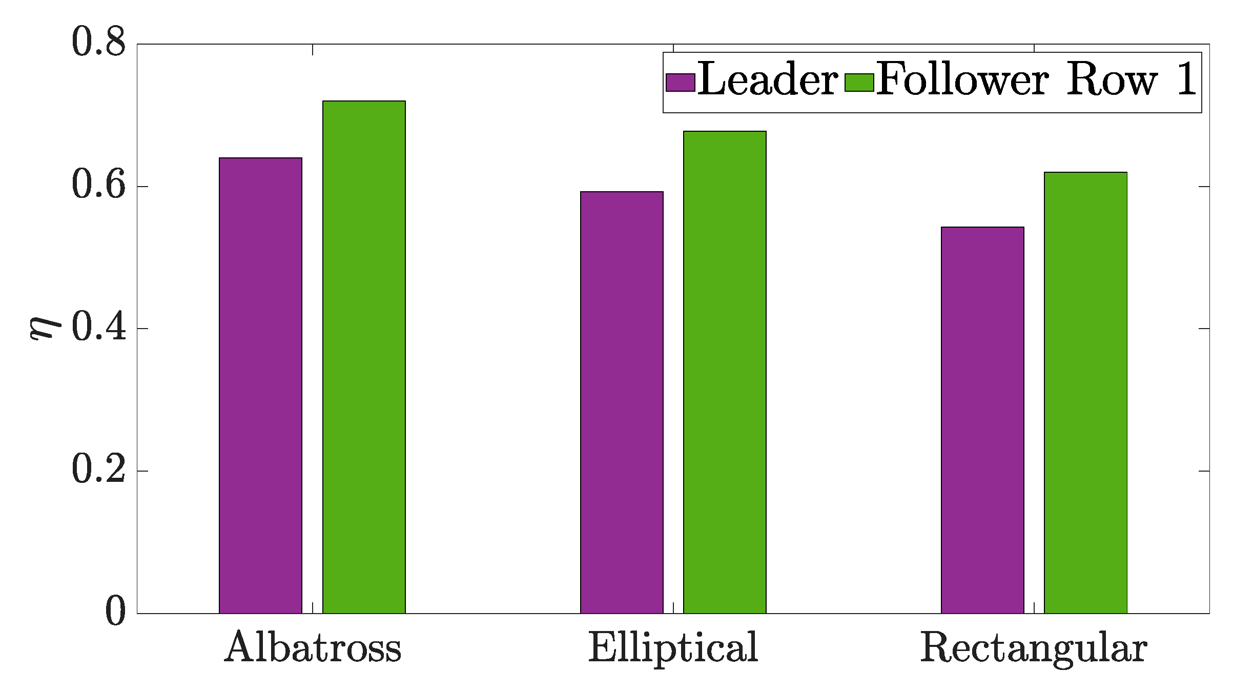
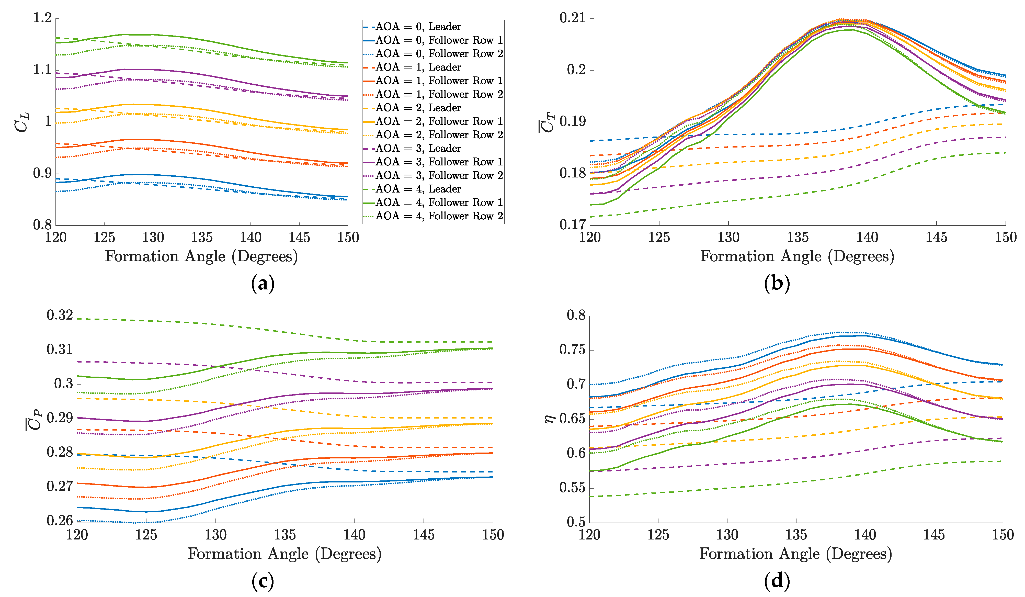
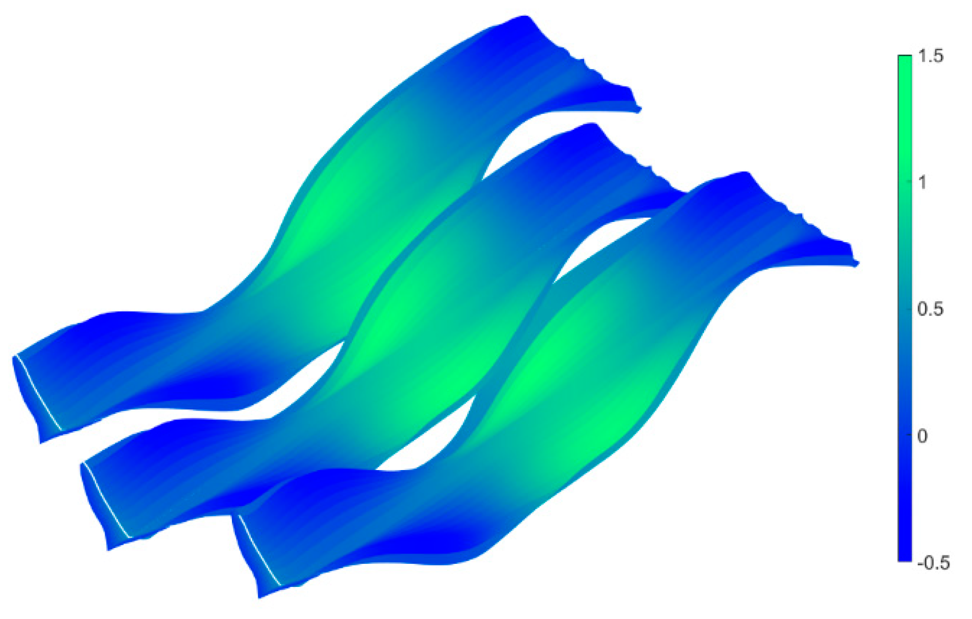
4.3. Comparative Efficiency Study between the 3- and 5-Member Flapping-Wing Configurations

As stated previously, the optimal selection for both the 3- and 5-member configurations is found to be the combination of the formation angle and angle of attack that prioritizes the propulsive efficiency of the follower using the albatross wing shape. A summary of these results is shown in Table 10. Here, it is evident that the global propulsive efficiency is higher for the 5-member configuration compared to the 3-member configuration for all weight estimations. However, the total weight of each estimation is higher for the 5-member configuration compared to that of the 3-member configuration. In addition, the wake plots for these optimal 3- and 5-member configurations using the albatross wing shape corresponding to the baseline +25% weight estimation are shown in Figure 12 and Figure 13, respectively. The wakes in these figures correspond to the history of the vorticity generated over the flapping cycle by the members in each formation.

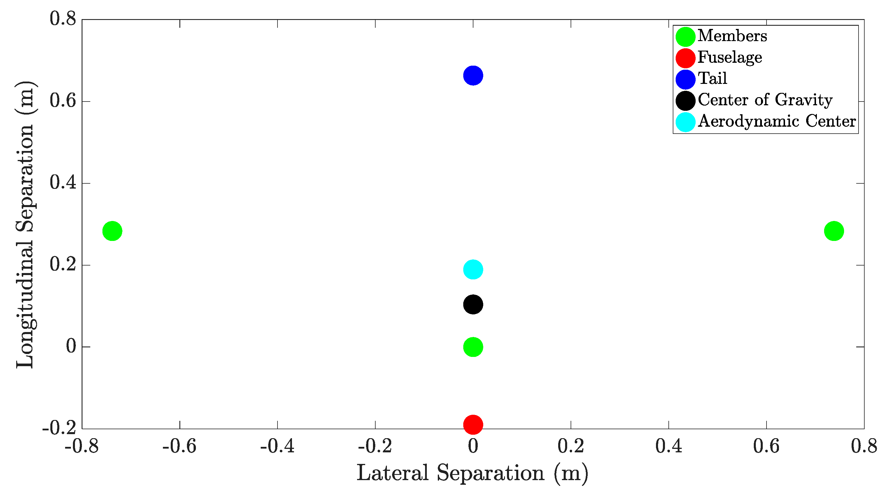
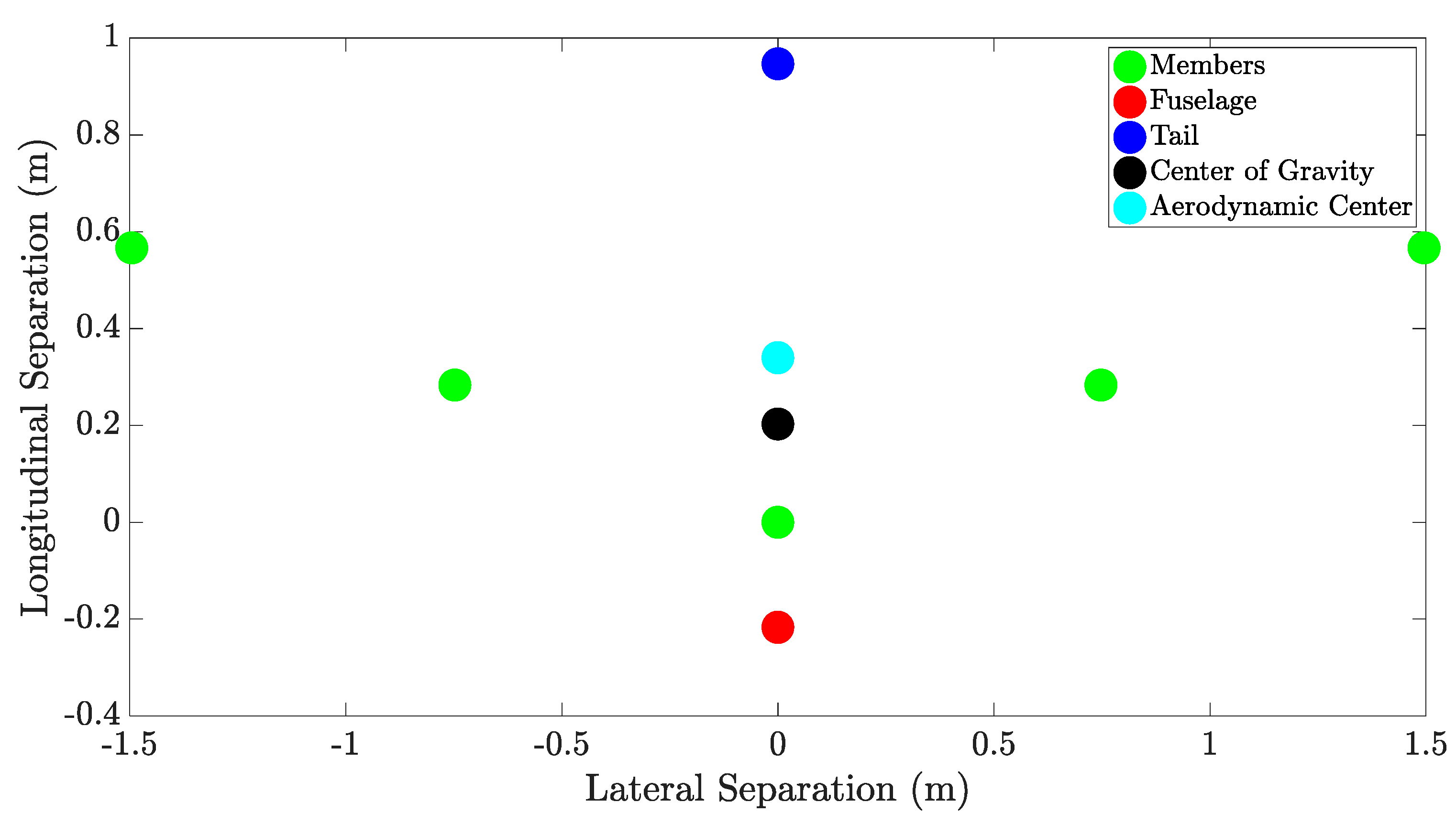
5. Stability Analysis and Tail Sizing

After determining the appropriate wing shape, airfoil, and formation angle, a 2-D stability analysis is conducted based on the separation of the fuselage, tail, and flapping wings. The purpose of this analysis is to estimate the position of the aerodynamic center relative to the center of gravity and to determine the length of the tail arm for the tail sizing process. Each of the main components are arranged from a top-down perspective based on the number of members, formation angle, separation distance, and the approximated location of the fuselage and tail. For the 3-member configuration, the fuselage is placed 19 cm in front of the leader, while the tail is placed 38 cm behind the follower row. For the 5-member configuration, the fuselage is placed 22 cm in front of the leader, and the tail is placed 38 cm behind the second follower row. These values for the tail and fuselage in each configuration are estimated based on their positions relative to the leader and last follower row in the CAD model. In this analysis, each of the main components is represented as a point mass, with a percentage of the electrical and structural masses assigned to each component. In this stability analysis, the weights corresponding to the baseline +25% estimation are used for reference. For the structural category, 70% of the weight is distributed evenly among the members, while 10% and 20% are assigned to the fuselage and tail, respectively. For the electrical category, the distribution is based on the weights of each electrical subcategory shown in Table 1 and Table 2. The weight of the brushless motors (powerplant) is distributed evenly among each of the members, while 50% of the avionics are assigned to the tail as servo motors. Then, the other 50% of the avionics, along with the weight of the battery and payload, are assigned to the fuselage.
Assigning the position and the weight of the main component, the center of gravity in the x- and y-directions is estimated as follows:
C G x = W f u s e l a g e x f u s e l a g e + W t a i l x t a i l + i = 1 N W m e m b e r   i x m e m b e r   i W f u s e l a g e + W t a i l + i = 1 N W m e m b e r   i
C G y = W f u s e l a g e y f u s e l a g e + W t a i l y t a i l + i = 1 N W m e m b e r   i y m e m b e r   i W f u s e l a g e + W t a i l + i = 1 N W m e m b e r   i
Here, C G is the center of gravity, W f u s e l a g e represents the weight of the fuselage, W t a i l is the weight of the tail, and W m e m b e r   i denotes the weight of the i t h member in the formation, where N corresponds to the total number of members in the formation. In addition, N is assumed to be odd and greater than or equal to 3. Similarly, x and y for each component corresponds to its estimated lateral and longitudinal position, respectively. These lateral and longitudinal positions are given with respect to the leader, which is placed at the origin.
Next, the location of the aerodynamic center is approximated. To do this, it is assumed that the lift produced by each of the members occurs at the location of their corresponding point mass. Then, the position of the aerodynamic center is given by:
A C x = C ¯ L l e a d e r x m e m b e r   1 + i = 1 ( N 1 ) / 2 C ¯ L r o w   i ( x m e m b e r   2 i + x m e m b e r   2 i + 1 ) C ¯ L l e a d e r + 2 i = 1 ( N 1 ) / 2 C ¯ L r o w   i
A C y = C ¯ L l e a d e r y m e m b e r   1 + i = 1 ( N 1 ) / 2 C ¯ L r o w   i ( y m e m b e r   2 i + y m e m b e r   2 i + 1 ) C ¯ L l e a d e r + 2 i = 1 ( N 1 ) / 2 C ¯ L r o w   i
Here, A C refers to the aerodynamic center, C ¯ L l e a d e r denotes the mean coefficient of lift of the leader, and C ¯ L r o w   i is the mean coefficient of lift of the ith follower row. Furthermore, x m e m b e r   n and y m e m b e r   n correspond to the location of the nth member in the formation. In this analysis, the values for C ¯ L l e a d e r and C ¯ L r o w   i are obtained from the efficiency-prioritized albatross simulations at the baseline +25% weight estimation. Using Equations (12) and (13) for the 3-member configuration, the positions of the center of gravity and aerodynamic center are estimated. For the 3-member configuration, the tail arm is calculated as 47.41 cm, while the center of gravity is located 8.53 cm in front of the aerodynamic center. To clarify, the tail arm is estimated as the longitudinal distance between the aerodynamic center and the point mass representation of the tail. Figure 14 corresponds to a 3-member configuration and shows the relative position of the wings, fuselage, and tail from a top-down view. The formation angle is selected based on the efficiency-prioritized results for the albatross wing shape at the baseline +25% weight estimation reported in Table 4. In addition, Figure 14 shows the calculated positions of the center of gravity and aerodynamic center.
Next, the locations of the aerodynamic center and center of gravity are estimated for the 5-member configuration. Following the same procedure used for the 3-member configuration, Figure 15 shows the layout of the 5 members in addition to the position of the fuselage and tail. The formation angle used for arranging the members is selected based on the efficiency-prioritized results at the baseline +25% weight estimation for the albatross wing shape reported in Table 7. For this configuration, the tail arm is found equal to 60.68 cm, while the center of gravity is located 13.7 cm in front of the aerodynamic center. These results indicate that the center of gravity is placed in front of the aerodynamic center for both configurations.
Following the sizing approach presented in [33], the tails are sized using the following equations:
S v e r t i c a l = N C V b S w i n g / L
S h o r i z o n t a l = N C H c ¯ S w i n g / L
where S v e r t i c a l and S h o r i z o n t a l denote the vertical and horizontal surface areas of the tail, respectively. In addition, N is the number of members in the formation, C V is the vertical tail volume coefficient, C H is the horizontal tail volume coefficient, S w i n g is the surface area of the wing, and L is the length of the tail arm. Finally, b is the wingspan and c ¯ is the standard mean chord, which is the ratio of the wing surface area over the wingspan.
In general, the horizontal tail volume coefficient varies by aircraft type between 0.5 and 1.0, while the vertical tail volume coefficient varies between 0.02 and 0.09 [34]. For the purpose of this work, the horizontal and vertical tail volume coefficients are assumed to lie within the ranges 0.5–0.7 and 0.02–0.04, respectively. Using Equations (16) and (17) along with the assumed ranges for the tail volume coefficients, a range for the expected surface areas for each configuration is calculated. For the 3-member configuration, the horizontal and vertical surface areas are found within 0.0174–0.0244 m2 and 0.0074–0.0147 m2, respectively. Likewise, for the 5-member configuration, the horizontal and vertical surface areas are found within 0.0227–0.0317 m2 and 0.0096–0.0192 m2, respectively. Given these ranges, a tail is designed for both the 3-member and 5-member configurations of the MFWD, and the dimensions are selected based on the expected range for the horizontal and vertical surface areas. For the 3-member configuration, the resulting horizontal and vertical surface areas are 0.0225 m2 and 0.0113 m2, respectively, and fall within the expected ranges. For the 5-member configuration, the calculated horizontal and vertical surface areas are 0.0288 m2 and 0.0144 m2, respectively. These values also fall within the expected ranges. Figure 16 illustrates the tail designs for the two MFWD configurations. The rudder and elevons are held in place with a pin and are actuated by servo motors and linkages. It should be noted that a dedicated servo motor is assigned to each elevon and the rudder to allow pitch, roll, and yaw control of the drone. To mount these servos, a bracket is designed and attached to the tail arm about 2 cm in front of the tail.

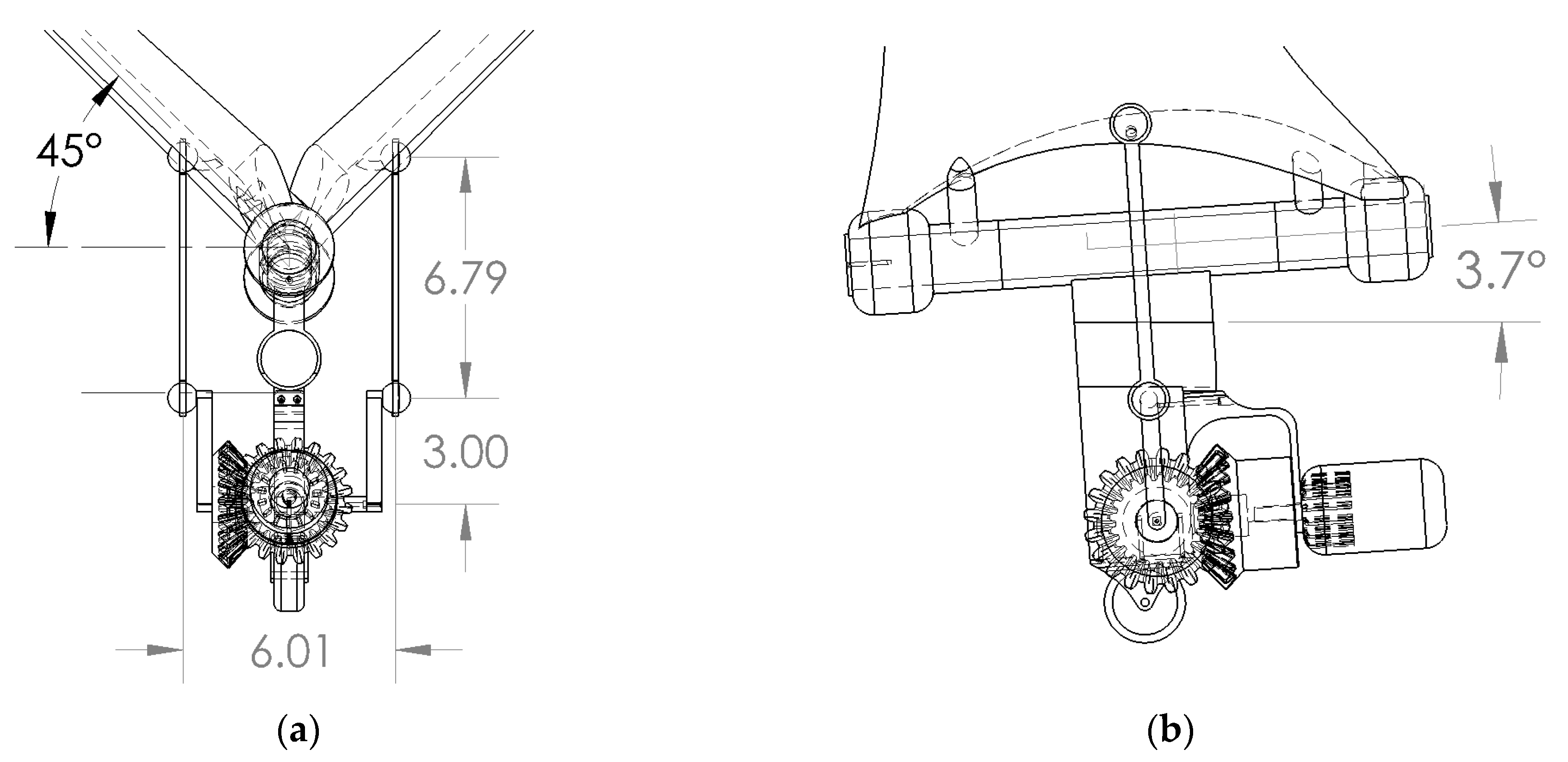
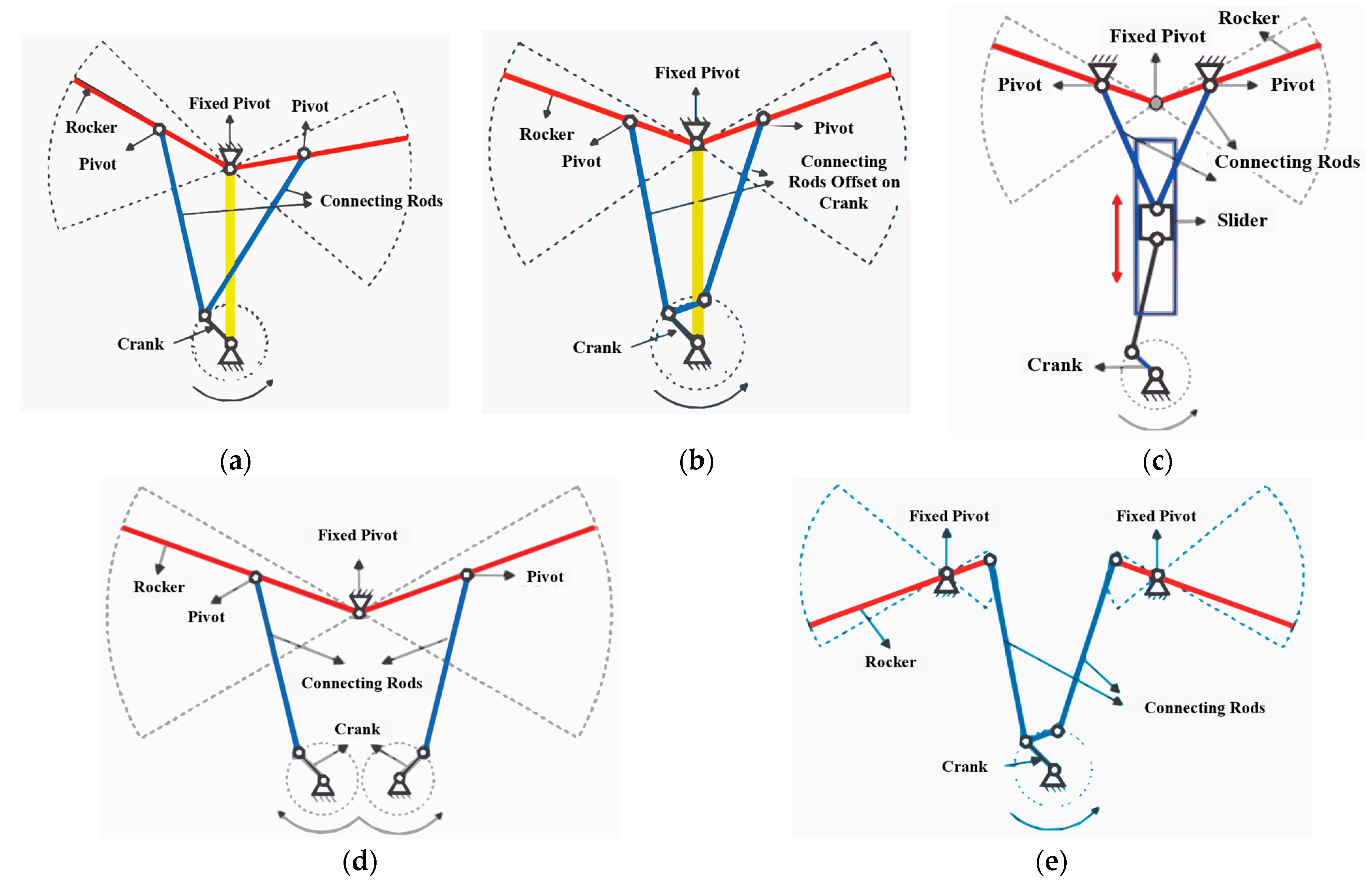
6. Flapping Mechanism Selection

As noted previously, the aerodynamic solver used a flapping frequency of 3 Hz at an amplitude of 45 degrees for the flapping motion of the wings. Furthermore, the flapping motion is prescribed using the wing root as the pivot point. Therefore, this amplitude and pivot point are two of the main constraints for the design of the flapping mechanism. Different types of mechanisms, shown in Figure 17, are investigated to determine the benefits and drawbacks of each. Each of the mechanisms listed in this section is discussed in a comprehensive review by Hassanalian and Abdelkefi [35]. Figure 17a illustrates a single crank mechanism with two rockers connected to a single pivot on the crank at one end, and connected to each of the wings at the other. Furthermore, the flapping pivot is located at the root of the wings, which is the case for Figure 17b–d as well. The benefit of this arrangement is that it is the simplest and has light weight. However, a significant drawback of this design is that the flapping motion is neither harmonic nor symmetric [36,37]. Figure 17b demonstrates a single crank mechanism with an offset, which allows for a more symmetric flapping motion and limits the phase difference between the flapping wings. However, the rockers may cross over each other near the connection at the crank when they are at the same vertical plane [36,38]. Next, Figure 17c shows a slider crank mechanism. This design incorporates a single linkage connected to the crank, which in turn connects at the other end to a piston. This piston is constrained to vertical displacement and has two connected rockers which allow the wings to flap. This mechanism allows for symmetric flapping motion and avoids the issue of potential rocker overlap present in crank with offset shown in Figure 17b. However, some notable drawbacks are that this system is more difficult to fabricate, and that frictional energy loss is more prevalent due to the piston-slider assembly [36,38,39]. The double crank mechanism shown in Figure 17d uses two symmetric cranks, each with its own rocker attached to the flapping wing. These cranks may be kept in phase using meshed gears between them, which allows for the symmetric flapping motion. However, one drawback is that this design results in an increased weight. Additionally, the two gears meshing the crankshafts together may slip due to the backlash from the flapping motion, which in turn may cause the wings to become out of phase [36,37,38,40]. Finally, an alternate configuration for the flapping mechanism is shown in Figure 17e, which uses a single crank with an offset, similar to the design shown in Figure 17b. However, this alternate configuration has an independent flapping pivot for each of the wings, which is offset from the centerline. This design allows for the same flapping motions as the other options, but also results in a nonsymmetric profile for the mechanism. Additionally, the introduction of the offset flapping pivot makes this arrangement impractical for a FWMAV using a biplane configuration [36,41]. Both the advantages and disadvantages of each mechanism illustrated in Figure 17 are summarized in Table 11.
Based on the advantages and disadvantages of each mechanism, the double crank design is selected as the reference for this work. The primary reason for this selection is the capability to produce a symmetric flapping motion and including the central pivot at the root of the wings, which was the case for all simulations. In addition, the double crank mechanism avoids the issue of excess friction present in the slider crank mechanism. However, the drawback of complicated assembly and the potential for gear slippage still needs to be addressed. To resolve both of these issues at once, a single lateral crankshaft is proposed instead of the two longitudinal crankshafts. This single crankshaft eliminates the meshing gears entirely and ensures that the wings are always in phase while also reducing complexity of design. This lateral crankshaft has ball joints at the end, which allow for the connection of rocker linkages to the ball joints mounted on the underside of the wings. To drive this mechanism, a brushless motor is mounted on a bracket placed at the same plane as the pivoting axis. Then, two bevel gears are introduced to redirect the rotation from the motor to the crankshaft [42]. In this way, the wings will remain in phase even in the unlikely event that gear slippage occurs. The design of this mechanism is illustrated in Figure 18.
Next, the 45-degree flapping amplitude is implemented in this flapping mechanism. To ensure that this flapping amplitude can be achieved, care is taken to determine the appropriate dimensions for the crankshaft and connecting rockers. The key dimensions for these components are shown in Figure 19a. In addition, the appropriate angle of attack determined from the aerodynamic analysis is included in the design. To this end, a 16 mm hole is added to the central mount, and its centerline is inclined at a 3.7-degree angle relative to the centerline of the pivot. This angle ensures that the wings are mounted at the appropriate angle of attack. In this assembly, the angle is selected based on the baseline +25% weight estimation for the efficiency-prioritized albatross simulations.

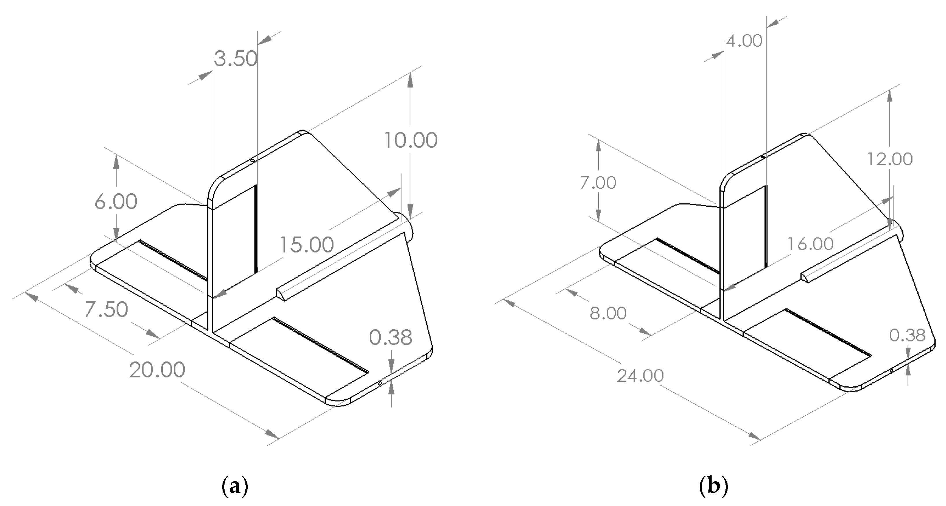
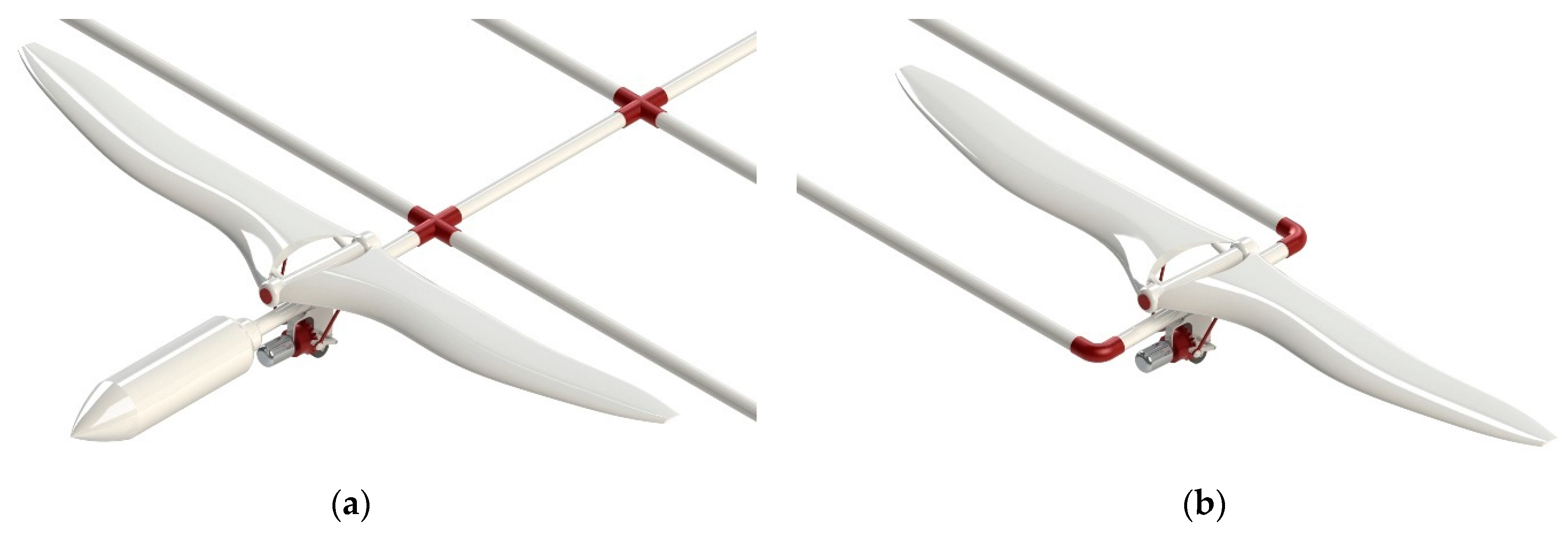
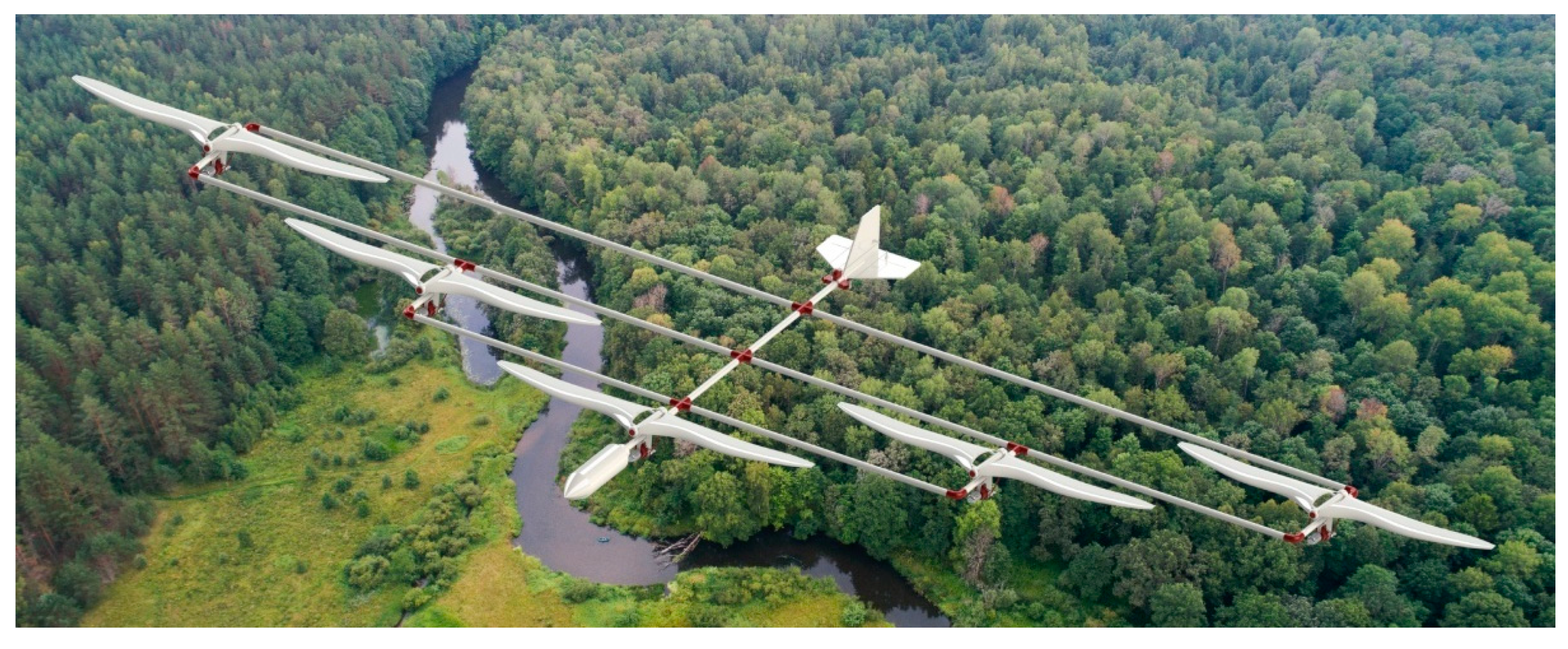
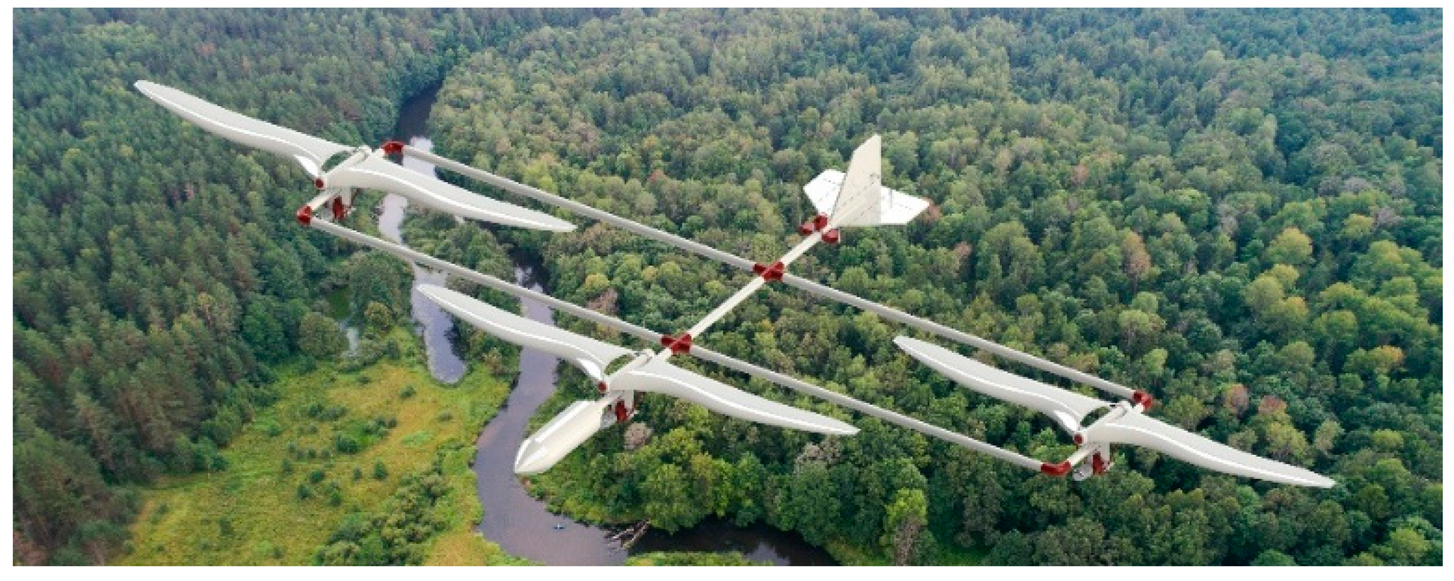
7. Final Designs of Bioinspired Multi-Flapping Wings Drones

In this section, the final conceptual designs for the multi-flapping-wing drones are proposed. The design of the 3-member configuration is illustrated in Figure 20. In this design, several unique features are implemented. First, each of the flapping wings are arranged using the lateral separation distance and formation angle obtained from the aerodynamic analysis (optimal configuration based on efficiency-prioritized albatross simulations). For ease of assembly, each of the flapping wings is contained in a “module”, which consists of the wings, flapping mechanism, brushless motor, and landing wheel. The flapping modules are easily interchangeable for ease of adjustment and reparability. A close-up view of these modules is shown in Figure 21. Furthermore, the modules are arranged at the appropriate separation distance and formation angle using 16 mm carbon fiber tubing, which is held together using elbows and cross connectors. Furthermore, a single fuselage is mounted directly in front of the leader by attaching it to the end of the carbon fiber support. The fuselage has a conical, hollow design to reduce drag and to fit the main electrical components such as the battery, receiver, and ESC. Additionally, a flight computer may be included in the fuselage if autopilot is desired. Next, the tail is mounted on a carbon fiber support behind the follower row. The elevons and rudder are actuated with independent servos and linkages which are attached to the support in front of the tail. The primary function of this tail is to control roll and pitch with the elevons and yaw with the rudder.
In addition to the 3-member configuration, the final conceptual design for the 5-member configuration of the MFWD is proposed, as illustrated in Figure 22. This design incorporates another follower row, which allows for higher payload capacity compared to the 3-member design. In addition, a larger tail is included in this design as discussed in Section 5. Furthermore, the fuselage size is increased by 10% to accommodate a larger battery for powering the brushless motors in the additional follower modules. It should be noted that this design also incorporates T-connectors for assembling the carbon fiber support tubing. Similar to the 3-member design, all of the lateral supports are made of a single carbon fiber tube to increase rigidity. In addition, both designs are easily customizable to make the appearance more discrete. For example, artificial feathers may be applied to the flapping modules, while the fuselage, tail, and structural tubing may be painted to blend in more seamlessly with the atmosphere. This ease of customization along with the bioinspired appearance makes this design ideal for reconnaissance applications. Finally, the unique advantages for each of these designs, as well as the general features of the MFWD, are presented in Table 12.

8. Conclusions

In this work, a bioinspired design for novel multi-flapping-wing drones which exploits the aerodynamic benefits of V-formation flights was proposed and investigated. A mission plan was first selected and described followed by drone sizing and weight estimation. Next, aerodynamic simulations were generated using the unsteady vortex lattice method to determine the appropriate wing shape and airfoil profile. Furthermore, this aerodynamic analysis was used to determine the combination of the angle of attack and formation angle that maximizes the follower propulsive efficiency for both a 3- and 5-member group size. The aerodynamic simulations revealed that the albatross wing shape using the Selig 1223 airfoil was the most effective choice for both the 3-member and 5-member drones’ designs. In addition, a static stability analysis was conducted to ensure that the center of gravity is placed in front of the aerodynamic center, and to determine the length of the tail arm based on the relative positions of the aerodynamic center and the tail. This tail arm was then used in a tail sizing procedure for both configurations. An investigation on various flapping mechanisms was then conducted to ensure the generation of symmetric flapping motion. A modified version of the double crank mechanism was selected due to its symmetric design. A single lateral crankshaft was implemented instead of two crankshafts to limit the weight and prevent the potential for out-of-phase flapping motion. Finally, the formation angle and angle of attack corresponding to the highest endurance were determined and implemented into the prototypes’ models. The goal of this work was to provide a framework for the conceptual design of a multi-flapping-wing drone, and to demonstrate the sizing, weight estimation, and design procedures for this new type of flapping-wing system. It should be mentioned that the proposed design has some limitations which pose challenges for its implementations. For instance, any asymmetry in the air vehicle due to misalignment of the components or frequency shift in the flapping motion of the wings may significantly impact the flight. As such, all flapping wings need to operate in a synchronized way. Another limitation is the potential for roll instability due to slight asymmetry in the weight distribution with respect to the longitudinal centerline. In addition, slight phase discrepancies between the flapping cycle of each module may induce unwanted vibration, resulting in instability and degradation in the flight performance. Therefore, care should be taken during the fabrication process to ensure sufficient synchronization of the wings, even weight distribution, and selection of the support thickness to ensure high rigidity.

Author Contributions

Conceptualization, E.B., M.G., R.V., and A.A.; methodology, E.B., M.G., R.V., and A.A.; software, E.B. and M.G.; validation, E.B. and M.G.; formal analysis, E.B.; investigation, E.B.; resources, M.G. and A.A.; data curation, E.B.; writing—original draft preparation, E.B.; writing—review and editing, M.G., R.V., and A.A.; supervision, M.G., R.V., and A.A.; project administration, A.A. All authors have read and agreed to the published version of the manuscript.

Funding

This research received no external funding.

Data Availability Statement

The data that support the findings of this study are available upon reasonable request from the authors.

Acknowledgments

This work utilized resources from the New Mexico State University High Performance Computing Group, which is directly supported by the National Science Foundation (OAC-2019000), the Student Technology Advisory Committee, and New Mexico State University and benefits from inclusion in various grants (DoD ARO-W911NF1810454; NSF EPSCoR OIA-1757207; Partnership for the Advancement of Cancer Research, supported in part by NCI grants U54 CA132383 (NMSU)). R. Vasconcellos acknowledges the financial support of the Brazilian agency CAPES (grant 88881.302889/2018-01).

Conflicts of Interest

The authors declare that they have no conflict of interest.

References

  1. Hassanalian, M.; Abdelkefi, A.; Wei, M.; Ziaei-Rad, S. A novel methodology for wing sizing of bio-inspired flapping wing micro air vehicles: Theory and prototype. Acta Mech. 2016, 228, 1097–1113. [Google Scholar] [CrossRef]
  2. Hassanalian, M.; Abdelkefi, A. Methodologies for weight estimation of fixed and flapping wing micro air vehicles. Meccanica 2017, 52, 2047–2068. [Google Scholar] [CrossRef]
  3. Chen, C.; Zhang, T. A Review of Design and Fabrication of the Bionic Flapping Wing Micro Air Vehicles. Micromachines 2019, 10, 144. [Google Scholar] [CrossRef] [Green Version]
  4. Yang, W.; Wang, L.; Song, B. Dove: A biomimetic flapping-wing micro air vehicle. Int. J. Micro Air Veh. 2018, 10, 70–84. [Google Scholar] [CrossRef]
  5. Lee, J.; Ryu, S.; Kim, H.J. Stable Flight of a Flapping-Wing Micro Air Vehicle Under Wind Disturbance. IEEE Robot. Autom. Lett. 2020, 5, 5685–5692. [Google Scholar] [CrossRef]
  6. BionicOpter, Festo Corporate. Available online: https://www.festo.com/group/en/cms/10224.htm (accessed on 15 July 2021).
  7. Lane, P.; Throneberry, G.; Fernandez, I.; Hassanalian, M.; Vasconcellos, R.; Abdelkefi, A. Towards Bio-Inspiration, Development, and Manufacturing of a Flapping-Wing Micro Air Vehicle. Drones 2020, 4, 39. [Google Scholar] [CrossRef]
  8. Nguyen, Q.-V.; Chan, W.L. Development and flight performance of a biologically-inspired tailless flapping-wing micro air vehicle with wing stroke plane modulation. Bioinspiration Biomim. 2018, 14, 016015. [Google Scholar] [CrossRef]
  9. Explorer, DelFly. Available online: http://www.delfly.nl/explorer/ (accessed on 15 July 2021).
  10. Ryu, S.; Kim, H.J. Development of a flapping-wing micro air vehicle capable of autonomous hovering with onboard measurements. In Proceedings of the 2017 IEEE/RSJ International Conference on Intelligent Robots and Systems (IROS), Vancouver, BC, Canada, 24–28 September 2017; pp. 3239–3245. [Google Scholar]
  11. Jones, K.D.; Bradshaw, C.J.; Papadopoulos, J.; Platzer, M.F. Bio-inspired design of flapping-wing micro air vehicles. Aeronaut. J. 2015, 109, 385–393. [Google Scholar] [CrossRef]
  12. Lissaman, P.B.S.; Shollenberger, C.A. Formation Flight of Birds. Science 1970, 168, 1003–1005. [Google Scholar] [CrossRef]
  13. Cutts, C.J.; Speakman, J.R. Energy savings in formation flight of pink-footed geese. J. Exp. Biol. 1994, 189, 251–261. [Google Scholar] [CrossRef] [PubMed]
  14. Gould, L.L.; Heppner, F. The vee formation of Canada geese. Auk 1974, 91, 494–506. [Google Scholar]
  15. Völkl, B.; Fritz, J. Relation between travel strategy and social organization of migrating birds with special consideration of formation flight in the northern bald ibis. Philos. Trans. R. Soc. B Biol. Sci. 2017, 372, 20160235. [Google Scholar] [CrossRef]
  16. Hummel, D. The use of aircraft wakes to achieve power reductions in formation flight. In Proceedings of the AGARD FDP Symposium on The Characterization & Modification of Wakes from Lifting Vehicles in Fluid, Trondheim, Norway, 20–23 May 1996. [Google Scholar]
  17. Weimerskirch, H.; Martin, J.; Clerquin, Y.; Alexandre, P.; Jiraskova, S. Energy saving in flight formation. Nature 2001, 413, 697–698. [Google Scholar] [CrossRef]
  18. Ghommem, M.; Calo, V.M. Flapping wings in line formation flight: A computational analysis. Aeronaut. J. 2014, 118, 485–501. [Google Scholar] [CrossRef]
  19. Tay, W.-B.; Murugaya, K.R.; Chan, W.-L.; Khoo, B.-C. Numerical Simulation of Flapping Wing MAVs in V-formation. J. Bionic Eng. 2019, 16, 264–280. [Google Scholar] [CrossRef]
  20. Zhu, X.; Bian, C.; Chen, Y.; Chen, S. A low latency clustering method for large-scale drone swarms. IEEE Access 2019, 7, 186260–186267. [Google Scholar] [CrossRef]
  21. Mashood, A.; Mohammed, M.; Abdulwahab, M.; Abdulwahab, S.; Noura, H. A hardware setup for formation flight of UAVs using motion tracking system. In Proceedings of the 2015 10th International Symposium on Mechatronics and Its Applications (ISMA), Sharjah, United Arab Emirates, 8–10 December 2015; pp. 1–6. [Google Scholar]
  22. Min, S.; Nam, H. A formation flight control of UAVs using ZigBee. In Proceedings of the 2016 13th International Conference on Ubiquitous Robots and Ambient Intelligence (URAI), Xi’an, China, 19–22 August 2016; pp. 163–165. [Google Scholar]
  23. Kartal, Y.; Subbarao, K.; Gans, N.R.; Dogan, A.; Lewis, F.L. Distributed backstepping based control of multiple UAV formation flight subject to time delays. IET Control Theory Appl. 2020, 14, 1628–1638. [Google Scholar] [CrossRef]
  24. Stanford, B.K.; Beran, P.S. Analytical Sensitivity Analysis of an Unsteady Vortex-Lattice Method for Flapping-Wing Optimization. J. Aircr. 2010, 47, 647–662. [Google Scholar] [CrossRef]
  25. Ghommem, M.; Hajj, M.R.; Mook, D.T.; Stanford, B.K.; Beran, P.S.; Snyder, R.D.; Watson, L.T. Global optimization of actively morphing flapping wings. J. Fluids Struct. 2012, 33, 210–228. [Google Scholar] [CrossRef]
  26. Nguyen, A.T.; Kim, J.-K.; Han, J.-S.; Han, J.-H. Extended unsteady vortex-lattice method for insect flapping wings. J. Aircr. 2016, 53, 1709–1718. [Google Scholar] [CrossRef]
  27. Roccia, B.A.; Preidikman, S.; Massa, J.C.; Mook, D.T. Modified unsteady vortex-lattice method to study flapping wings in hover flight. AIAA J. 2013, 51, 2628–2642. [Google Scholar] [CrossRef] [Green Version]
  28. Pennycuick, C. Wingbeat frequency of birds in steady cruising flight: New data and improved predictions. J. Exp. Biol. 1996, 199, 1613–1618. [Google Scholar] [CrossRef] [PubMed]
  29. Drofelnik, J.; Da Ronch, A.; Kharlamov, D.; Sun, Y. Rapid calculation of unsteady aircraft loads. In Proceedings of the 7th European Conference on Computational Fluid Dynamics, Glasgow, UK, 11–15 June 2018; p. 2108. [Google Scholar]
  30. Katz, J.; Plotkin, A. Low-Speed Aerodynamics; Cambridge University Press: Cambridge, UK, 2001. [Google Scholar]
  31. MathWorks. Image Processing Toolbox. Available online: https://mathworks.com/help/images (accessed on 15 July 2021).
  32. Airfoil Tools Database. Available online: https://airfoiltools.com (accessed on 15 July 2021).
  33. Ghommem, M.; Hassanalian, M.; Al-Marzooqi, M.; Throneberry, G.; Abdelkefi, A. Sizing process, aerodynamic analysis, and experimental assessment of a biplane flapping wing nano air vehicle. Proc. Inst. Mech. Eng. Part G J. Aerosp. Eng. 2019, 233, 5618–5636. [Google Scholar] [CrossRef]
  34. Concept of Tail Volumes to Size Horizontal and Vertical Tails. Available online: https://gatepathshala.com/pdf/download/conceptoftailvolumestosizehorizontalandverticaltails.pdf (accessed on 15 July 2021).
  35. Hassanalian, M.; Abdelkefi, A. Towards improved hybrid actuation mechanisms for flapping wing micro air vehicles: Analytical and experimental investigations. Drones 2019, 3, 73. [Google Scholar] [CrossRef] [Green Version]
  36. Gerrard, C.; Ward, M. Final Year Honours Project Micro Air Vehicle; The University of Adelaide: Adelaide, Australia, 2007. [Google Scholar]
  37. Singh, S.M. Flapping wings, a theoretical approach. Int. J. Eng. Sci. Adv. Technol. 2014, 4, 220–225. [Google Scholar]
  38. Benedict, M.; Sudhakar, K.; Issac, K.K. Aeroelastic Design and Manufacture of an Efficient Ornithopter Wing; Department of Aerospace Engineering, Indian Institute of Technology: Bombay, Mumbai, India, 2004. [Google Scholar]
  39. Yusoff, H.; Abdullah, M.Z.; Mujeebu, M.A.; Ahmad, K.A. Development of flexible wings and flapping mecha-nism with integrated electronic control system, for micro air vehicle research. Exp. Tech. 2013, 37, 25–37. [Google Scholar] [CrossRef]
  40. Liu, L.; Fang, Z.; He, Z. Optimization design of flapping mechanism and wings for flapping-wing MAVs. In Proceedings of the Computer-Nat Visional Conference on Intelligent Robotics and Applications, Newcastle, NSW, Australia, 9–11 August 2008; Springer: Berlin, Heidelberg, 2008; pp. 245–255. [Google Scholar]
  41. Beasley, B. A Study of Planar and Nonplanar Membrane Wing Planforms for the Design of a Flapping-Wing Micro Air Vehicle. Master’s thesis, Department of Aerospace Engineering, University of Maryland, College Park, MA, USA, 2006. [Google Scholar]
  42. McMaster-Carr Miter Gear Catalog. Available online: https://www.mcmaster.com/gears/plastic-miter-gears/ (accessed on 15 July 2021).
Figure 1. Mission plan description. Steps include takeoff, ascension to cruising altitude, area sweep, target acquisition, descension, and landing.
Drones 05 00064 g001
Figure 2. (a) Albatross, (b) elliptical, and (c) rectangular wing shapes used for planform variety.
Drones 05 00064 g002
Figure 3. Selig 1223 and NACA 0012 airfoils selected for camber variety [32].
Drones 05 00064 g003
Figure 4. Top-down view of five members flying in V-formation. Here, α corresponds to the formation angle and X r e l corresponds to the lateral separation distance. Each follower row consists of two members.
Drones 05 00064 g004
Figure 5. Total lift produced for each wing shape using the NACA 0012 camber line. A 3-member V-formation is used for each wing shape.
Drones 05 00064 g005
Figure 6. Total lift produced by a 3-member V-formation of each wing shape over a range of formation angles and angles of attack. The dark, transparent planes correspond to the base weight estimation as well as the two overestimations of 10% and 25%.
Drones 05 00064 g006
Figure 7. Average coefficient of (a) lift, (b) thrust, (c) power, and (d) propulsive efficiency over a range of formation angles for the leader and the first follower row using the albatross wing shape. The angle of attack is varied between 0 and 7 degrees.
Drones 05 00064 g007
Figure 8. Leader and follower row 1 propulsive efficiency for the three considered wing shapes corresponding to the formation angle and angle of attack when prioritizing efficiency at the baseline +10% weight estimation.
Drones 05 00064 g008
Figure 9. Total lift produced by a 5-member V-formation of each wing shape over a range of formation angles and angles of attack. The dark, transparent planes correspond to the base weight estimation as well as the two overestimations of 10% and 25%.
Drones 05 00064 g009
Figure 10. Average coefficient of (a) lift, (b) thrust, (c) power, and (d) propulsive efficiency over a range of formation angles for the leader and follower rows 1 and 2 using the albatross wing shape.
Drones 05 00064 g010
Figure 11. Propulsive efficiency of the leader and follower rows 1 and 2 for each wing shape corresponding to the formation angle and angle of attack when prioritizing efficiency at the base +10% weight estimation.
Drones 05 00064 g011
Figure 12. Wake vortices produced by the albatross wing shape in a 3-member V-formation, where the color corresponds to the vorticity strength.
Drones 05 00064 g012
Figure 13. Wake vortices produced by the albatross wing shape in a 5-member V-formation, where the color corresponds to the vorticity strength.
Drones 05 00064 g013
Figure 14. Location of each pair of flapping wings in a 3-member formation along with the position of the fuselage, tail, center of gravity, and aerodynamic center. The center of gravity is found to be in front of the aerodynamic center.
Drones 05 00064 g014
Figure 15. Location of each pair of flapping wings in a 5-member formation along with the position of the fuselage, tail, center of gravity, and aerodynamic center. The center of gravity is found to be in front of the aerodynamic center.
Drones 05 00064 g015
Figure 16. Tail dimensions (in centimeters) for the (a) 3-member and (b) 5-member MFWD configurations.
Drones 05 00064 g016
Figure 17. (a) Single crank, (b) crank with offset, (c) slider-crank, (d) double crank, and (e) alternate configuration flapping mechanisms discussed in [35].
Drones 05 00064 g017
Figure 18. (a) Top-isometric and (b) bottom-isometric views of the flapping mechanism designed for the MFWD. This design is a variation on the double crank mechanism discussed in [35] and uses a single crank instead of meshed gears to prevent slippage.
Drones 05 00064 g018
Figure 19. (a) Front and (b) side drawings of the MFWD flapping mechanism with key dimensions shown in centimeters.
Drones 05 00064 g019
Figure 20. Final conceptual design of the 3-member bioinspired multi-flapping-wing drone.
Drones 05 00064 g020
Figure 21. Close-up view of the (a) leading member and (b) port following member in the 3-member MFWD design.
Drones 05 00064 g021
Figure 22. Final conceptual design of the 5-member multi-flapping-wing drone.
Drones 05 00064 g022
Table 1. The 3-member MFWD weight estimation and breakdown by category.
3-Member DronePowerplantPayloadBatteryAvionicsStructuralTotal
Base weight est. (g)120.47.5105.367.7526.7827.6
Weight est. (g) + 10%120.47.5188.167.7526.7910.4
Weight est. (g) + 25%120.47.5312.267.7526.71034.5
Table 2. The 5-member MFWD weight estimation and breakdown by category.
5-Member DronePowerplantPayloadBatteryAvionicsStructuralTotal
Base weight Est. (g)200.612.5175.6112.9877.81379.4
Weight est. (g) + 10%200.612.5313.5112.9877.81517.3
Weight est. (g) + 25%200.612.5520.4112.9877.81724.2
Table 3. UVLM simulation parameters.
Wingspan0.85 m
Surface area0.0684 m2
Following distance0.283 m
Velocity8.5 m/s
Flapping amplitude45 degrees
Flapping frequency3 Hz
Table 4. Formation angle, angle of attack, and global propulsive efficiency for the albatross wing shape in a 3-member formation corresponding to the total lift required to meet each of the proposed weight estimations when prioritizing either lift or efficiency.
Albatross
3 Members
Peak Follower LiftPeak Follower Efficiency
Base Est.+10%+25%Base Est.+10%+25%
Weight estimation827.7 g910.5 g1034.7 g827.7 g910.5 g1034.7 g
Formation angle129129128.5139139138
Angle of attack0.17931.51503.52290.37261.73033.7364
Global efficiency0.69390.66130.59930.71370.68000.6178
Table 5. Formation angle, angle of attack, and global propulsive efficiency for the elliptical wing shape in a 3-member formation corresponding to the total lift required to meet each of the proposed weight estimations when prioritizing either lift or efficiency.
Elliptical
3 Members
Peak Follower LiftPeak Follower Efficiency
Base Est.+10%+25%Base Est.+10%+25%
Weight estimation827.7 g910.5 g1034.7 g827.7 g910.5 g1034.7 g
Formation angle127127127138138138
Angle of attack0.29611.62913.63290.49111.84093.8728
Global efficiency0.64840.61260.54780.67180.63490.5688
Table 6. Formation angle, angle of attack, and global propulsive efficiency for the rectangular wing shape in a 3-member formation corresponding to the total lift required to meet each of the proposed weight estimations when prioritizing either lift or efficiency.
Rectangular
3 Members
Peak Follower LiftPeak Follower Efficiency
Base Est.+10%+25%Base Est.+10%+25%
Weight estimation827.7 g910.5 g1034.7 g827.7 g910.5 g1034.7 g
Formation angle128128128141141141
Angle of attack1.09342.43794.47201.26162.62834.6898
Global efficiency0.59260.56050.50040.61480.58130.5228
Table 7. Formation angle, angle of attack, and global propulsive efficiency for the albatross wing shape in a 5-member formation corresponding to the total lift required to meet each of the proposed weight estimations when prioritizing either lift or efficiency.
Albatross
5 Members
Peak Follower LiftPeak Follower Efficiency
Base Est.+10%+25%Base Est.+10%+25%
Weight estimation1379.5 g1517.5 g1724.4 g1379.5 g1517.5 g1724.4 g
Formation angle129128128.5140138138.5
Angle of attack0.07811.41023.42180.39361.66313.7254
Global efficiency0.70730.67430.61930.73830.71000.6501
Table 8. Formation angle, angle of attack, and global propulsive efficiency for the elliptical wing shape in a 5-member formation corresponding to the total lift required to meet each of the proposed weight estimations when prioritizing either lift or efficiency.
Elliptical
5 Members
Peak Follower LiftPeak Follower Efficiency
Base Est.+10%+25%Base Est.+10%+25%
Weight estimation1379.5 g1517.5 g1724.4 g1379.5 g1517.5 g1724.4 g
Formation angle127128128138137137
Angle of attack0.22421.55613.55640.47621.78333.8095
Global efficiency0.66240.63930.57860.70240.66620.6045
Table 9. Formation angle, angle of attack, and global propulsive efficiency for the rectangular wing shape in a 5-member formation corresponding to the total lift required to meet each of the proposed weight estimations when prioritizing either lift or efficiency.
Rectangular
5 Members
Peak Follower LiftPeak Follower Efficiency
Base Est.+10%+25%Base Est.+10%+25%
Weight estimation1379.5 g1517.5 g1724.4 g1379.5 g1517.5 g1724.4 g
Formation angle130131.5N/A141140N/A
Angle of attack1.09422.4540N/A1.28362.6155N/A
Global efficiency0.60660.5854N/A0.64070.6077N/A
Table 10. Summary of best configurations obtained from the aerodynamic analysis. The formation angle corresponding to the peak of the follower row propulsive efficiency is used.
Albatross
Selig 1223
3 Members5 Members
Base Est.+10%+25%Base Est.+10%+25%
Weight estimation827.7 g910.5 g1034.7 g1379.5 g1517.5 g1724.4 g
Formation angle139139138140138138.5
Angle of attack0.37261.73033.73640.39361.66313.7254
Global efficiency0.71370.68000.61780.73830.71000.6501
Table 11. Summary of advantages and disadvantages for different flapping mechanisms discussed in [35].
MechanismAdvantagesDisadvantages
Single CrankLightest mechanism and simple constructionFlapping motion of the wings is neither symmetric nor harmonic
Crank with OffsetSmall phase difference, symmetric flapping motion, lightweightRockers may cross near crank if they are in the same vertical plane
Slider CrankFlapping motion is symmetricComplicated assembly, increased friction due to the piston
Double CrankFlapping motion is symmetricHighest weight, complicated assembly, and gears may slip
Alternate configurationSame flapping motion as other four-bar mechanismsMechanism is not symmetric, unsuitable for biplane
Table 12. Summary of general features and unique advantages for each design.
General featuresModular design
Simple assembly
Ease of repairability
Ideal for reconnaissance
3-member advantagesHigher stability
Higher rigidity
Reduced weight
Less complexity
Reduced cost
5-member advantagesHigher payload capacity
Higher propulsive efficiency
Increased stealth
Publisher’s Note: MDPI stays neutral with regard to jurisdictional claims in published maps and institutional affiliations.

