Article

Towards Improved Hybrid Actuation Mechanisms for Flapping Wing Micro Air Vehicles: Analytical and Experimental Investigations †

by
Mostafa Hassanalian
1,* and
Abdessattar Abdelkefi
2
1
Department of Mechanical Engineering, New Mexico Tech, Socorro, NM 87801, USA
2
Department of Mechanical and Aerospace Engineering, New Mexico State University, Las Cruces, NM 88003, USA
*
Author to whom correspondence should be addressed.
This is an extended paper from the conference paper from 54th AIAA Aerospace Sciences Meeting.
Drones 2019, 3(3), 73; https://doi.org/10.3390/drones3030073
Submission received: 16 May 2019 / Revised: 26 August 2019 / Accepted: 8 September 2019 / Published: 13 September 2019
(This article belongs to the Special Issue Bio-Inspired Drones)

Abstract

:
A new strategy is proposed in order to effectively design the components of actuation mechanisms for flapping wing micro air vehicles. To this end, the merits and drawbacks of some existing types of conventional flapping actuation mechanisms are first discussed qualitatively. Second, the relationships between the design of flapping wing actuation mechanism and the entrance requirements including the upstroke and downstroke angles and flapping frequency are determined. The effects of the components of the actuation mechanism on the kinematic and kinetic parameters are investigated. It is shown that there are optimum values for different parameters in order to design an efficient mechanism. Considering the optimized features for an actuation mechanism, the design, analysis, and fabrication of a new hybrid actuation mechanism for FWMAV named “Thunder I” with fourteen components consisting of two six-bar mechanisms are performed. The results show that this designed hybrid actuation mechanism has high symmetrical flapping motion with hinged connections for all components. The proposed methodology for the modeling and fabrication of Thunder I’s actuation mechanism can be utilized as guidelines to design efficient FWMAVs actuation mechanisms.

1. Introduction

Flapping wings are usually designed in three classes: Micro Air Vehicle (MAV), Nano Air Vehicle (NAV), and Pico Air Vehicle (PAV) [1,2,3,4,5,6,7]. To perform its mission, a flapping wing needs an actuation mechanism [8,9]. The type of actuation mechanism is dependent on the type of the system [9,10,11]. For example, for flapping wings at MAV scale, several fabrication and actuation methods were applied and most of them are similar to the commercial FWMAVs, such as Delfly [10,12], Slowhawk2 [13], kinkade [14], and Kestrel [15]. Delfly MAV is powered by a DC electric motor coupled to a gearbox and linkage mechanism using conventional pin joints [12]. At NAV scale, AeroEnvironment company has recently designed and fabricated a flapping wing NAV like a hummingbird, which is capable of flying in hover mode [16]. This Nano-Hummingbird uses an actuation mechanism composed of rollers and strings, while still using a geared down motor to provide power at the right frequency [17,18,19]. In 2016, Nguyen et al. [20] designed a flapping wing NAV which uses two planar four-bar linkages (crank-rocker mechanisms) to mimic an insect’s wing joint system. For this actuation mechanism a brushless motor and two-stage gear system were used. In 2017, Roshanbin et al. [21] proposed a flapping mechanism consisting of a slider crank connected to a four-bar mechanism for motion amplification. This mechanism could provide the hovering capability for a small size flapping wing NAV. As for flapping wing at PAV scale, Wood et al. [22] have developed modern flapping wings which use piezoelectric actuators to generate flapping motion. Selecting the appropriate actuator is considered as an important part for designing effective flapping wing. Depending on the type of the system, different actuators can be used to perform the mission including electric motors, piezoelectric elements, solenoids, and Shape Memory Alloys (SMA) wires [23,24,25,26,27].
Research on flapping wing MAVs has led to a variety of actuation mechanisms which are designed for flapping motion. These actuation mechanisms are four-bar, five-bar, and six-bar mechanisms. As for the four-bar actuation mechanism, five types have been used, as shown in Figure 1 [28,29,30].
The first one is a mechanism with a single crank which is one of the simplest and lightest actuation mechanisms in terms of design. The disadvantage of this actuation mechanism is that the flapping wing motion is neither completely symmetrical nor harmonic [31,32]. The second type is a single crank mechanism with an offset which is similar to single crank mechanism, with the exception that the connecting rods have deviations relative to the crank. This design allows the flapping mechanism to have a symmetrical flapping motion while maintaining its simplicity and light weight. The advantages of this mechanism is that there is a little phase difference between the flapping of the two half wings unlike the single crank mechanism which does not have deviation. The most important drawback of this actuation mechanism is that if the rockers are in the same vertical plane, they cross each other [28,31]. The third type is known as a slider crank mechanism. It uses a piston effect to obtain a symmetrical flapping motion [33]. The existence of the slider link leads to the unfeasibility of this four-bar flapping mechanism due to frictional losses and difficulty in fabrication [28,31]. The fourth actuation mechanism is a double crank mechanism. The design of this mechanism is similar to single crank mechanism with an offset which can provide a symmetrical flapping motion [34]. The drawbacks of this mechanism are its complexity and its high weight. In addition to that, during flapping flight, the gears slip and hence the wings motion become out of phase. This would be undesirable since there is no possibility to correct the phase difference during flight [28,31,32]. All mentioned four-bar actuation mechanisms are designed with the fixed pivot which is located between the two connecting rods. The final mechanism (fifth one) is an alternate configuration. In this mechanism, there are two fixed pivots that are outside the connecting rods. This mechanism will provide the same flapping motion in comparison to other four-bar mechanisms [31,35]. It should be mentioned that this mechanism cannot be used by biplane flapping wing MAVs because the fixed wing pivots is not located at the same position and also the mechanism does not have a symmetrical shape [31]. In Table 1, the advantages and drawbacks of the discussed four-bar actuation mechanisms are summarized.
In addition to the four-bar mechanisms, there are mechanisms with five and six bars which are more complicated than four-bar actuation mechanisms. The five-bar mechanisms based on the flight modes can be designed in different workspaces (planer, spatial, and spherical) [36]. For example, Srinath et al. [37,38] designed spatial and spherical five-bar actuation mechanisms which are used for insect size flapping wings and are not suitable for FWMAVs. As for the planer five-bar actuation mechanism, it has been designed by Bejgerowski et al. [39] for a NAV flapping wing. In their actuation mechanism, they utilized a flexible frame that transfers an input force or displacement to another point through elastic body deformation [36]. This type of actuation mechanism is not desirable because of the difficulty in its fabrication and possible fatigue issues. Considering the six-bar mechanisms, it usually uses a slider as prismatic joint in their structure [40] which is not desirable because of the frictional losses and difficulty in fabrication. These types of the mechanisms are usually used in small flapping wings with hovering capabilities. For example, in 2016, Jeon et al. [41] designed a flapping actuation mechanism using a pair of six-bar linkage, based on their flapping wing MAV design requirements. In their study, several mechanisms were analyzed using a flexible multi-body dynamic analysis and the performance of each mechanism was evaluated [41].
Beside mentioned actuation mechanisms, there are bioinspired compliant actuation mechanisms which are designed for flapping wings. Tantanawat and Kota [42] in 2007 investigated the power flow in compliant actuation mechanisms that are employed in dynamic applications such as bioinspired flapping wings. They identified various elements of the energy storage and transfer between the input, external load, and strain energy stored within the compliant transmission [42]. In 2012, Gerdes et al. [43] reported different types of flapping wing MAV designs and compare their salient characteristics. They focused on mechanical aspects of actuation mechanisms for bioinspired miniature-sized flapping wing air vehicles with a weight of 10 to 100 g [43]. In 2017, Zhang and Rossi [44] reviewed and discussed the state-of-the-art of the compliant transmission mechanisms for bio-inspired flapping-wing micro air vehicles. In 2019, Zhang and Rossi [45] presented compliant transmission mechanisms for a flapping wing MAV in order to reduce its power consumption and minimize the peak input torque required by the driving motor.
In this study, we offer a hybrid actuation mechanism which has the advantages of other types of actuation mechanisms with avoiding their possible above discussed drawbacks. This mechanism is a combination of the alternate configuration and slider crank mechanism, but uses guidance bars instead of the slider systems. Two main features of this mechanism are its high symmetry and all its hinged connections.
Generally, in the design and analysis of the flapping mechanism of the MAVs, researchers deal with two parts; the first part consists of components of the mechanism and the second one consists of the physical and aerodynamic parameters [46]. The components which constitute a flapping mechanism are crank, conrod, rocker, guide bars, pivots, pins, etc. The physical parameters include flapping frequency, upstroke and downstroke flapping angles, angular velocity, required torque for flapping, and forces acting on the mechanism. The difficulty of designing and fabricating small-sized, low-power consumption, and light FWMAVs require an efficient design which is very vital for achieving efficient performance [47]. Currently, the development of the flapping mechanisms design usually follows trial and error methods [48]. Even though most of these designs satisfy the goals, such a method makes optimization and evaluation of the mechanism difficult. This study tries to extend some guidelines regarding the effects of different parameters on the mechanism design and power consumption. In other words, we intend to introduce an approach for the design of the flapping mechanism of FWMAVs which will be applied for a fabricated FWMAV named “Thunder I”. The rest of this study is organized as follows: the flapping wing mechanism design process is presented in Section 2. In Section 3, the design of the “Thunder I” FWMAV hybrid mechanism is investigated and discussed. The fabrication and testing of actuation mechanism of “Thunder I” are shown in Section 4. Summary and conclusions are presented in Section 5.

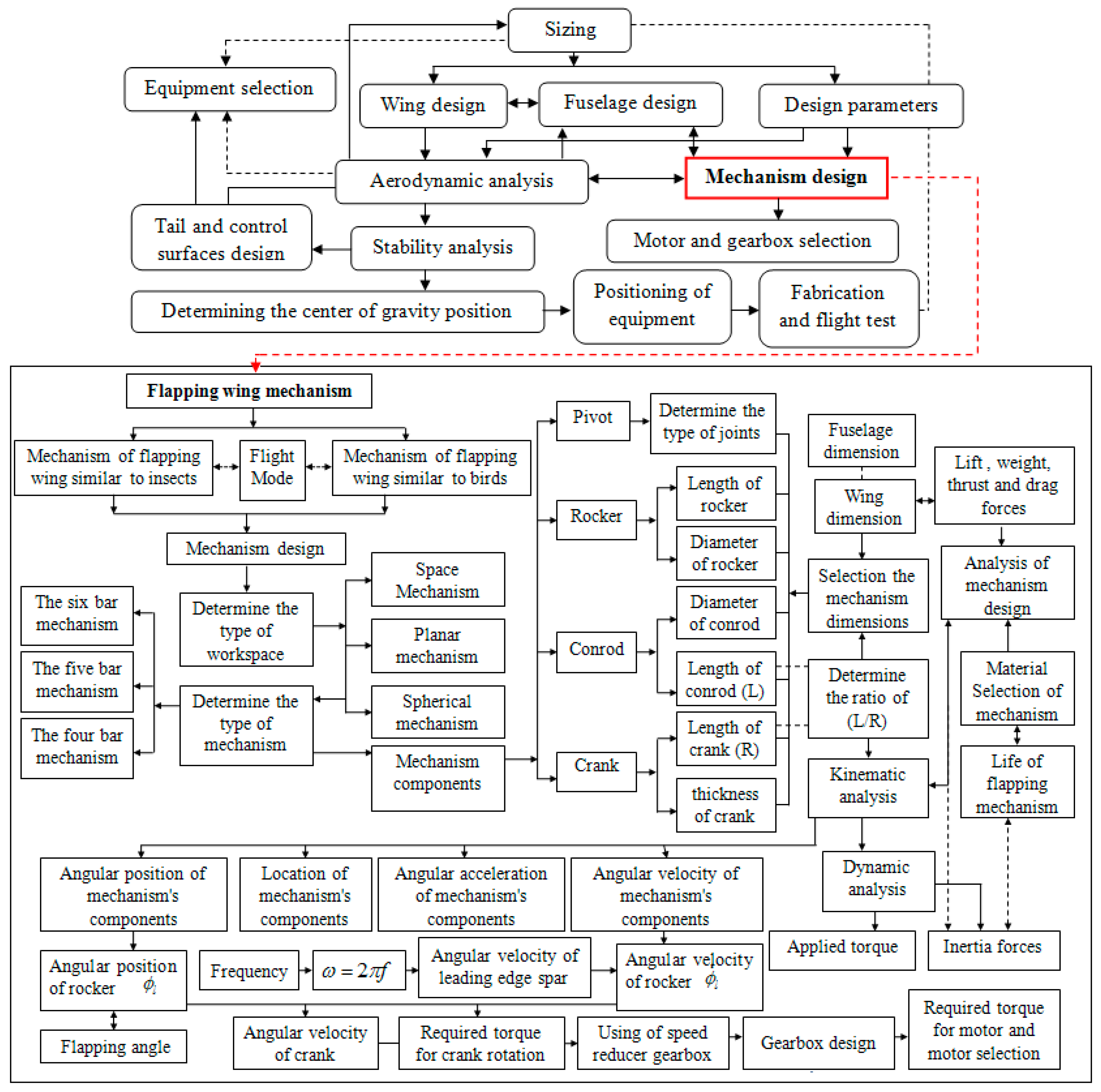
2. Flapping Wing Mechanism Design Process

After performing the sizing process and aerodynamic analysis that led to the determination of the geometry and dimensions of wings and other physical parameters (such as, flapping frequency, upstroke and downstroke flapping angle), as well as the calculation of the aerodynamic forces (such as, the lift, drag, and thrust forces) [4,49,50,51], the actuation mechanism design process is then started. The placement of the actuation mechanism step in flapping wing design process is shown in Figure 2. Issues that need to be considered in the flapping actuation mechanism design, are as follows: (1) the total weight of the actuation mechanism should be as low as possible; (2) the mechanism should be simple, solid, and has few pivots; (3) the flapping motion of the wings should be close to harmonic; (4) the phase difference between the wings should be as close as possible to zero; (5) the wings should be in the same vertical plane; (6) the flapping angles must be equal to the requested amount; (7) the selected shape and dimensions of the actuation mechanism have to avoid the presence of any additional stresses on the wing; and (8) the mechanism components should be able to tolerate the unpredictable forces, such as gust and crash. For each mechanism design, there are an infinite set of dimensions [29]. However, if the dimensions are large, the actuation mechanism will be heavy, and if they are very small, it will be difficult to construct, and it will not be able to tolerate the vibration and stress from the flapping motion.
As mentioned in several references [29,36,41,52], there are various types of actuation mechanisms for flapping wings. The main objective is to convert the rotational motion to flapping motion [53]. Four-bar mechanisms are usually used in mechanism design and according to their arrangements and relative size; a flapping motion can be obtained [29]. It should be noted that the kinematic and performance of a mechanism vary according to their types. Some of the mechanisms have more efficiency and require less torque and create less noise. Therefore, determining the drawbacks and advantages of existing actuation mechanisms can help us to select the best one of them for a well-defined mission. There are two main goals in the selection of the mechanism type which should be taken into consideration. The first one is the selection of a mechanism which needs less torque for flapping motion and consequently selecting a motor with less required power. The second goal is to determine the appropriate range of the transmission angle which is a good indicator for determining the performance of the mechanism, its quality, and its expected noise output [54]. According to Kimbrell [55], the transmission angles should not be lower than 40° and greater than 120° to have a smooth motion. As illustrated in Figure 2, the process of the mechanism design consists of the selection of the mechanism type, selection of the dimensions of each mechanism component, and optimization of the mechanism design by checking different constraints through a parametric study.

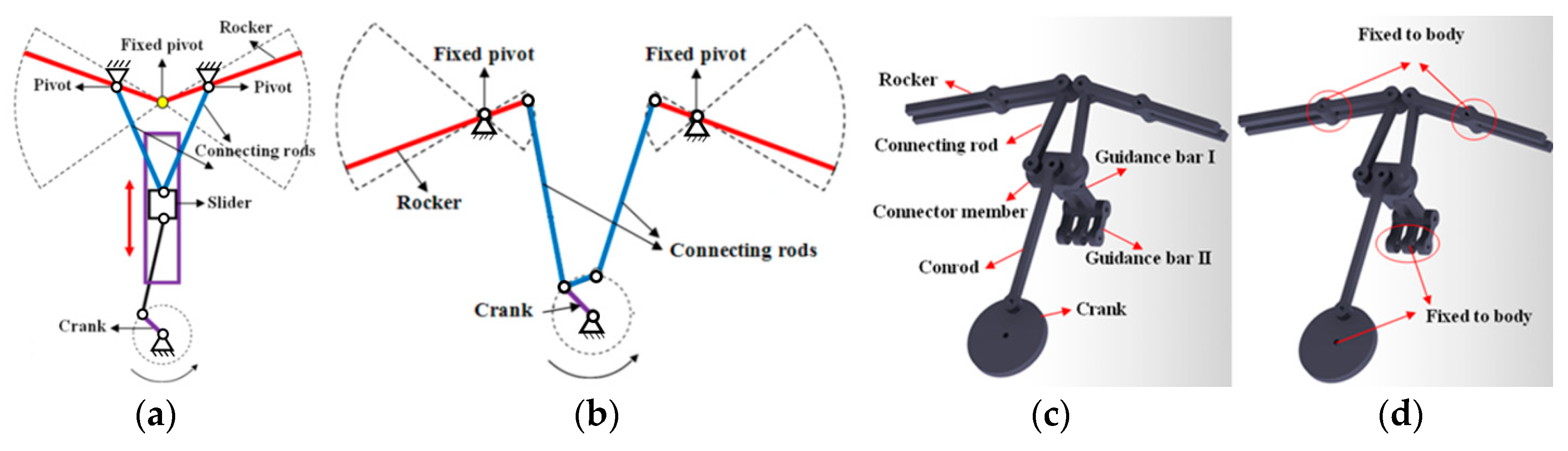
3. Thunder I FWMAV Hybrid Mechanism Design

The novel offered mechanism for the flapping wing is an improved hybrid mechanism with 14 components which has been defined with combination of the slider crank mechanism (Figure 3a) and alternate configuration (Figure 3b) mechanism and its prominent features including its symmetrical shape and motion and all of its connections are hinge. This hybrid actuation mechanism uses two fixed pivots in a similar manner as the alternate configuration and applies the reciprocating motion in a similar manner as the slider crank mechanism. As mentioned in several studies [28,31], in order to increase their symmetrical flapping motion, some flapping wings use sliding systems. However, in this hybrid actuation mechanism, the guidance bars are applied since they have better performance compared to slider systems. In other words, the use of these guidance bars gives the opportunity to eliminate the slider component while its symmetry is preserved. The main task of guidance bars is to provide constraints for the connector member to move in vertical direction. In summary, the main motivation of this novel hybrid actuation mechanism is to increase the flapping efficiency and eliminate the drawbacks of the existed mechanisms. Schematic of the hybrid mechanism and its detailed view are shown in Figure 3c,d.
In the mechanism shown in Figure 3c, the radius of crank is R, the length of the conrod is L, and the connector member is acting as a slider crank mechanism and creates reciprocating motion in a vertical direction. In this mechanism, there is a connecting rod with length b that converts the reciprocating motion created by the connector member to an oscillating motion in the rocker. In this actuation mechanism, the first part of the rocker has a length equal to a. A two dimensional schematic view of the six-bar mechanism is presented in Figure 4a.
In the following sections, the effects of some flapping mechanism components on the kinematic and kinetic parameters are investigated in order to design an efficient actuation mechanism for the fabricated Thunder I FWMAV [4].

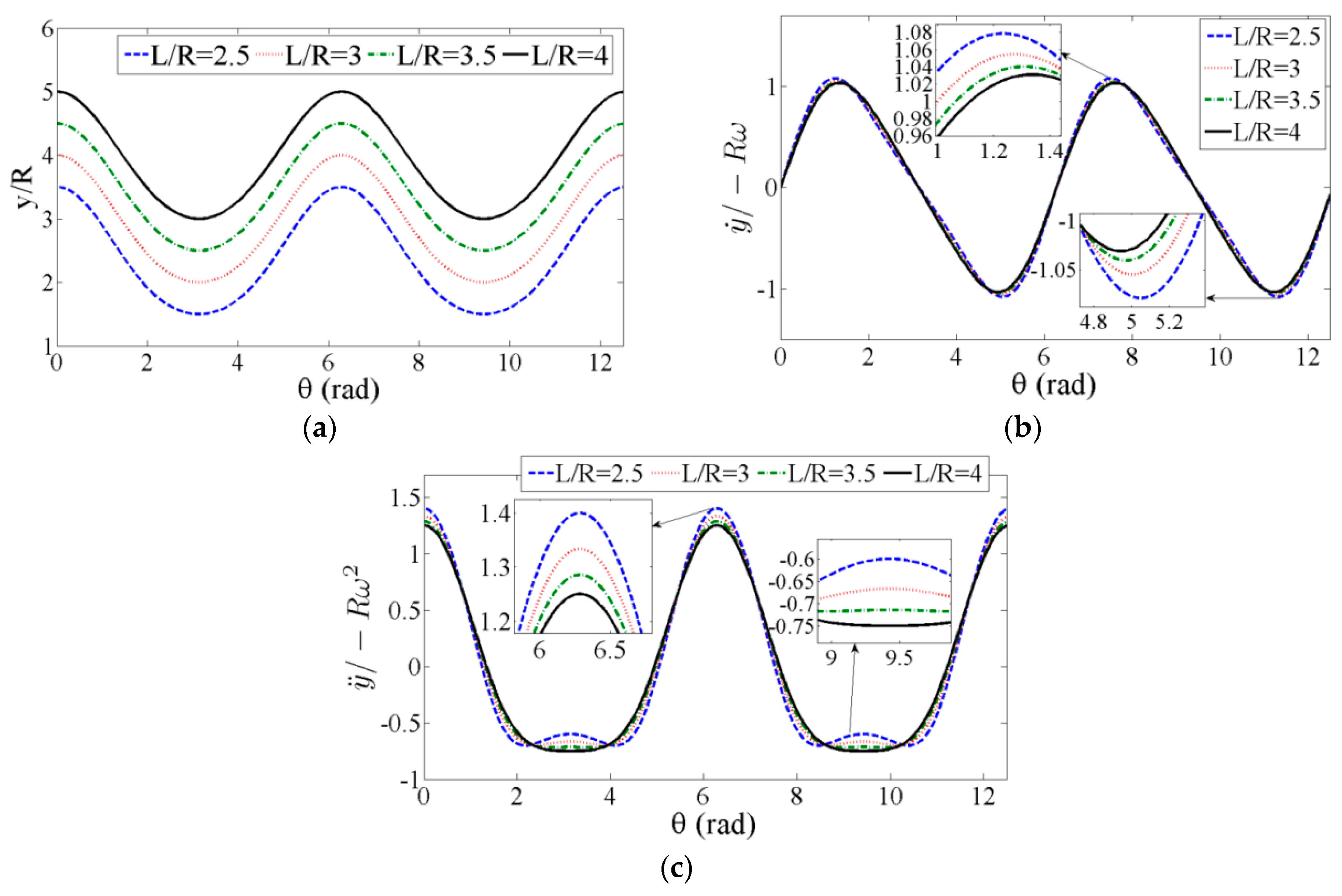
3.1. Determining the Minimum Ratio of L/R

To avoid severe impacts on the mechanism, the motion of the connector member should be harmonic. In order to achieve this goal, the ratio of L/R should be increased for a well-defined value of the radius R of the crank. On the other hand, the increase of this dimensionless parameter results in an increase in the weight and dimensions of the mechanism. Therefore, this parameter should be optimized during the mechanism design process. Considering the schematic presented in Figure 4b, the equations of the position, velocity, and acceleration of the connector member, respectively, are given by:
L 2 R 2 sin 2 θ = ( y R cos θ ) 2 y = R ( ( L / R ) 2 sin 2 θ + cos θ )
y ˙ = R ω ( sin 2 θ 2 ( L / R ) 2 sin 2 θ + sin θ )
y ¨ = R ω 2 ( cos 2 θ ( L / R ) 2 sin 2 θ + sin 2 2 θ 4 ( ( L / R ) 2 sin 2 θ ) 3 2 + cos θ )
In Equations (1)–(3), ω represents the angular velocity of the crank. This angular velocity is related to the frequency of oscillations f by ω = 2πf. In Figure 5a–c, the variations of the non-dimensional position, velocity, and acceleration of the connector membrane as a function of the angular position of the crank are plotted for various values of L/R when the flapping frequency is considered equal to 9 Hz. It follows from these plots that when L/R higher than 3.5, this curve is closer to the harmonic shape. This is particularly obvious in the plotted curves of the dimensionless acceleration, as shown in Figure 5c. Investigating the variations of the dimensionless acceleration as a function of the crank angle, it is found that L/R is equal to 4 is the minimum allowable value in order to get harmonic oscillations. Designing the ratio L/R with higher values than this allowable value, the FWMAV will have higher weight and dimensions.

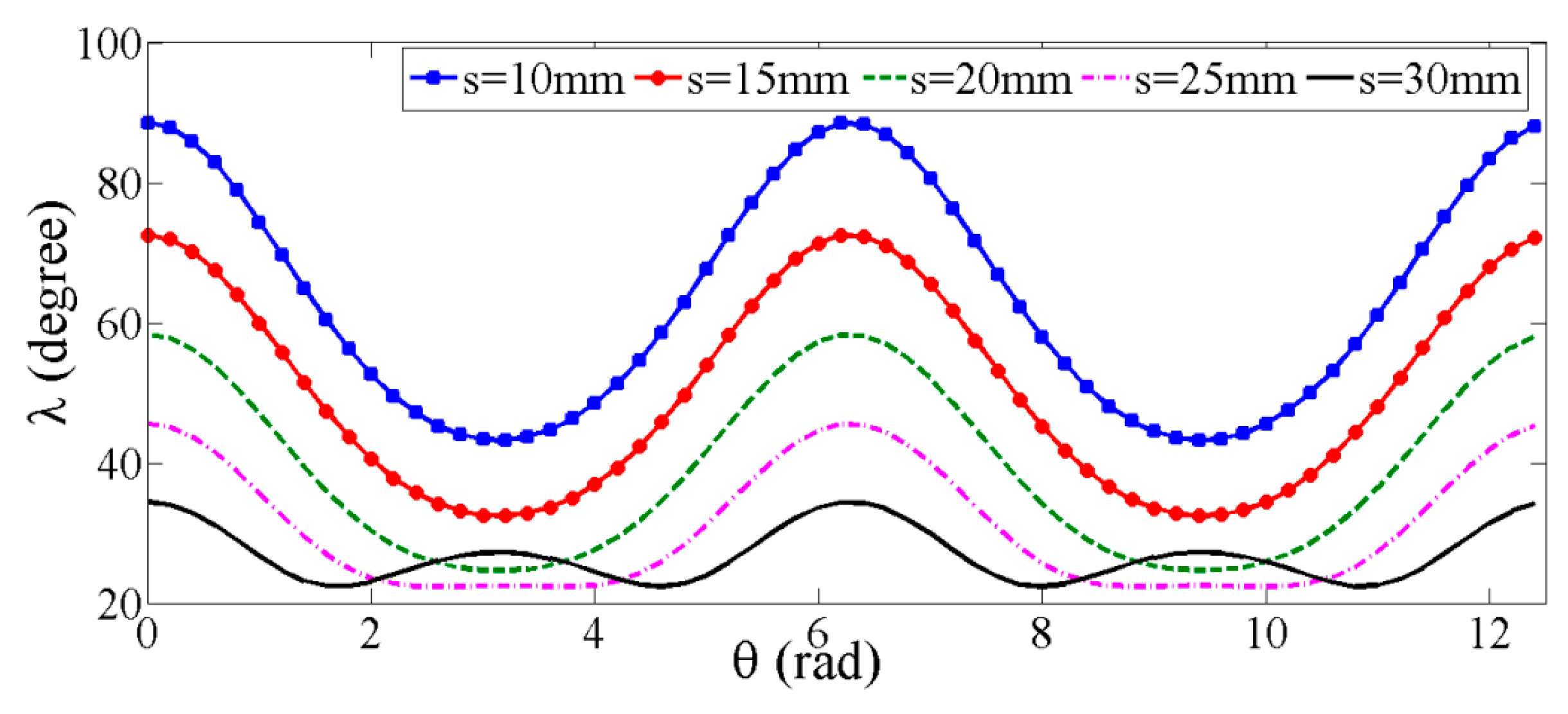
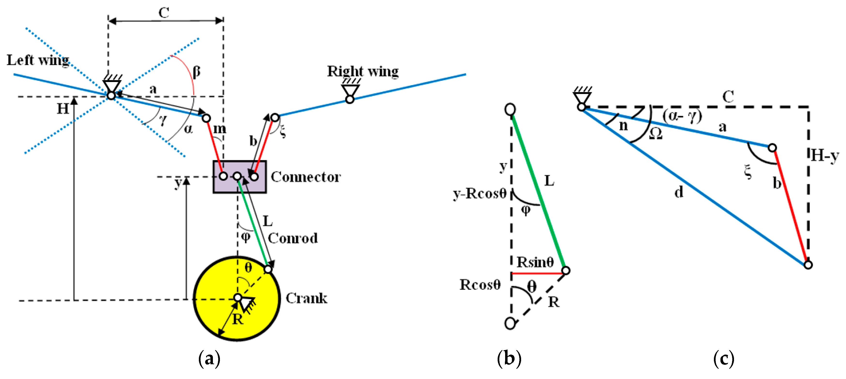
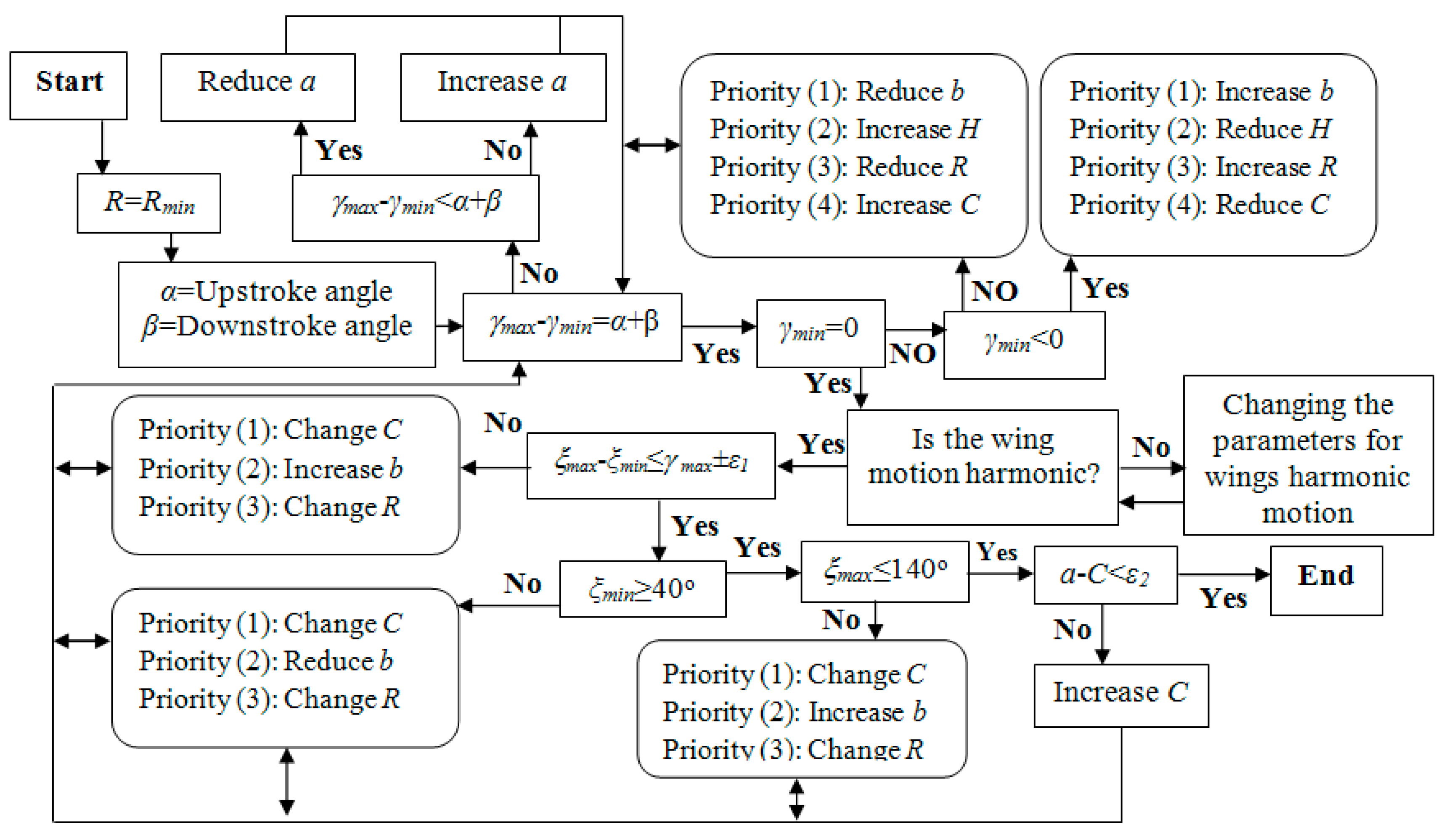
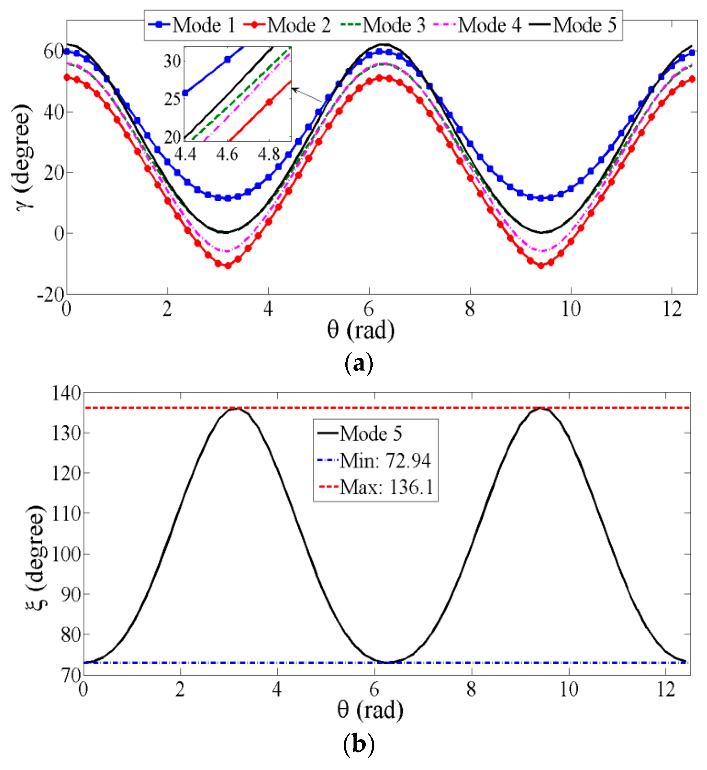
3.2. Determining of the Flapping Angle and the Optimal Angle of Transmission

Next, we determine the relations between the flapping angle (γ), the crank angular position (θ), and other parameters which affect the flapping angle. It follows from Figure 4a that:
H = y + b cos ( m ) + a sin ( α γ )
cos m = 1 ( C a cos ( α γ ) b ) 2
Substituting Equations (1) and (5) into Equation (4), one obtains:
R ( ( L R ) 2 sin 2 θ + cos θ ) + b 1 ( C a cos ( α γ ) b ) 2 + a sin ( α γ ) H = 0
It should be mentioned that H represents the distance between the origin and the point of wing pivot which has a constant length. Therefore, its derivative is zero. Differentiating Equation (6) with time, one obtains:
γ ˙ = ω ( R ( sin 2 θ 2 ( L / R ) 2 sin 2 θ + sin θ ) a ( C a cos ( α γ ) ) sin ( α γ ) b 1 ( C a cos ( α γ ) b ) 2 a cos ( α γ ) )
γ ¨ = γ ˙ γ × γ ˙ + γ ˙ θ × θ ˙
Equations (7) and (8) show the expressions of the angular velocity and acceleration of the FWMAV, respectively. In Equation (8), θ ˙ = ω denotes the angular velocity of the crank and has a constant value. According to Figure 4c, we have:
Ω = tan 1 H y C = tan 1 ( H R ( c 2 sin 2 θ + cos θ ) C )
Using the law of sines, the angle n can be expressed as:
sin n b = sin ξ d n = sin 1 ( b sin ξ d )
In Equations (9) and (10), c = L/R and d can be calculated using one of these relations:
d = a 2 + b 2 2 a b cos ξ
d = C 2 + ( H y ) 2 = C 2 + [ H R ( ( c ) 2 sin 2 θ + cos θ ) ] 2
According to Equations (11) and (12), the transmission angle (ξ) can be expressed as:
ξ = cos 1 ( [ H R ( ( c ) 2 sin 2 θ + cos θ ) ] 2 + C 2 a 2 b 2 2 a b )
It follows from Figure 4c, that:
( α γ ) = Ω n = tan 1 ( H R ( c 2 sin 2 θ + cos θ ) C ) sin 1 ( b sin ξ d )
Hence, the flapping angle γ is given by:
γ = ( tan 1 ( H R ( c 2 sin 2 θ + cos θ ) C ) sin 1 ( b sin ( cos 1 ( [ H R ( ( c ) 2 sin 2 θ + cos θ ) ] 2 + C 2 a 2 b 2 2 a b ) ) C 2 + [ H R ( ( c ) 2 sin 2 θ + cos θ ) ] 2 ) ) + α
For a better conversion of the power from motor to the wings, it was shown by Mabie and Reinholtz [56] that the transmission angle ξ should be approximately equal to 90 degrees. This means that the rocker and the connecting rod are perpendicular to each other. Inspecting Equation (13), it is clear that the values of a, b, H, R, and L/R are so important to determine the optimum value of the transmission angle ξ Furthermore, it follows from Equations (13) and (14) that the effective parameters affecting the flapping and transmission angles are common. Thus, these two angles should be determined simultaneously. To this end, we propose a methodology to identify the optimum value for the flapping and transmission angles, as presented in Figure 6.
In this methodology, the design is started with considering initial values for L/R, R, a, b, H, and C, and then based on the shown flowchart in Figure 6 and the required values of the upstroke and downstroke flapping angles, the optimized value of each parameter can be obtained. As presented in the flowchart, the methodology considers a minimum value for the crank radius R. This parameter has a great impact on the other mechanism components. The increase of this parameter value increases the weight and dimensions of the mechanism. It should be noted that a reduction of the crank radius can also cause limitations in mechanical engineering design of the mechanism. In this process, the upstroke (α) and downstroke (β) angles are two known parameters which are considered as constraints based on the sizing design [4]. The difference between the maximum and minimum flapping angles (γmaxγmin) generated by the actuation mechanism is one of the constraint that determines the optimum value of a. If the value of (γmaxγmin) is less than the sum of the upstroke and downstroke angles (α + β), the value of a should be reduced and if is more than (α + β), the value of a should be increased. After determining the optimum value of a which satisfy the flapping angle condition (γmaxγmin = α + β), the next condition (γmin = 0) is investigated. If the γmin > 0 or γmin < 0, according to defined priorities in flowchart shown in Figure 6, the value of b, H, R, or C are revised to get γmin = 0. After these steps, the harmonic motion of wing is tested. If the motion is harmonic, next step is started. Otherwise, the selected values of the parameters should be changed.
As mentioned above, the optimum value of the transmission angle is 90°. Since the angle will be constantly changing during the motion cycle of the actuation mechanism, there is a position at which the transmission angle will deviate most from 90°. In practice [56,57], it was stated that if the maximum deviation of the transmission angle from 90° exceeds 50°, the mechanism will be locked [57], therefore the maximum and minimum values of the transmission angle ξ are respectively, considered equal to 40° and 140°. It was also reported that the difference between the maximum and minimum values of the transmission angle (ξmax − ξmin) should be almost equal to the maximum flapping angle (γmax = α + β) [54]. As shown in Figure 6, if the mentioned conditions are not satisfied, some modifications are needed according to the defined priorities. After satisfying all of these conditions, to avoid the left and right wings crossing each other, the difference between the value of a and C should be as low as possible (aC < ε).
Considering the values of the upstroke (α) and downstroke (β) angles as well as the flapping frequency (f) are equal to 32 degrees, 30 degrees, and 9 Hz, respectively, and performing reciprocating calculations based on the proposed methodology, the first dimensions (mode (1)) of the designed six-bar actuation mechanism are obtained. It should be noted that after doing reciprocating calculations and according to what was discussed for the determination of the minimum length of R, the optimum value of R is selected to be equal to 8 mm which can provide the harmonic motion for the wings. The five final scenarios (modes (1–5)) for optimizing the mechanism dimensions based on the offered methodology are presented in Table 2. As seen in mode (1), the first defined condition (γmaxγmin = α + β) is not accomplished. Therefore, the dimensions of a and b should be reduced to get this condition (γmaxγmin = α + β = 62°) in mode (2). Inspecting the obtained values in mode (2), it is clear that γmin < 0 and according to flowchart the dimension of b should be increased which gives the mode (3). After doing these reciprocating calculations, mode (5) is determined which satisfies all of the required conditions.
The plotted curves in Figure 7a show the variations of the flapping angle (γ) as a function of the crank angle (θ) for the five considered modes during the design process. Clearly, the oscillations of the flapping angle are harmonic for all modes. The minimum value of the flapping angle for both modes (3) and (5) is zero. However, their associated maximum values are, respectively, equal to 55.6° and 62°. The later one is equal to α + β, as required in the design process. Considering mode (5) where (γmax − γmin = α + β) and γmin = 0, we plot in Figure 7b the variation of the transmission angle as a function of the crank angle. It follows from this plot that the motion of this angle is harmonic with maximum and minimum values, respectively, equal to 136.1° < 140° and 72.94° > 40° and ξmax − ξmin = 63.15° ≈ γmax.

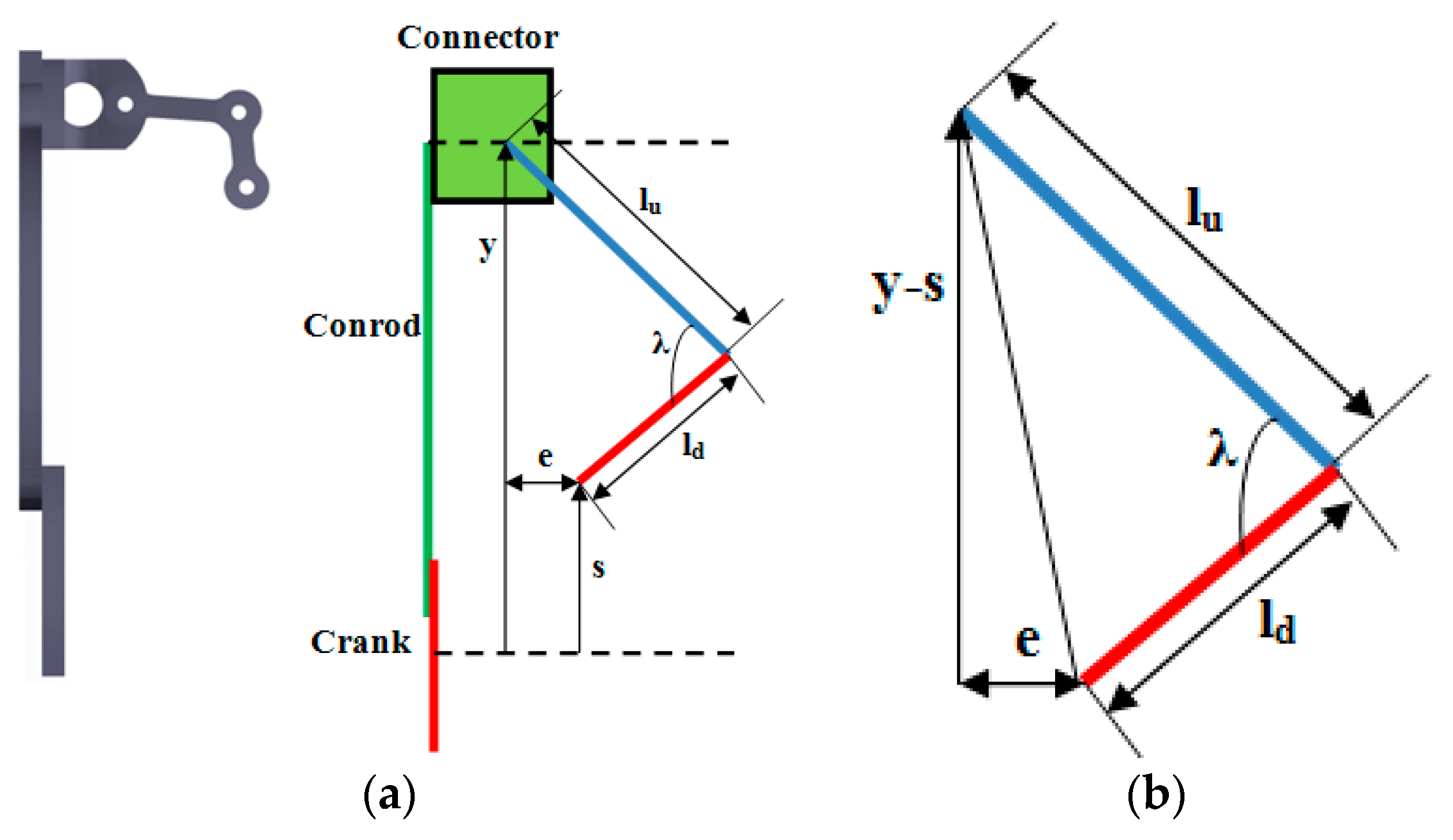
3.3. Designing of the Guidance Bars

The second part of the flapping wing mechanism consists of the guidance bars and the connector member. As shown in Figure 8a, λ denotes the angle between the top and bottom guidance bars. The lengths of these bars are, respectively, represented by lu and ld and considered equal to 25 mm and 20 mm.
According to the triangle shown in Figure 8b, we have:
( y s ) 2 + e 2 = l u 2 + l d 2 2 l u l d cos λ
Substituting y by its expression given in Equation (1), the angle λ can be expressed as:
λ = cos 1 ( ( R ( ( c ) 2 sin 2 θ + cos θ ) s ) 2 + e 2 l u 2 l d 2 2 l u l d )
It follows from Equation (17) that for adjusting the λ angle, the parameters e and s are needed. These parameters determine the position of the bottom guidance bar relative to the reference. Setting the value of e to be equal to 10 mm, the distance s from the reference to the bottom guidance bar is determined in such a way the motion of the angle λ is harmonic. It should be mentioned that this distance should be maximized to reduce the needed size during oscillation. Figure 9 shows the variation of λ as a function of the crank angle for different values of s. It is clear that the maximum possible value of s to guarantee harmonic oscillation is 15 mm.
The final design parameters for the guidance bars are given in Table 3.

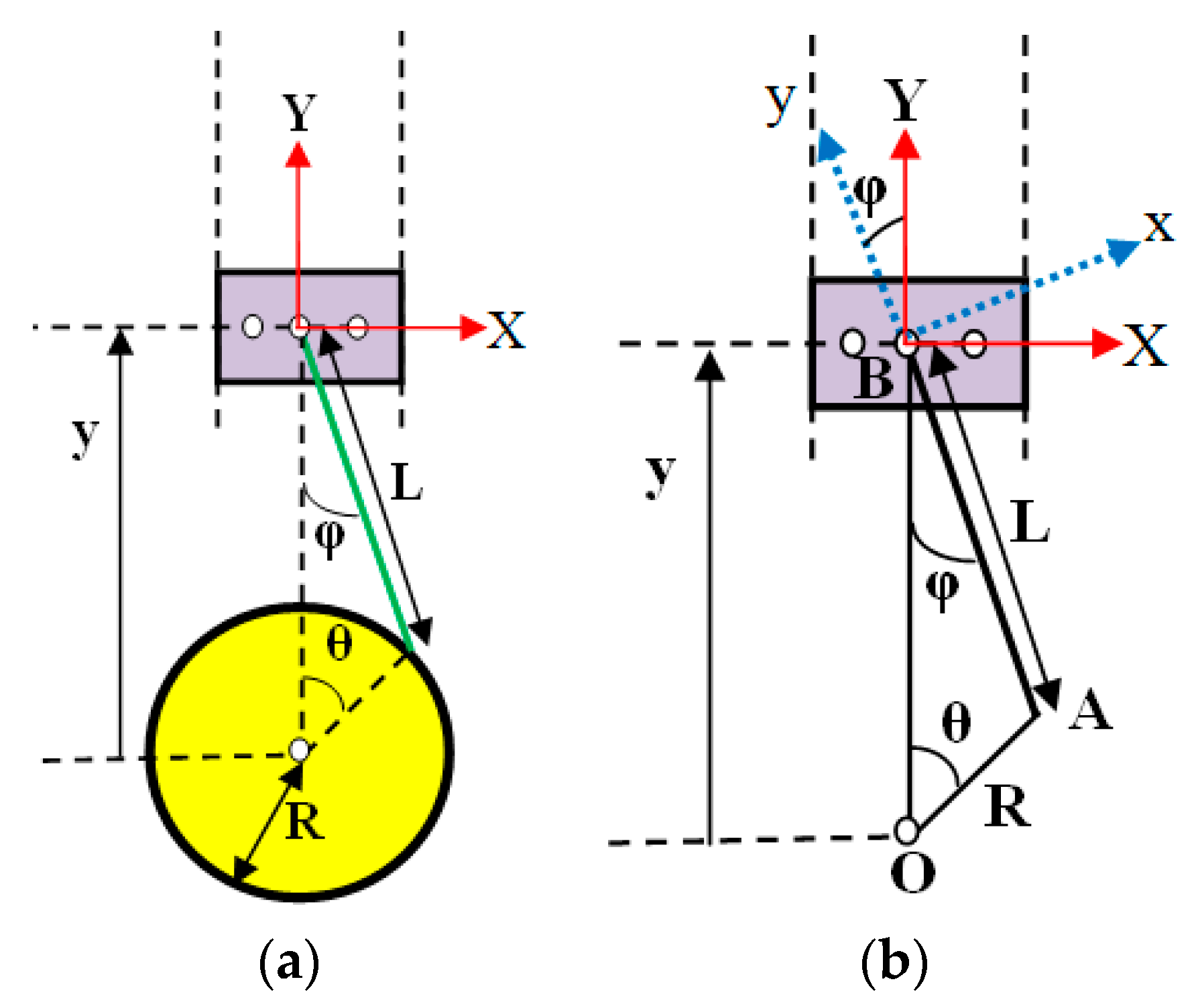
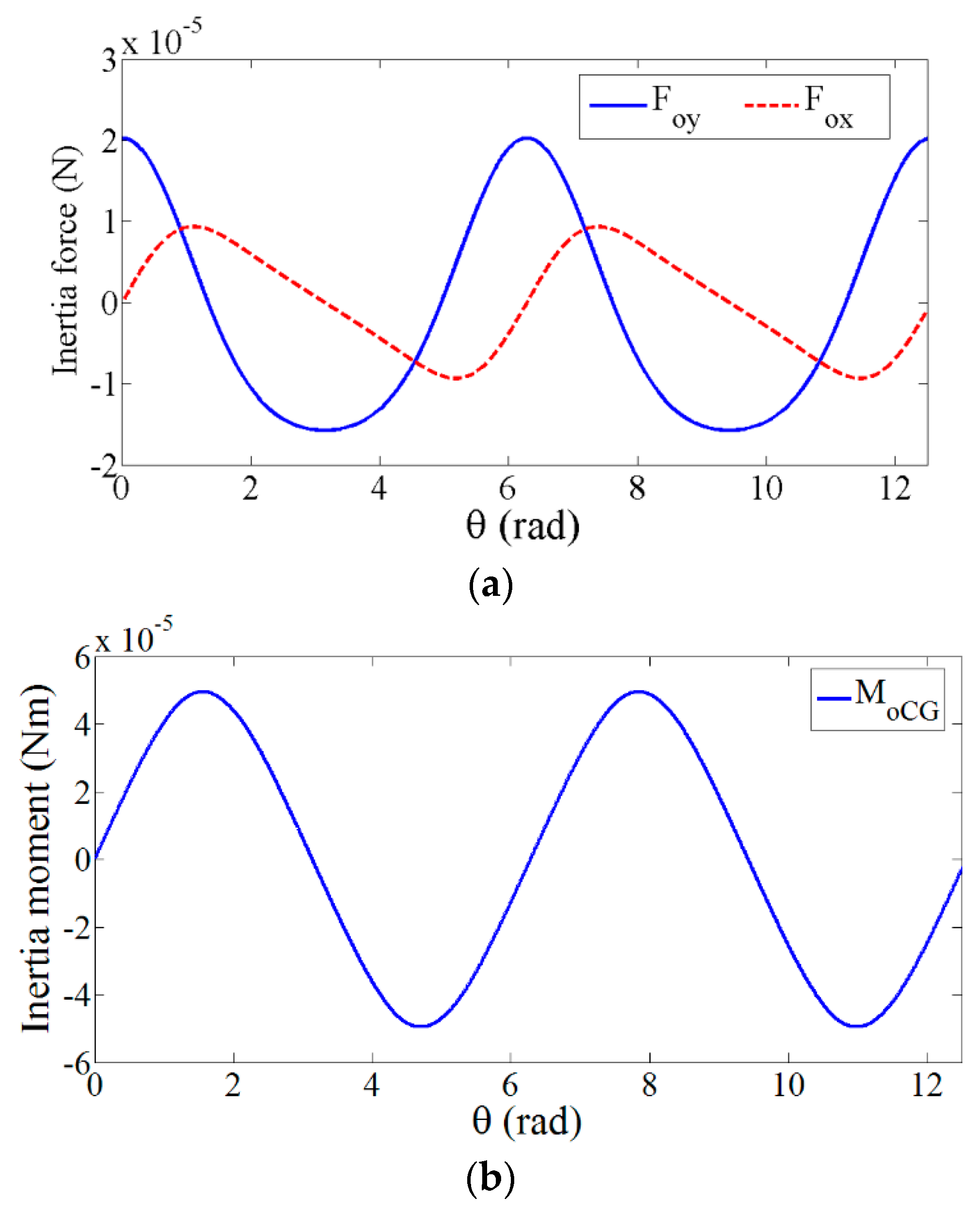
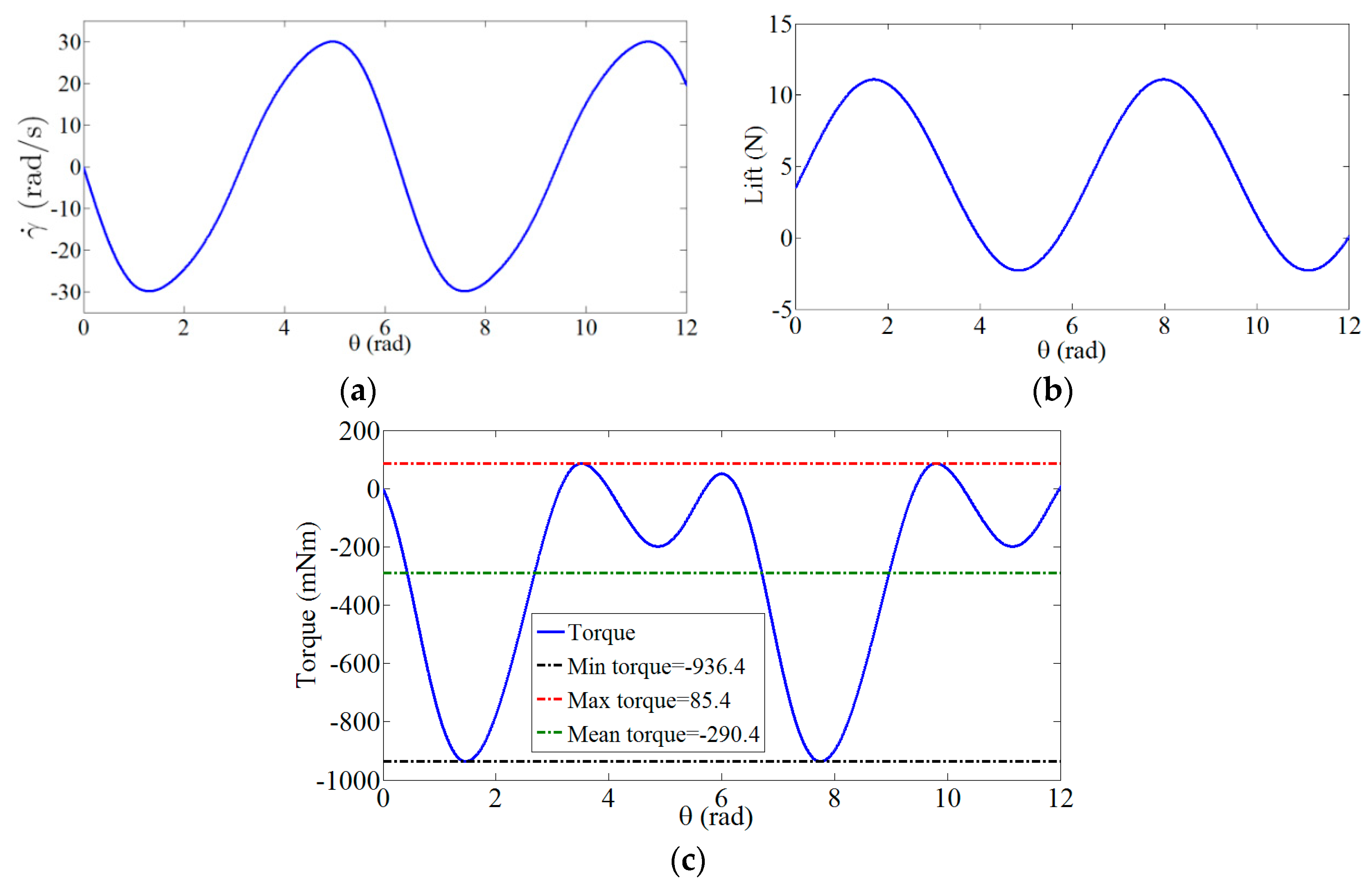
3.4. Dynamic Analysis of the Designed Actuation Mechanism

After determining the dimensions of the actuation mechanism, a dynamic analysis was performed to investigate the effects of the inertia forces and moments on the structure of the mechanism starting from the given schematics in Figure 10a,b.
The connector member can only move in the Y direction and thus can be assumed as a slider. To determine the inertia force and moment of the conrod, a new coordinate system was considered, as shown in Figure 10b. The new coordinate system is related to the original coordinate system by:
{ i = cos φ I + sin φ J j = cos φ J sin φ I { I = cos φ i sin φ j J = sin φ i + cos φ j
To calculate the acceleration at the center of mass of the conrod, the accelerations of points A and B should be calculated. The magnitude of the acceleration at point A and its vectorial representation are, respectively, given by:
A A = R ω 2
A A = R ω 2 ( sin θ I + cos θ J )
If the acceleration equations are written in x-y coordinate system, one obtains:
{ a A x = R ω 2 ( sin θ cos φ + cos θ sin φ ) = R ω 2 sin ( θ + φ ) a A y = R ω 2 ( cos θ cos φ sin θ sin φ ) = R ω 2 cos ( θ + φ )
The acceleration of conrod at point B is given by:
A B = A B X I + A B Y J A B = A B Y J = Y ¨ J
From Figure 10b, Y can be expressed as:
Y = R cos θ + L cos φ Y ˙ = R ω sin θ L φ ˙ sin φ
Considering the following relationship between the angles θ and φ:
sin φ R = sin θ L φ = sin 1 ( R L θ )
thus:
A B Y = R ω 2 ( cos θ + cos 2 θ ( L / R ) 2 sin 2 θ + sin 2 2 θ 4 ( ( ( L / R ) 2 sin 2 θ ) 3 ) )
The acceleration of the conrod at point B in the x-y coordinate system can be written as:
a B x i + a B y j = R ω 2 ( cos θ + cos 2 θ ( L / R ) 2 sin 2 θ + sin 2 2 θ 4 ( ( ( L / R ) 2 sin 2 θ ) 3 ) ) ( sin φ i + cos φ j )
Applying the relative acceleration equations, the acceleration of the center of mass of the conrod can be calculated using one of these expressions:
a C G = a A + α c o n × ( L 2 j ) + ω c o n × ( ω c o n × L 2 j )
a C G = a B + α c o n × ( L 2 j ) + ω c o n × ( ω c o n × ( L 2 j ) )
Summing Equations (27) and (28), the following relations are obtained:
2 a C G = a A + a B a C G = a A + a B 2
a C G = a C G x i + a C G y j = a A x + a B x 2 i + a A y + a B y 2 j
After substituting Equations (21) and (26) into Equations (29) and (30), one obtains:
a C G x = 0.5 [ R ω 2 sin ( θ + φ ) + R ω 2 sin φ × ( cos θ + cos 2 θ ( L / R ) 2 sin 2 θ + sin 2 2 θ 4 ( ( ( L / R ) 2 sin 2 θ ) 3 ) ) ]
a C G y = 0.5 [ R ω 2 cos ( θ + φ ) + R ω 2 cos φ × ( cos θ + cos 2 θ ( L / R ) 2 sin 2 θ + sin 2 2 θ 4 ( ( ( L / R ) 2 sin 2 θ ) 3 ) ) ]
The angular acceleration of the conrod can be calculated as:
α c o n = φ ¨ = R ω 2 sin θ L 2 R 2 sin 2 θ + R 3 ω 2 sin θ cos 2 θ ( L 2 R 2 sin 2 θ ) 3
To calculate the inertia force and moment generated by the conrod, the mass (m) and moment of inertia (I) of the conrod are determined which are equal to 0.70 g and 6 × 10⁻⁸ kg·m2, respectively. Consequently, the inertia forces and moment can be expressed as:
F O x = m a C G x , F O y = m a C G y , M O C G = I φ ¨
In Figure 11a,b, the variations of the inertia forces and moment as a function of the crank angle are plotted. Inspecting these plots, it is clear that these inertia forces and moment have a negligible effect on the performance of the system. In fact, the magnitude of the force is very small compared to the aerodynamic lift of the flapping wing MAV which is determined to be equal to 3.4 N [4].

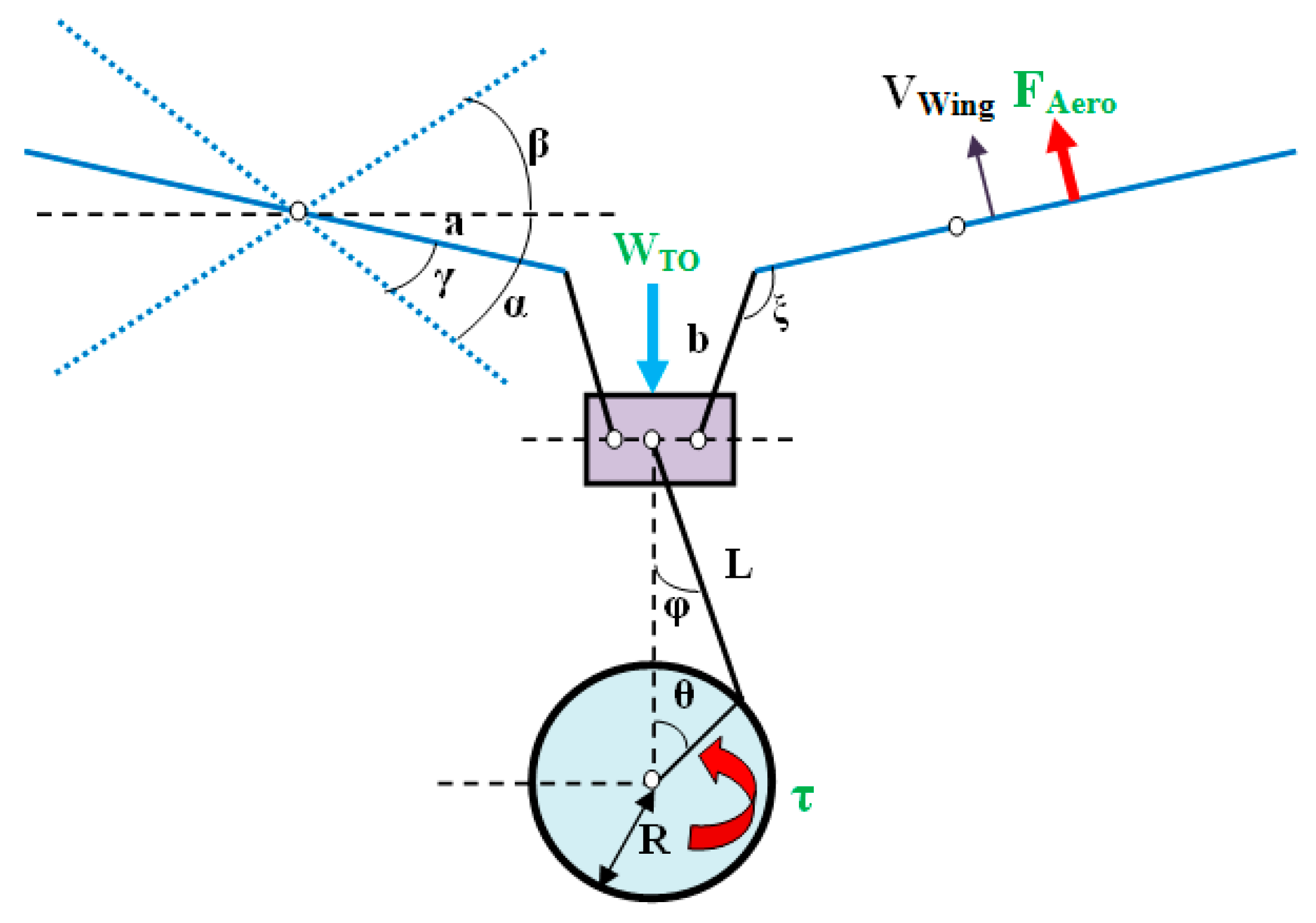
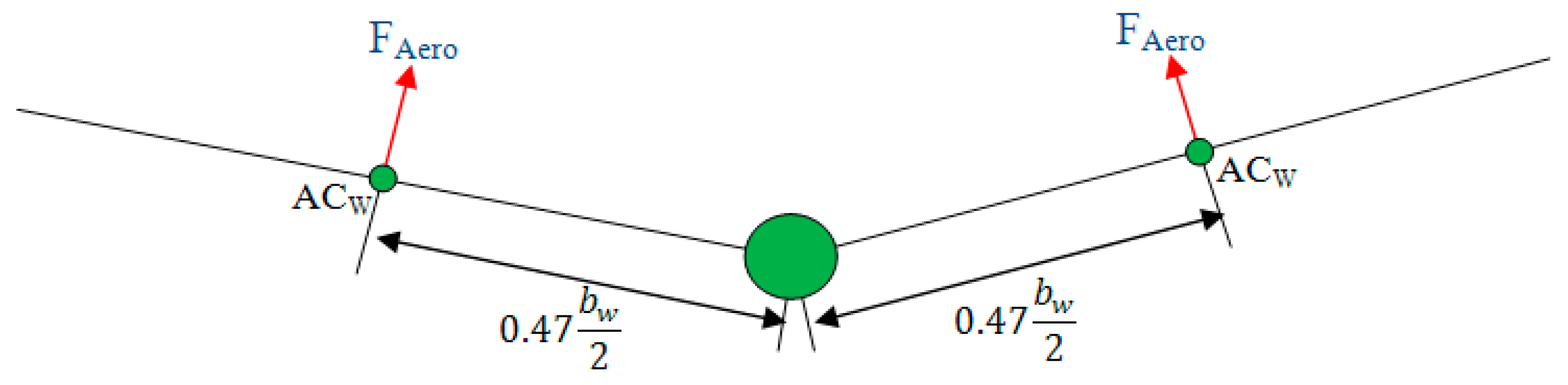
3.5. Required Torque and Power

In this section, the required torque for the crank is determined in order to give the exact lift force for the flapping wing. A schematic including different applied forces on the actuation mechanism is presented in Figure 12.
To solve the kinematic of the mechanism shown in Figure 12 and calculate the required torque for the crank rotation, the external forces should be determined. In flapping mechanism analysis, the external forces are aerodynamic forces acting on wing and the input torque acting on the crank. The relationship between the needed torque and the aerodynamic force is given by [54,55]:
τ C r a n k = 2 F A e r o . V F θ ˙
In Equation (36), V F is linear velocity of the wing and F A e r o is the lift force which is generated by semi wing. In Figure 13 the position of the aerodynamic forces on every semi wing are presented.
According to Figure 13 and considering the position of the aerodynamic center to the central point which is equal to 0.47·(0.5bw) [58] where bw is the wingspan, the linear velocity of the wing is expressed as:
V F = 0.47 b w 2 γ ˙
It should be noted that the only aerodynamic forces which are exerted on the wing in vertical direction, in cruise flight of flapping wing, is the lift force which is approximated by this function [4]:
L w 6.6855 cos ( 18 π t 0.5454 π ) + 4.3845
Substituting Equation (36) into Equation (35), one obtains:
τ C r a n k = 0.47 F A e r o b w γ ˙ θ ˙ = 0.47 L w b w γ ˙ 2 θ ˙
In Equation (37), the time can be expressed as a function of the crank angle as:
{ ω = 2 π f θ = ω t t = θ 2 π f
In Figure 14a–c, we plot the variations of the wing angular velocity, lift, and required torque as a function of the crank angle, respectively. From Figure 14c, the minimum, maximum, and mean values of the required torque are determined.
According to Figure 14b, the required mean and maximum power values for the crank rotation are given by:
P ¯ = T M e a n ω = 0.290 × 56.55 = 16.4 W
P M a x = T M a x ω = 0.9364 × 56.55 = 53 W

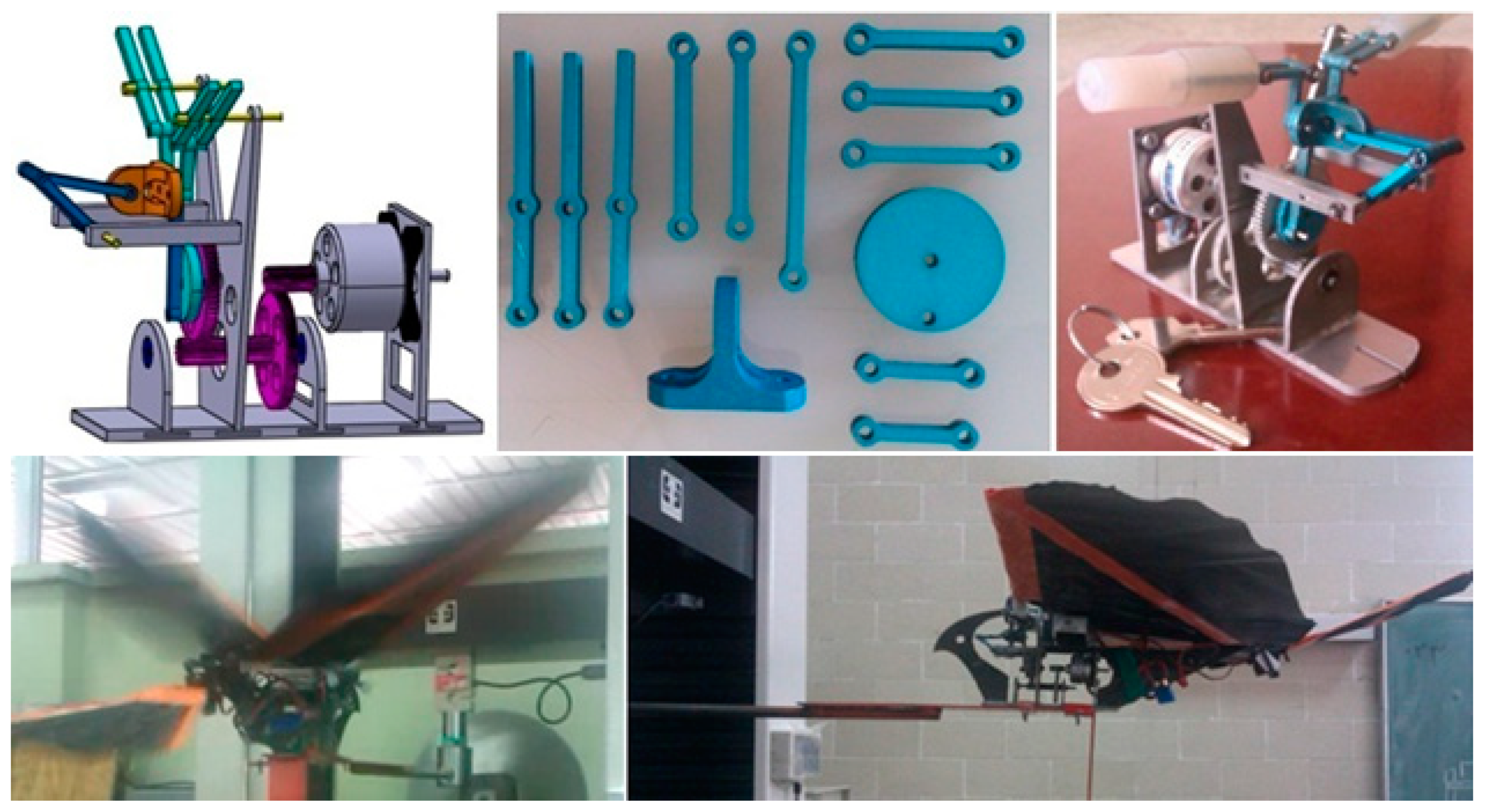
4. Fabrication and Experimental Testing of the Hybrid Actuation Mechanism

After determining the optimum dimensions of the actuation mechanism, as well as the required torque and power to rotate the crank, the fabrication step is started. According to the shape of the mechanism, it was necessary that a container was designed in order to hold the actuation mechanism of the flapping wing. After doing accurate and different analyses, the mechanism is simulated and manufactured [4]. To fabricate this actuation mechanism, the aluminum was used as the principal material. It should be mentioned that the mechanism components including gears and holder frame were manufactured with wire cut machine. For surface treatment of the mechanism, all its components were anodized. After designing and fabricating the Thunder I mechanism, various tests were then performed [4]. The first test was carried out to check the flapping frequency, while the second one was to check the upstroke and downstroke angles, and both of these tests were successful. More results can be found in [4]. In Figure 15, the components of the actuation mechanism, its final design, and experimental test of Thunder I FWMAV are shown.

5. Conclusions

To design an efficient actuation mechanism for a flapping wing micro air vehicle named “Thunder I”, various kinematic and kinetic analyses have been performed. After performing these analyses, a methodology that relates the optimum parameters of the actuation mechanism to the entrance parameters, such as the upstroke and downstroke angles and flapping frequency was developed. Using this methodology, it was shown that an efficient hybrid actuation mechanism can be designed with having symmetrical flapping motion and hinge connections for all components. This designed mechanism for Thunder I which consisted of fourteen components consisting of two six-bar mechanisms was then manufactured and tested.

Author Contributions

Writing—original draft, M.H.; Writing—review & editing A.A.

Funding

This research received no external funding.

Conflicts of Interest

The authors declare no conflict of interest.

References

  1. Wood, R.J.; Finio, B.; Karpelson, M.; Ma, K.; Pérez-Arancibia, N.O.; Sreetharan, P.S.; Tanaka, H.; Whitney, J.P. Progress on ‘pico’ air vehicles. Int. J. Robot. Res. 2012, 31, 1292–1302. [Google Scholar] [CrossRef]
  2. Hassanalian, M.; Throneberry, G.; Abdelkefi, A. Investigation on the planform and kinematic optimization of bio-inspired nano air vehicles for hovering applications. Meccanica 2018, 53, 2273–2286. [Google Scholar] [CrossRef]
  3. Lin, C.S.; Hwu, C.; Young, W.B. The thrust and lift of an ornithopter’s membrane wings with simple flapping motion. Aerosp. Sci. Technol. 2006, 10, 111–119. [Google Scholar] [CrossRef]
  4. Hassanalian, M.; Abdelkefi, A.; Wei, M.; Ziaei-Rad, S. A novel methodology for wing sizing of bio-inspired flapping wing micro air vehicles: Theory and prototype. Acta Mech. 2016. [Google Scholar] [CrossRef]
  5. Hassanalian, M.; Throneberry, G.; Abdelkefi, A. Wing shape and dynamic twist design of bio-inspired nano air vehicles for forward flight purposes. Aerosp. Sci. Technol. 2017, 68, 518–529. [Google Scholar] [CrossRef]
  6. Guo, S.; Li, D.; Wu, J. Theoretical and experimental study of a piezoelectric flapping wing rotor for micro aerial vehicle. Aerosp. Sci. Technol. 2012, 23, 429–438. [Google Scholar] [CrossRef]
  7. Hassanalian, M.; Abdelkefi, A. Classifications, applications, and design challenges of drones: A review. Prog. Aerosp. Sci. 2017, 91, 99–131. [Google Scholar] [CrossRef]
  8. Tsai, B.J.; Fu, Y.C. Design and aerodynamic analysis of a flapping-wing micro aerial vehicle. Aerosp. Sci. Technol. 2009, 13, 383–392. [Google Scholar] [CrossRef]
  9. Abdullah, E.J.; Majid, D.L.; Romli, F.I.; Gaikwad, P.S.; Yuan, L.G.; Harun, N.F. Active control of strain in a composite plate using shape memory alloy actuators. Int. J. Mech. Mater. Des. 2015, 11, 25–39. [Google Scholar] [CrossRef]
  10. Mateti, K. Flapping Wing Mechanisms for Pico Air Vehicle Using Piezoelectric Actuators. Ph.D. Thesis, The Pennsylvania State University, State College, PA, USA, May 2012. [Google Scholar]
  11. Sabri, F.; Meguid, S.A. Flutter boundary prediction of an adaptive morphing wing for unmanned aerial vehicle. Int. J. Mech. Mater. Des. 2011, 7, 307. [Google Scholar] [CrossRef]
  12. Bruggerman, B. Improving Flight Performance of DelFly II in Hover by Improving Wing Design and Driving Mechanism. Master’s Thesis, Delft University of Technology, Delft, The Netherlands, 2010. [Google Scholar]
  13. Chand, A.N.; Kawanishi, M.; Narikiyo, T. Design analysis, modeling and experimental validation of a bird-like flapping-wing flying robot. In Proceedings of the IMAV 2014 International Micro Air Vehicle Conference and Competition 2014, Delft, The Netherlands, 12–15 August 2014. [Google Scholar]
  14. Sean Kinkade Ornithopter. U.S. Patent 9,858,922, 17 May 2001.
  15. Tandon, A.; Vajpai, A.; Mishra, A.N. Design of an autonomous ornithopter with live video reception for military surveillance. Int. J. Res. Eng. Technol. 2013, 2, 489–493. [Google Scholar]
  16. Ghommem, M.; Hassanalian, M.; Al-Marzooqi, M.; Throneberry, G.; Abdelkefi, A. Sizing process, aerodynamic analysis, and experimental assessment of a biplane flapping wing nano air vehicle. Proceedings of the Institution of Mechanical Engineers, Part G: Journal of Aerospace Engineering, 2009; 0954410019852570. [Google Scholar]
  17. Keennon, M.; Klingebiel, K.; Won, H.; Andriukov, A. Tailless Flapping Wing Propulsion and Control Development for the Nano Hummingbird Micro Air Vehicle. In Proceedings of the American Helicopter Society Future Vertical Lift Aircraft Design Conference, San Francisco, CA, USA, 18–20 January 2012. [Google Scholar]
  18. Keennon, M.T.; Klingebiel, K.R.; Won, H.; Andriukov, A. Development of the nano hummingbird: A tailless flapping wing micro air vehicle. In Proceedings of the 50th AIAA Aerospace Sciences Meeting including the New Horizons Forum and Aerospace Exposition, Nashville, TN, USA, 9–12 January 2012. [Google Scholar]
  19. Nano Hummingbird. Available online: http://www.avinc.com/nano (accessed on 29 February 2012).
  20. Nguyen, Q.V.; Chan, W.L.; Debiasi, M. Hybrid design and performance tests of a hovering insect-inspired flapping-wing micro aerial vehicle. J. Bionic Eng. 2016, 13, 235–248. [Google Scholar] [CrossRef]
  21. Roshanbin, A.; Altartouri, H.; Karasek, M.; Preumont, A. COLIBRI: A hovering flapping twin-wing robot. Int. J. Micro Air Veh. 2017, 9, 270–282. [Google Scholar] [CrossRef]
  22. Ma, K.Y.; Chirarattananon, P.; Fuller, S.B.; Wood, R.J. Controlled flight of a biologically inspired, insect-scale robot. Science 2013, 340, 603–607. [Google Scholar] [CrossRef]
  23. Leal, P.B.; Savi, M.A. Shape memory alloy-based mechanism for aeronautical application: Theory, optimization and experiment. Aerosp. Sci. Technol. 2018, 76, 155–163. [Google Scholar] [CrossRef]
  24. Fenelon, M.A.A.; Furukawa, T. Design of an active flapping wing mechanism and a micro aerial vehicle using a rotary actuator. Mech. Mach. Theory 2010, 45, 137–146. [Google Scholar] [CrossRef]
  25. Madangopal, R.; Khan, Z.A.; Agrawal, S.K. Biologically inspired design of small flapping wing air vehicles using four-bar mechanisms and quasi-steady aerodynamics. J. Mech. Des. 2005, 127, 809–816. [Google Scholar] [CrossRef]
  26. Cox, A.; Monopoli, D.; Cveticanin, D.; Goldfarb, M.; Garcia, E. The development of elastodynamic components for piezoelectrically actuated flapping micro-air vehicles. J. Intell. Mater. Syst. Struct. 2002, 13, 611–615. [Google Scholar] [CrossRef]
  27. Karpelson, M.; Wei, G.Y.; Wood, R.J. A review of actuation and power electronics options for flapping wing robotic insects. In Proceedings of the IEEE International Conference on Robotics and Automation, Pasadena, CA, USA, 19–23 May 2008. [Google Scholar]
  28. Benedict, M.; Sudhakar, K.; Issac, K.K. Aeroelastic Design and Manufacture of an Efficient Ornithopter Wing; Department of Aerospace Engineering, Indian Institute of Technology: Mumbai, India, 2004. [Google Scholar]
  29. Zhao, J.S.; Yan, Z.F.; Ye, L. Design of planar four-bar linkage with n specified positions for a flapping wing robot. Mech. Mach. Theory 2014, 82, 33–55. [Google Scholar] [CrossRef]
  30. Salazar, R.; Hassanalian, M.; Abdelkefi, A. Defining a conceptual design for a tilt-rotor micro air vehicle for a well-defined mission. In Proceedings of the 55th AIAA Aerospace Sciences Meeting, Grapevine, TX, USA, 9–13 January 2017. [Google Scholar]
  31. Gerrard, C.; Ward, M. Final Year Honours Project Micro Air Vehicle; The University of Adelaide: Adelaide, Australia, 2007. [Google Scholar]
  32. Singh, S.M. Flapping wings, a theoretical approach. Int. J. Eng. Sci. Adv. Technol. 2014, 4, 220–225. [Google Scholar]
  33. Yusoff, H.; Abdullah, M.Z.; Mujeebu, M.A.; Ahmad, K.A. Development of Flexible Wings and Flapping Mechanism with Integrated Electronic Control System, for Micro Air Vehicle Research. Exp. Tech. 2013, 37, 25–37. [Google Scholar] [CrossRef]
  34. Liu, L.; Fang, Z.; He, Z. Optimization design of flapping mechanism and wings for flapping-wing MAVs. Intell. Robot. Appl. 2008, 5314, 245–255. [Google Scholar]
  35. Beasley, B. A Study of Planar and Nonplaner Membrane Wing Planforms for the Design of a Flapping Wing Micro Air Vehicle. Master’s Thesis, Department of Aerospace Engineering, University of Maryland, College Park, MD, USA, 2006. [Google Scholar]
  36. Ryan, M. Design Optimization and Classification of Compliant Mechanisms for Flapping Wing Micro Air Vehicles. Master’s Thesis, Department of Mechanical Engineering, The Ohio State University, Columbus, OH, USA, 2012. [Google Scholar]
  37. Srinath, A.; Wood, R.J.; Campolo, D.; Fearing, R.S. Dynamically tuned design of the MFI thorax. In Proceedings of the 2002 IEEE International Conference on Robotics and Automation (Cat. No.02CH37292), Washington, DC, USA, 11–15 May 2002; Volume 1, pp. 52–59. [Google Scholar]
  38. Srinath, A.; Wood, R.J.; Steltz, E.; Yan, J.; Fearing, R.S. Lift force improvements for the micromechanical flying insect. In Proceedings of the 2003 IEEE/RSJ International Conference on Intelligent Robots and Systems (IROS 2003) (Cat. No.03CH37453), Las Vegas, NV, USA, 27–31 October 2003; Volume 2, pp. 1350–1356. [Google Scholar]
  39. Bejgerowski, W.; Gerdes, J.W.; Gupta, S.K.; Bruck, H.A.; Wilkerson, S. Design and fabrication of a multi-material compliant flapping wing drive mechanism for miniature air vehicles. In Proceedings of the ASME 2010 International Design Engineering Technical Conferences and Computers and Information in Engineering Conference, American Society of Mechanical Engineers, Monteral, QC, Canada, 15–18 August 2012. [Google Scholar]
  40. Bejgerowski, W.; Ananthanarayanan, A.; Mueller, D.; Gupta, S.K. Integrated product and process design for a flapping wing drive mechanism. J. Mech. Des. 2009, 131, 061006. [Google Scholar] [CrossRef]
  41. Jeon, J.; Cho, H.; Kim, Y.; Lee, J.; Gong, D.; Shin, S.; Kim, C. Design and analysis of the link mechanism for the flapping wing MAV using flexible multi-body dynamic analysis. Int. J. Micro Air Veh. 2017, 9, 253–269. [Google Scholar] [CrossRef]
  42. Tantanawat, T.; Kota, S. Design of compliant mechanisms for minimizing input power in dynamic applications. J. Mech. Des. 2007, 129, 1064–1075. [Google Scholar] [CrossRef]
  43. Gerdes, J.W.; Gupta, S.K.; Wilkerson, S.A. A review of bird-inspired flapping wing miniature air vehicle designs. J. Mech. Robot. 2012, 4, 021003. [Google Scholar] [CrossRef]
  44. Zhang, C.; Rossi, C. A review of compliant transmission mechanisms for bio-inspired flapping-wing micro air vehicles. Bioinspiration Biomim. 2017, 12, 025005. [Google Scholar] [CrossRef]
  45. Zhang, C.; Rossi, C. Effects of elastic hinges on input torque requirements for a motorized indirect-driven flapping-wing compliant transmission mechanism. IEEE Access 2019, 7, 13068–13077. [Google Scholar] [CrossRef]
  46. Gerdes, J.W. Design, Analysis, and Testing of a Flapping Wing Miniature Air Vehicle. Master’s Thesis, Mechanical Engineering Dept., University of Maryland, College Park, MD, USA, 2010. [Google Scholar]
  47. Kurdi, M.; Beran, P.; Stanford, B.; Snyder, R. Optimal actuation of nonlinear resonant systems. Struct. Multidiscip. Optim. 2010, 41, 65–86. [Google Scholar] [CrossRef]
  48. Venkiteswaran, V.K.; Su, H.J. Optimization of mechanism design of flapping wing MAV. In Proceedings of the 55th AIAA/ASME/ASCE/AHS/SC Structures, Structural Dynamics, and Materials Conference, National Harbor, MD, USA, 13–17 January 2014. [Google Scholar]
  49. Hassanalian, M.; Abdelkefi, A. Design, manufacturing, and flight testing of a fixed wing micro air vehicle with Zimmerman planform. Meccanica 2016, 1–18. [Google Scholar] [CrossRef]
  50. Meguid, S.A.; Su, Y.; Wang, Y. Complete morphing wing design using flexible-rib system. Int. J. Mech. Mater. Des. 2017, 13, 159–171. [Google Scholar] [CrossRef]
  51. Hassanalian, M.; Abdelkefi, A. Methodologies for weight estimation of fixed and flapping wing micro air vehicles. Meccanica 2017, 52, 2047–2068. [Google Scholar] [CrossRef]
  52. Zhang, T.; Zhou, C.; Wang, C.; Zhang, X. Flapping wing mechanism design based on mechanical creative design theory. In Proceedings of the International Conference on Mechatronic Science, Electric Engineering and Computer, Jilin, China, 19–22 August 2011. [Google Scholar]
  53. Mason, M.; Fairbanks, T.; King, J.; Stanfield, M. MAV Ornithopter; Department of Mechanical Engineering, University of Utah: Salt Lake City, UT, USA, 2008. [Google Scholar]
  54. Beng, T.W. Dynamics and Control of a Flapping Wing Aircraft. Master’s Thesis, Mechanical Engineering Dept., National University of Singapore, Singapore, 2003. [Google Scholar]
  55. Kimbrell, J.T. Kinematics Analysis and Synthesis; McGraw-Hill, Inc.: New York, NY, USA, 1991. [Google Scholar]
  56. Mabie, H.H.; Reinholtz, C.F. Mechanisms and Dynamics of Machinery; John Wiley & Sons Inc.: Hoboken, NJ, USA, 1987. [Google Scholar]
  57. Available online:. Available online: http://ocw.metu.edu.tr/pluginfile.php/3957/mod_resource/content/0/ch7/7-1.htm (accessed on 12 August 2019).
  58. Phan, H.V.; Nguyen, Q.V.; Truong, Q.T.; Van Truong, T.; Park, H.C.; Goo, N.S.; Kim, M.J. Stable vertical takeoff of an insect-mimicking flapping-wing system without guide implementing inherent pitching stability. J. Bionic Eng. 2012, 9, 391–401. [Google Scholar] [CrossRef]
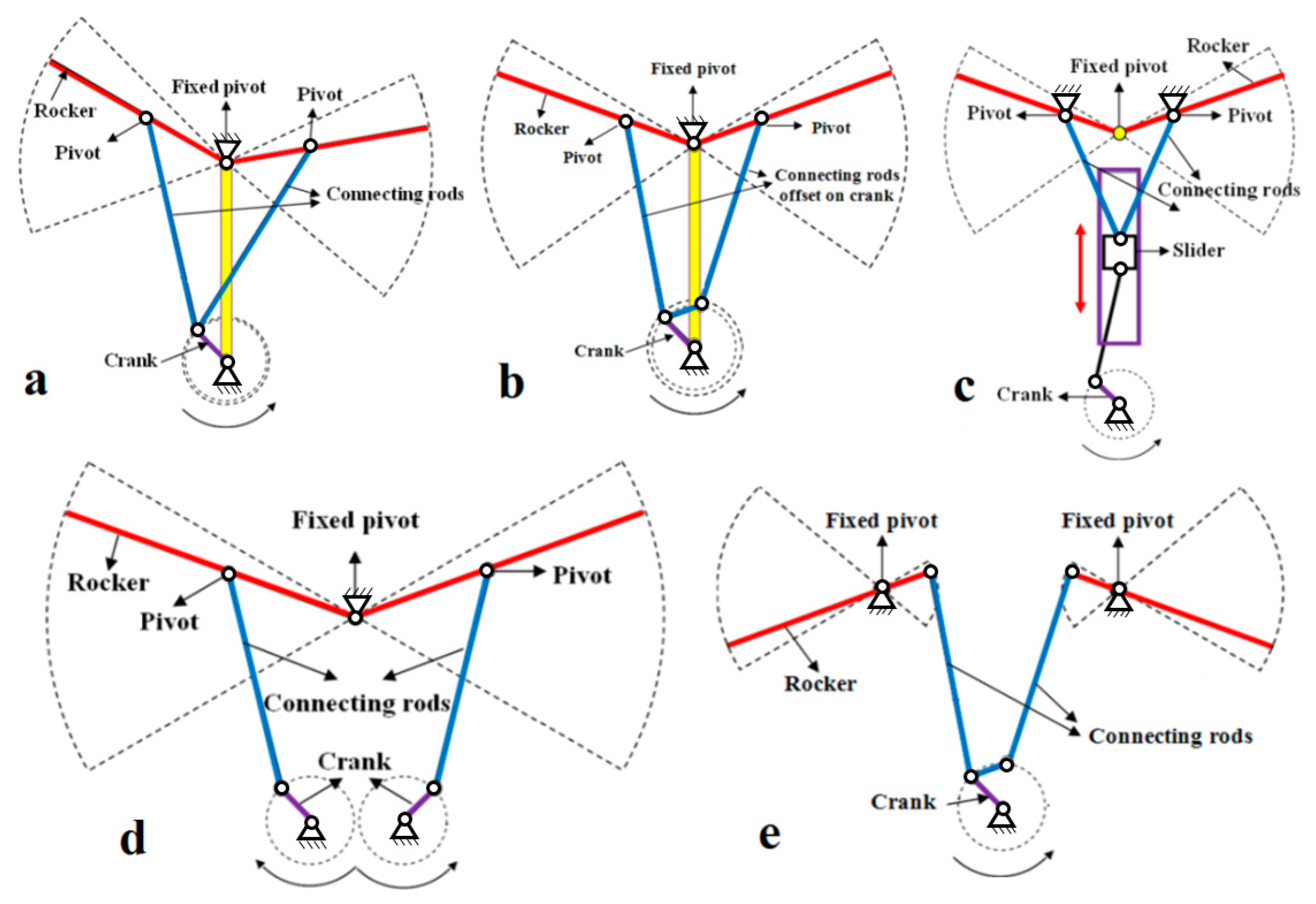
Figure 1. Schematic views of the (a) single crank mechanism, (b) single crank mechanism with an offset, (c) slider crank mechanism, (d) double crank mechanism, and (e) alternate configuration.
Drones 03 00073 g001
Figure 2. A schematic view of the mechanism status in flapping wing design process and proposed flowchart for flapping mechanism design process.
Drones 03 00073 g002
Figure 3. Schematic view of (a) slider crank, (b) alternative configuration, (c,d) hybrid mechanism.
Drones 03 00073 g003
Figure 4. (a) Two dimensional view of the flapping mechanism, (b) triangle consisting of three members of the mechanism, namely, crank, conrod, and connector member, and (c) created triangles from mechanism components.
Drones 03 00073 g004
Figure 5. Variations of the non-dimensional (a) position, (b) velocity, and (c) acceleration of the connector member as a function of the crank angle for different L/R ratios when the flapping frequency is set equal to 9 Hz.
Drones 03 00073 g005
Figure 6. Flowchart for determining the required flapping angle γ and adjusting the optimal angle of ξ.
Drones 03 00073 g006
Figure 7. (a) Variations of the flapping angle as a function of the crank angle for the five modes and (b) variation of the transmission angle as a function of the crank angle when considering the parameters of mode (5).
Drones 03 00073 g007
Figure 8. (a) View of the guidance bars and (b) view of created triangles of the guidance bars.
Drones 03 00073 g008
Figure 9. Variation of the λ as a function of the crank angle for different values of s.
Drones 03 00073 g009
Figure 10. (a) A schematic view of the analyzed part of the mechanism and (b) a schematic view of the used coordinate system.
Drones 03 00073 g010
Figure 11. Variations of the inertia (a) forces and (b) moment as a function of the crank angle.
Drones 03 00073 g011
Figure 12. View of aerodynamic forces and input torque where WTO is the weight and FAero denotes the lift force on the wing.
Drones 03 00073 g012
Figure 13. View of the position of the aerodynamic forces on wing where ACW is the aerodynamic center.
Drones 03 00073 g013
Figure 14. Variations of the (a) wing angular velocity, (b) lift, and (c) required torque as a function of the crank angle.
Drones 03 00073 g014
Figure 15. Overall view of the hybrid actuation mechanism and experimental tests.
Drones 03 00073 g015
Table 1. Advantages and drawbacks of the four-bar flapping actuation mechanisms.
Mechanism TypeAdvantagesDrawbacks
Single crankSimplest and lightestNeither completely symmetrical nor harmonic flapping wing motion
Single crank with offset Simple, light weight, symmetrical motion, and little phase difference between the flapping of the two half wingsCrossing each other of the rockers when they are in the same vertical plane
Slider crank Symmetrical flapping motionFrictional losses and difficulty in fabrication
Double crank Symmetrical flapping motionComplexity, high weight, and out of phase motion
Alternate configuration Providing the same flapping motion Cannot be used by biplane flapping wing, and non-symmetrical shape
Table 2. Determining the dimensions of the six-bar mechanism’s parameters.
ParameterMode (1)Mode (2)Mode (3)Mode (4)Mode (5)
R (mm)88888
a (mm)19.3817.6817.6816.6815.6
b (mm)151213.3513.3513.8
H (mm)45.7545.7545.7545.7545.86
C (mm)2020202015.6
L/R44444
γmax59.6951.255.655.962
γmin11.33−10.80−6.10
γmaxγmin48.366255.66262
ξmax117.9169144.1159.3136.1
ξmin73.2586.8282.9786.9972.94
ξmax − ξmin44.6582.1861.1372.3163.16
Table 3. Final dimensions of each guidance bar.
ParameterValueParameterValue
lu25 mme10 mm
ld20 mms15 mm

