Article

Reef Rover: A Low-Cost Small Autonomous Unmanned Surface Vehicle (USV) for Mapping and Monitoring Coral Reefs

by
George T. Raber
1,* and
Steven R. Schill
2,*
1
The University of Southern Mississippi, School of Biological, Environmental, and Earth Sciences, Hattiesburg, MS 39406, USA
2
The Nature Conservancy, Caribbean Division, Coral Gables, FL 33134, USA
*
Authors to whom correspondence should be addressed.
Drones 2019, 3(2), 38; https://doi.org/10.3390/drones3020038
Submission received: 8 March 2019 / Revised: 5 April 2019 / Accepted: 15 April 2019 / Published: 17 April 2019
(This article belongs to the Special Issue Drones for Coastal Environments)

Abstract

:
In the effort to design a more repeatable and consistent platform to collect data for Structure from Motion (SfM) monitoring of coral reefs and other benthic habitats, we explore the use of recent advances in open source Global Positioning System (GPS)-guided drone technology to design and test a low-cost and transportable small unmanned surface vehicle (sUSV). The vehicle operates using Ardupilot open source software and can be used by local scientists and marine managers to map and monitor marine environments in shallow areas (<20 m) with commensurate visibility. The imaging system uses two Sony a6300 mirrorless cameras to collect stereo photos that can be later processed using photogrammetry software to create underwater high-resolution orthophoto mosaics and digital surface models. The propulsion system consists of two small brushless motors powered by lithium batteries that follow pre-programmed survey transects and are operated by a GPS-guided autopilot control board. Results from our project suggest the sUSV provides a repeatable, viable, and low-cost (<$3000 USD) solution for acquiring images of benthic environments on a frequent basis from directly below the water surface. These images can be used to create SfM models that provide very detailed images and measurements that can be used to monitor changes in biodiversity, reef erosion/accretion, and assessing health conditions.

Graphical Abstract

1. Introduction

With growing alarm about coral reef decline, there is need for better and more consistent methods to monitor the spatio-temporal dynamics of these systems [1,2]. Coral reef managers rely on periodic surveys to assess changes in coral reef and benthic habitat conditions [3,4]. These include the detection and mapping of disease, bleaching, reef growth and erosion, and damage assessment after a storm or reef impact incidents (e.g., boat grounding or anchor chain drag). Various mapping technologies have been employed for mapping both shallow and deep areas of the ocean. Passive optical and active blue-green light detection and ranging (LiDAR) remote-sensing systems are used to map shallow benthic habitats [5,6]. Acoustic mapping systems, such as multibeam echo sounding (MBES) instruments, acquire both bathymetry (depth) and backscatter (intensity) data in wide swaths at deeper depths that can be used to map seafloor substrate characteristics [7,8]. While these systems are useful for mapping benthic habitats across broad scales, they do not provide the fine scale detail and high temporal measurements needed for monitoring small and subtle changes in the environment. Structure from Motion (SfM) is gaining momentum as a cost-effective and useful tool for capturing high resolution and temporal data for detecting change in benthic and coral reef habitats within small monitoring sites [9,10,11]. This technique involves capturing stereo photos acquired by scuba, snorkelers, or remotely operated vehicles (ROVs) that are processed through photogrammetry software to create high resolution orthophoto mosaics and digital surface models [12,13,14,15,16]. When geometrically corrected, these products can be used to detect centimeter changes in volume and surface area [17,18,19,20,21]. Scientists have used SfM models to accurately estimate a variety of ecological indicators such as linear rugosity, surface complexity, slope, and fractal dimension [22,23,24]. In an effort to design a more repeatable and consistent platform to collect data for SfM monitoring of coral reefs and other benthic habitats, we explore the use of recent advancements in open source Global Positioning System (GPS)-guided drone and camera technology to design and test a low-cost and transportable small unmanned surface vehicle (sUSV).

2. Materials and Methods

We designed the Reef Rover system with a number of goals and practical restraints in mind. First, the entire system had to be compact and easily disassembled for transporting, such that it could be suitable as checked flight baggage. This necessitated the system being under 50 pounds and less than 158 cm in total of length, width, and height when disassembled. In practice, we set a limit that the system not exceed one meter in length. Second, the system needed to have a very low draft in order to avoid potential obstacles such as shallow coral heads or other features close to the water surface. The system needed to be sufficiently stable on water to avoid being overtopped by small waves and water-resistant to avoid damage to the electronic components. Third, we set a target budget of approximately $3000 USD so the system could be affordable to resource managers and organizations with varying budgetary constraints. Our rationale for using this figure was that it is approximately the same cost as a typical prosumer or off-the-shelf airborne drone/unmanned autonomous system (UAS) with a basic camera and autonomous capabilities. Such systems are becoming common tools used in marine mapping and conservation efforts worldwide [13,25].
As a UAS, the Reef Rover consists of three primary subsystems that we describe in detail. First, the control and autopilot system; second, the boat vehicle itself (i.e., the floatation and propulsion equipment); and finally, the camera system. Several different versions of each system were developed and are discussed in the order in which they were tested. Very few changes to the control and autopilot system were made during our testing, with the majority of modifications and improvements made to the other two systems. Two versions of the boat vehicle design were made and are referred to as Version 1 and Version 2 in the vehicle section below.

2.1. Control and Autopilot System

The control and autopilot system is comprised of four components: the autopilot control board, GPS, electronic speed controllers (ESCs), and the radios. The first component is a Pixhawk flight control board running Ardupilot open source autopilot software equipped with several onboard sensors including a built-in compass and accelerometer. The Pixhawk that we purchased for this project was manufactured by 3D Robotics. For all versions of the Reef Rover system described in this research, an original Pixhawk flight control board was used (now referred to as Version 1, but at the time of acquisition no qualifier was used). It has since been discontinued, but the hardware specifications are also open source, and several copies and variants of the original version continue to be manufactured by other companies. Future tests will be based on a newer version Pixhawk 2.1, which runs a more recent version of Autopilot software and possesses improvements to sensors and sensor redundancies (i.e., compass, accelerometer, GPS, etc.)
The second and third components are the externally mounted ublox GPS (model LEA-6H) with compass used for waypoint navigation, and a pair of ESCs that control the maneuvering of the vehicle. Unlike ESCs in an airborne multirotor, these speed controllers have the ability to spin the motors in either direction in order to control the skid steering, which permits turn-in-place maneuvers. The final component is the radio communication between the operator and the control system on the vehicle. This includes a 3D Robotics two-way telemetry radio system (915 MHz) to communicate with ground station software from a tablet or personal computer and a one-way radio system that receives manual commands from the operator transmitted from a traditional remote-control radio unit. The latter is similar to those designed for unmanned aerial vehicles (UAVs) with two control sticks for when the operator wants to manually control the vehicle. All four components are housed within a modified Pelican case for waterproofing and attached to the topside of the vehicle.
The hardware and software combination used by the Reef Rover has been popular with hobbyists and researchers for nearly a decade, being assimilated into a large array of unmanned vehicles, from conventional airplanes, multirotor UAVs, and helicopters, to boats and even submarines. 3D Robotics (3DR), a commercial entity, eventually developed an off-the-shelf commercial UAV using similar hardware and software, called the 3DR Solo, which was released for sale to the public in May 2015. The Solo was based on a later version of the hardware than we utilized and a custom version of the Ardupilot software.
In the same way that an aerial vehicle can have different configurations that are all supported using the Ardupilot software and Pixhawk hardware (e.g., fixed-wing, quadcopter, hexacopter, etc.), there are several different configurations designed to support a boat vehicle. We used the Ardupilot Rover code and set up the Reef Rover for skid steering, which is the same configuration used for a track vehicle, such as a tank capable of a turn-in-place maneuver. When used in a boat, two electric motors are mounted on either side of a vehicle and the differential in the speed or direction of the motors determines, if and to what degree, the vehicle turns in the water. If wave action or currents push the boat off course, the autopilot code will compensate by turning the vehicle back toward its path, similar to an aerial vehicle being affected by wind. The skid steering configuration has two advantages. The first is simplicity, having no moving parts apart from the motor rotation (i.e., no rudder). This is similar to the differences in a helicopter compared to a multirotor where changes in the direction of travel are controlled exclusively by changes in the speed of the motors with fixed blades. Having fewer moving parts makes it easier to assemble and disassemble the vehicle. The secondary advantage is that it makes it easier to isolate and waterproof the electronic components.
Similar to a UAV mission, programed “float line” missions are uploaded to the Pixhawk that provide navigation waypoints for the vehicle to travel back and forth over a specific reef area while taking stereo photos. When planning to map an area with ocean currents, it is helpful to cover the entire area twice and provide as many intermediate waypoints as possible to keep the vehicle on course. We used ground control software Mission Planner (for PCs) and the Tower app (for android tablets and phones) to plan, upload, and execute reef mapping missions, which are both free and open source.

2.2. Boat Vehicle

The first version of the boat vehicle system consisted of a modified 2-Person Inflatable Boat manufactured by Sevylor. The sides of the boat were inflated separately from the bottom. We removed the bottom panel of the boat to mount a single medium-sized Pelican case (Model 1600) that was modified on one side and replaced with a center acrylic glass panel on the bottom to provide transparency for the camera system to image underwater. All components, including the control and camera system, were housed in the Pelican case along with the LiPo batteries that provided power to the motors and other electronic components. A frame constructed from PVC pipes was designed around the boat to support the partially submerged Pelican case and the propulsion system, which consisted of two brushed electric trolling motors (Newport Vessels, saltwater rated). The fully assembled vehicle can be seen in Figure 1.
The mapping capabilities of the Version 1 vehicle were tested above coral reefs located in West Bay, Grand Cayman in the Cayman Islands. Following extensive field evaluation and consultation with local coral reef experts and stakeholders, several design flaws were identified that made the vehicle difficult to deploy and use effectively. First, although the system was portable, the assembly and disassembly of the vehicle and components were long and tedious. Once inflated and assembled, the vehicle was approximately 2.2 m in length and 1.5 m wide, making it difficult to transport. The electric outboard motors were the heaviest component, each weighing approximately 9 kg. Being heavy and awkwardly large, the system had to be completely disassembled when transporting between test sites. Finally, having no keel or underwater weight, the boat suffered badly from stability issues and was highly susceptible to ocean current drift. These factors led to the camera occasionally not being fully submerged, which resulted in unsuitable images caused by blur and bubbles near the water surface. We attempted to solve this issue by adding a ballast, which exacerbated the weight and transport issues.
With these drawbacks in mind, we redesigned a second, more successful version of the vehicle system. The primary flotation element of the Version 2 vehicle is a foam bodyboard that is 3.5 cm thick, and measures one meter in length, and approximately 40 cm at the widest point. We used two Blue Robotics T100 thrusters as the new propulsion system, specifically designed for unmanned boats and submarines. These thrusters were not commercially available in early 2016 when the Version 1 system was designed. The thrusters were mounted on a custom-built aluminum strip frame bent to form a general upside-down “U” shape over the top of the foam board. Another aluminum strip frame connected the inverted “U” on the opposite side for underwater support, and finally a third set was mounted underwater perpendicular to the “U” which served as a keel. These aluminum strips are available and commonly sold at hardware stores both in the United States and the other Caribbean locations in which we tested the vehicle. The aluminum frame minimized salt water corrosion and was secured together using stainless steel bolts and wingnuts for fast assembly and teardown. Two smaller Pelican cases (Models 1120 and 1150) held the control system and batteries, respectively. Three holes were drilled in the Pelican case containing the components and waterproof electrical plugs were placed to fill the holes. One plug received the power from the batteries that were housed in the other Pelican case and the other two plugs sent the appropriate power to each motor dispatched by the ESCs. The fully assembled vehicle version 2 (Figure 2) measures 95 cm × 66 cm at the widest point (motor to motor) and weighs approximately 5 kg total without batteries, which makes it much easier to set up and transport. The draft of the vehicle when loaded with batteries and two Sony a6300 cameras and cases is approximately 31 cm. In the final configuration, without the external GPS antenna, it sits 16 cm above the water line at its tallest point. Table 1 presents a cost summary (in US dollars at the time of article submission) of the components used in Version 2.
In regard to battery power, each of the two versions of the vehicle used several 3-cell LiPo batteries, the number of which depended on the endurance needed for the desired mapping mission. These batteries provide power to both the propulsion system and the autopilot hardware. In Version 2, the batteries were placed in a separate small Pelican case to reduce and disperse heat. Using a configuration of four 5000 mAh batteries under normal operating conditions, a combined 20,000 mAh of batteries provides approximately 40 min of power to the vehicle. Similar to a UAV the vehicle could be recovered and provided with an additional set of fully charged batteries to continue operation (we often did this in our testing). The amount of area that can be effectively imaged in this 40 min time period varies based on the camera system, and the study area conditions, primarily the depth of the underwater features. We discuss this in greater detail in the results section.

2.3. Camera Systems

Our primary goal in testing each version of the Reef Rover was to produce a Structure from Motion (SfM) model at multiple coral reef locations and assess the quality of the orthophoto mosaic and digital surface model products. We tested four different camera systems, two on each version of the boat vehicle, for acquiring stereo photos necessary to build the SfM model. For each Reef Rover version, we tested two types of cameras: (a) a small, lightweight action camera; and (b) a mirrorless prosumer camera. The two camera systems tested on Version 1 are summarized in Table 2a, while those tested on Version 2 are summarized in Table 2b. The arrangement of the camera systems on Version 2 is presented in Figure 3. Our findings from the tests using the different cameras are discussed in greater detail in the results section.

2.4. Initial Vehicle Testing

While the primary goal was to collect stereo images of coral reefs to build SfM models, much of the time during the first field deployment of Version 1 was spent fine-tuning parameters that would permit autonomous data acquisition in a consistent and repeatable manner. Similar to other autonomous vehicles, a Pixhawk-controlled vehicle can receive a series of waypoint coordinates from an operator to map a pre-defined area. Using the waypoints as guides, the autopilot uses its sensors to guide the vehicle to the first waypoint, then each consecutive waypoint until it arrives at the final waypoint (Figure 4a). As previously mentioned, the Ardupilot Rover code that maneuvers the boat vehicle, was originally designed to drive in tank mode with track steering. However, unlike a land-based rover, an ocean-based rover must deal with ocean currents and wave action that can cause offset and navigational issues. One of the first problems identified was when traveling between waypoints under the influence of ocean currents, the vehicle did not follow a consistent straight line, being pushed by the current away from the direction of the next waypoint. This issue was exacerbated in Version 1 because this system was not capable of making a true zero-point turn, likely because of a combination of the vehicle’s weight (which increases inertia) and the rearward position in which the motors were placed, well behind all the weight at the front of the vehicle. After turning, the vehicle would attempt to self-correct, but take almost the entire length of a single-track line to do so. If the ocean current strengthened or slackened on a subsequent track, image undersampling would result for some areas while other areas might be oversampled (Figure 4b). This resulted in image data gaps and insufficient overlap required to create an effective SfM model. Following subsequent tests, the following autopilot parameters were identified and set to allow the vehicle to steer more accurately between waypoints (Table 3).
Upon further testing, we discovered it was effective to add extra waypoints along each track to ensure a more consistent vehicle direction and forward movement along each track (Figure 4c). This procedure was particularly useful when dealing with ocean currents. We were able to implement this technique by planning our missions as lines in ArcMap (Esri), then using the “Place points along line” tool to establish the extra waypoints along each track. The resulting point feature class was exported as a text file and manually edited to the specific format that autopilot requires before being uploaded to the system.
Due to the differences in boat vehicle design, Version 2 required additional parameter fine-tuning to achieve optimal performance (Table 3). These adjustments resulted in straighter navigation along each track and a faster speed than Version 1, which minimized the influence of ocean currents and made planning extra waypoints between tracks unnecessary. Unlike Version 1, the new version design placed the electric motors closer to the center of the now lighter vehicle (Figure 2 and Figure 3). This design made it very capable of making zero-point turns, and consequently the turning radius parameter was adjusted to under one meter. Supplement #S1 shows aerial drone footage of Version 2 completing an autonomous mission at the West Bay, Grand Cayman site.
Considering the variation of depth at each location, we experimented on spacing the float lines to ensure sufficient end and side lap (60%–70%) between images. This was challenging when ocean currents and subsequent drift of the vehicle resulted in not having enough overlapping images to create a gap free SfM model. Ultimately, we recommend a double grid approach, crossing the area twice in perpendicular directions, but without the additional waypoints between tracks (Figure 4d).

3. Results

Both versions of the Reef Rover were tested at two Caribbean locations. Version 1 was tested over coral reefs located at West Bay, Grand Cayman in the Cayman Islands in November 2016 and January 2017 (Figure 5a). The easy accessibility to this site proved vital in the early experimentation portion of the study. This location allowed for easy setup, dismantling, and retrieval of the vehicle in case of malfunction.
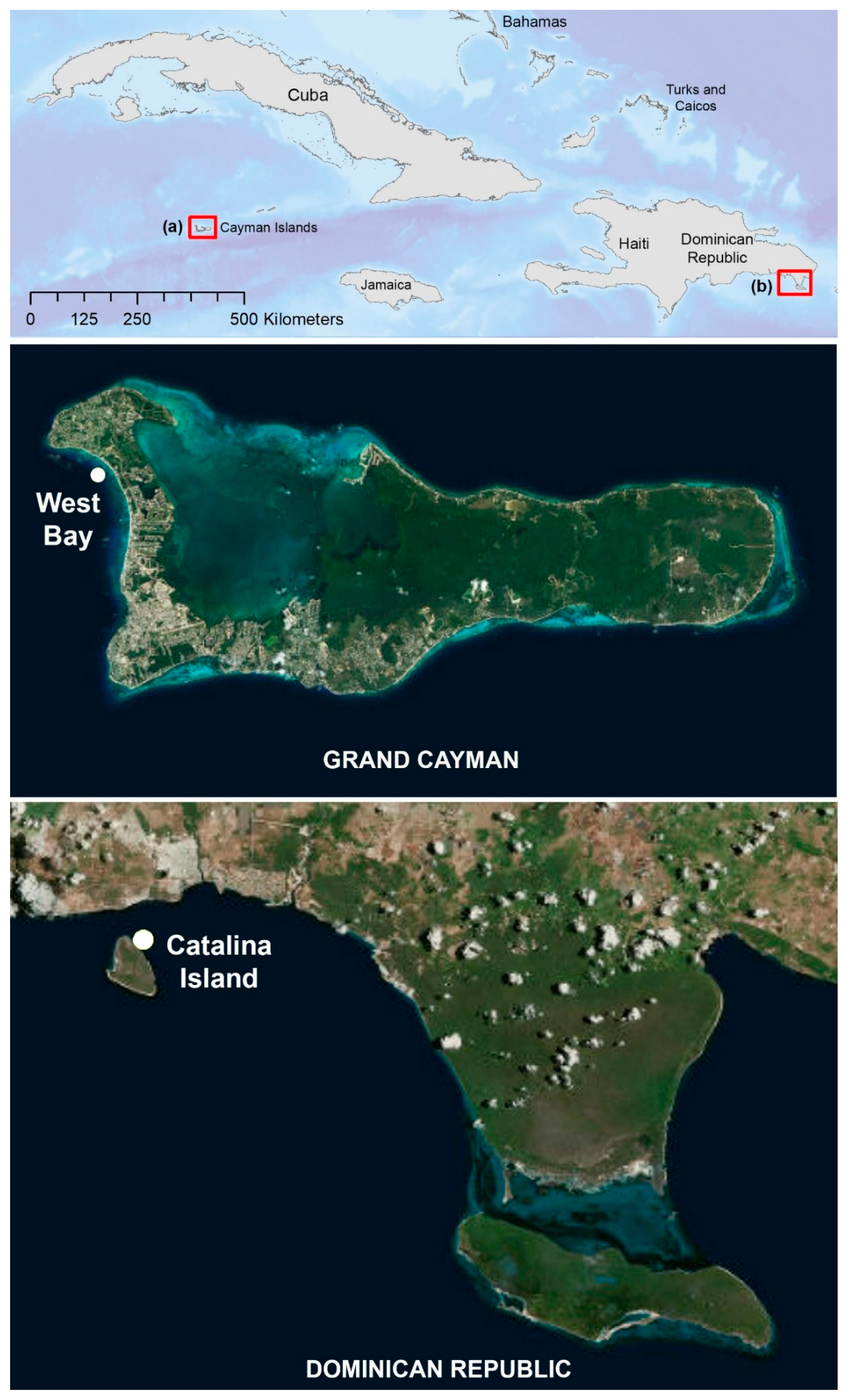
Following the design and testing of Reef Rover Version 1, the same location at West Bay, Grand Cayman was used to test Version 2 in November 2017. The subsequent field campaign proved more productive due to the new design, which facilitated set up and dismantling, transport, and overall execution, which resulted in more accurate products.
Additional testing of Version 2 occurred in May and August 2018 at a second coral reef location off the northeastern coast of Catalina Island, approximately 2.5 km off the southeastern shore of the Dominican Republic, close to the town of La Romana (Figure 5b). The easier setup and lower failure rate of the Version 2 proved to be important characteristics for mapping in more remote locations, such as Catalina Island. During the August 2018 field campaign, we focused on acquiring SfM models of Elkhorn Coral (Acropora palmata) colonies in an area where many had been damaged by the recent Category 1 Hurricane Beryl, which had passed nearby a month prior to our field work.

3.1. Results of Testing Version 1

Our initial objective in building Version 1 was to compare SfM models using two different camera systems: a smaller YI™ 88001 16MP Action Camera and a larger mirrorless Sony a6000 with a 16mm lens. Unlike many action cameras on the market, the 16MP Yi camera has the ability to set image acquisition parameters, such as ISO and shutter speed, although doing so requires uploading of 3rd party firmware to the camera. The Sony a6000 has a 24 MP APS-C format sensor. The Yi camera ($150 USD) is much less expensive than the larger mirrorless a6000 ($600 USD); however, both cameras allow the shutter speed to be controlled, which is critical for minimizing image blur when taking underwater photos. No attempt was made to use artificial illumination when taking the photos, but we relied on available sunlight through the water column.
When testing the cameras to collect rapid subsequent images, each camera was set at the fastest interval capable for the length of the planned mission, which was typically between 20–30 min. For both camera models, the maximum rate was once every 1.5 s. In practice, for both models, the write buffer would occasionally get filled (once every several minutes) and would result in an image interval delay longer than 1.5 s. Both cameras were tested at various depths within the same reef area, knowing that shallower areas would require closer track lines to achieve adequate overlap. We used the mission planning Android app, Tower, to specify the lens and automate the process of calculating the distance between mission lines that is required for a desired overlap (e.g., 70%), and an average depth of the features below the camera (e.g., reef). Tower has a preset lens configuration for the Sony 16mm lens, which is used to determine proximity of the tracks based on a given “flying height” for which we input the depth (i.e., the software is designed for aerial platforms). Although a lens configuration was not available for the Yi camera, the corresponding parameters were manually set up using the software. However, setting a consistent depth proved problematic, especially in areas where the reef came near the water surface (i.e., <2 m).
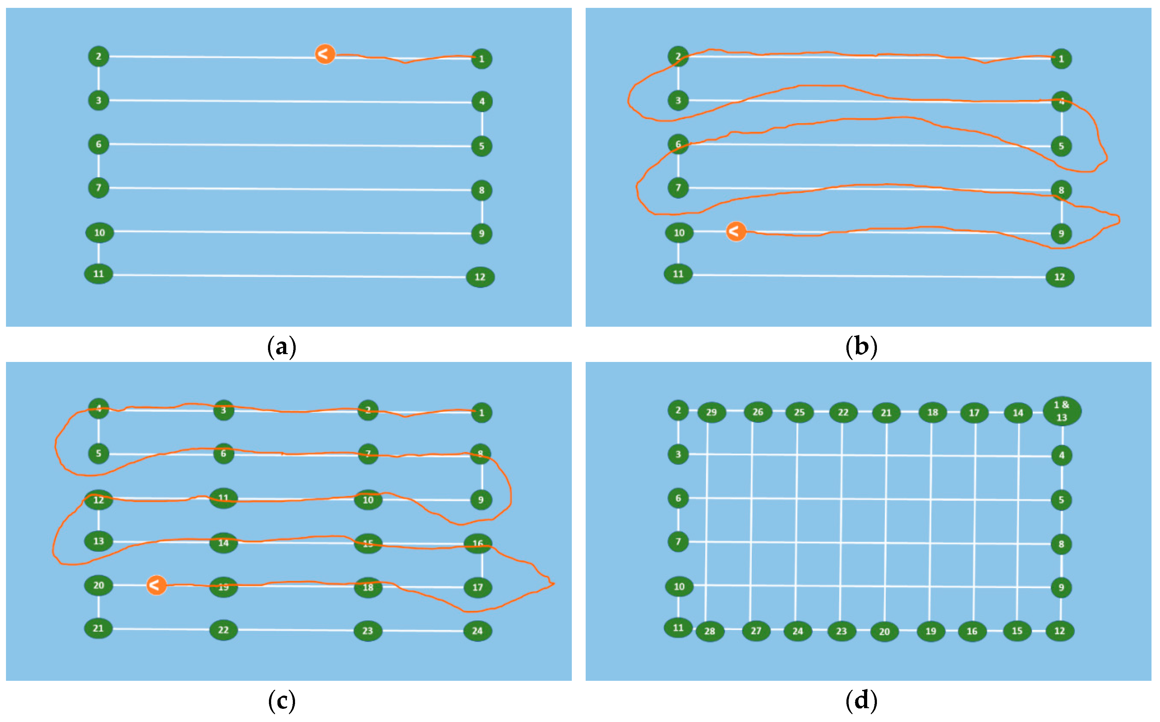
Although the Tower app does compute the necessary distance between survey lines, in order to achieve acceptable overlap at an expected depth, we often found it useful to calculate these numbers manually for planning custom missions, such as double grid patterns described earlier in Figure 4. The formula for calculating the dimension of an individual camera footprint is the tangent of one half the field of view (FOV) angle times twice the depth. Even though the lens is round, the sensor is not, so there is a different angle associated with the length and width of an image. The field of view angles for an APS-C sensor using a 16mm lens are 73 degrees for the wider dimension (width) and 52 degrees for the narrower dimension (length). Once the length and width are calculated for a given depth, the overlap can be calculated as 1 minus the desired overlap (e.g., 0.7) times the wider dimension; we only tested orienting our cameras with the wider dimension perpendicular to the survey tracks. The nominal ground sample distance (GSD) for a given depth is calculated as the image dimension divided by the number of pixels for the corresponding dimension. Table 4 presents these calculations for the Sony camera tested set at a focal length of 16mm. All units in the table are given in meters (m) except ground sample distance (GSD), which is listed in millimeters (mm).
Images were collected over the same reef area using both cameras and copied directly from the memory cards to a PC to build the SfM models using photogrammetry software. Although both camera models lack an onboard GPS, we did not attempt to geotag the images for our first test comparison. Geotagging involves assigning a coordinate to each image based on the GPS location reported by the autopilot at the same time as the image was acquired and can facilitate the construction of the SfM model. Our initial attempts to create SfM products from these datasets were not successful. However, we explored several different data acquisition parameters and processing options and learned many important lessons through trial and error, which guided future efforts and may assist others attempting similar research.

3.1.1. Sun Angle Relative to Acquisition

The sun angle relative to the water surface proved to be a critical image collection parameter. When the sun is at higher angles relative to the horizon (>25°), the action of the waves, even if very calm, will produce an unpredictable, constantly changing light pattern across the underwater surface that is being imaged. This presents an unsurmountable issue for the SfM software as it relies on identifying similar patterns (i.e., keypoints) that represent the same objects in overlapping images. The differences in light patterns from image to neighboring image prevents this recognition from occurring and/or produces false positives in areas without significant distinguishing features (e.g., sand). Others have noted this same issue in terrestrial or aerial SfM work [13,26,27].
The only acceptable solution to this issue was to acquire imagery when the sun angle was low (i.e., <25° from the horizon), either in the early morning or late afternoon. Alternatively, one could acquire images on an overcast day with diffused light conditions that would minimize the changing light patterns that are caused by high angle and direct sun rays. However, the availability of light is diminished underwater and acquiring images during overcast days or at lower sun angles can often prove problematic, particularly in the case of using the action cameras (discussed below).

3.1.2. Depth of Underwater Features

Another topic of our research considered depth and determining how deep the camera system could map and model the reef environment. We were aware that our cameras, being mounted to the vehicle at or slightly below the water surface, would be limited in their ability to capture recognizable images at deeper depths as the visibility of the water column diminishes at greater depths. Pure water, although mostly transparent, does absorb light. Ocean water always has other materials both dissolved and particulate matter suspended within it. Due to the nature of SfM, it is impossible to create a model if there are no distinguishable features. Although no attempts were made to quantitatively measure water clarity at the test sites, the clear waters of the Cayman Islands provided an environment where we could collect data at depths of less than 10–15 m that could effectively be used to create SfM models. We did not attempt any tests beyond this depth range.
In addition to the light penetration issue presented, depth variability of benthic features was also an issue, particularly at the Grand Cayman site. In our primary test location, the reef structures varied from being about 8 m deep at the deepest locations (mostly sandy areas) to coral reef heads that were within 1 m of the water surface. This presented the problem of motion blur in the images (e.g., shutter speed too slow to capture detail at close proximity) as well as not having sufficient image overlap to adequately represent features in shallow areas. Since building SfM models relies on computer vision, images acquired closer to the subject require more overlap than subjects that are further away (given the same camera FOV or focal length). This is because a feature closer to the camera appears to change more with slight changes in perspective than an object that is further away from the camera.
Depth also complicates motion blur issues. Motion blur is often confused with focus because it can look similar in an image, but motion blur is created when an object moves within the image frame during exposure. In context of the Reef Rover, motion blur is more of an issue in the near field as the apparent motion of a close object is greater than an object further away (i.e., at greater depth). For example, it is easy to take a picture with little apparent motion blur in an aircraft moving hundreds of miles per hour when flying at 3000 m above ground, but it would be nearly impossible to take a picture without motion blur of a stationary object if one was only flying a meter or so above the ground. Taking a reliable image in 1–2 m of water with a vehicle moving at multiple meters per second without much light was an issue. We found a shutter speed faster than 1/1000 was able to eliminate motion blur at this depth. To compensate for this, we effectively increased ISO sensitivity by setting the camera to automatically set the ISO value to any value at or below a certain ISO threshold (ISO < 1000) on each exposure. When using the APS-C format Sony cameras, this allowed for acceptable images to be acquired; however, when using the action cameras, the image became very grainy or blurred. When imaging deeper areas, particularly in areas where no imaged surface was less than 2 m below the water, a slower shutter speed (1/640) produced acceptable images using the same ISO settings.
When considering focus and depth of field settings, the action cameras are fixed focus with a wide lens (i.e., fisheye) and large depth of field. This can have advantages but image quality across varying environments generally suffers from having one fixed setting. After testing the Sony cameras, the optimal setting was automatic aperture and AF-C mode, meaning the camera attempts to search and focus continually. Occasionally, this yields an out-of-focus image if the camera needs to hunt for a focus point while the shutter is open. The depth of field was only an issue in cases where the subject was very close to the camera lens (<~1.5 m), particularly since larger aperture values were required in the lower light conditions.

3.1.3. Action Camera versus Larger Format Camera

Overall, the image quality acquired from the action cameras (both the Yi™ and the GoPro™) were much poorer than those acquired with the Sony a6000. We were not able to create suitable SfM models from any of the images collected by action cameras when mounted to either version of the vehicle. Like many action cameras, they both utilize a 1/2.3” sensor (crop factor of 5.62 compared to full frame), which is over 10 times smaller than the APS-C sensor in the Sony a6000 (1.5 crop factor). This means the individual size of the detectors is smaller, allowing less light to come into contact with the sensors. Therefore, the APS-C sensor will have less noise (and subsequently provide richer detail) when using similar camera settings (particularly ISO).
Another important consideration is the type of shutter used in the camera. The action cameras operate using a rolling shutter, whereas the Sony cameras use a mechanical shutter (when taking still pictures rather than video). A mechanical shutter image is captured by taking a snapshot of the entire scene at a single instant in time, similar to the way film cameras work. A rolling shutter camera operates by scanning across the scene rapidly, either vertically or horizontally, like a television or computer monitor reproduces an image on screen. This concept is different than shutter speed, which in the case of a rolling shutter refers to the amount of time a single detector on the sensor is exposed to light for a particular image. When using a rolling shutter, the image is not acquired all at the same time, and if the camera is moving faster than the scan rate, there will be distortion in the image. This effect is often referred to as the “rolling shutter effect” and can be difficult for SfM software to handle as it attempts to build a model. In cases where the effect is mostly caused by motion in a constant direction, it can typically be accounted for in the software as a camera option. However, in the images collected using the action cameras, oscillations were created both by the electric motors themselves, and by the effect of the autopilot constantly correcting the position of the vehicle.
Upon inspection of the images acquired using both action cameras, we noticed evidence of the rolling shutter effect, which was likely the reason these data did not provide an acceptable SfM model. Although others have reported success using action cameras [10,14,21], this is likely due to the ability of a diver to hold a position and acquire a more deliberate still image. We did not attempt to stabilize the image through mechanical techniques (i.e., powered gimbal) as it would have added significantly to the cost and, given the budget restraints, was not practical in the underwater setting in which we were working in.

3.1.4. Camera Capture Interval and Heating Issues

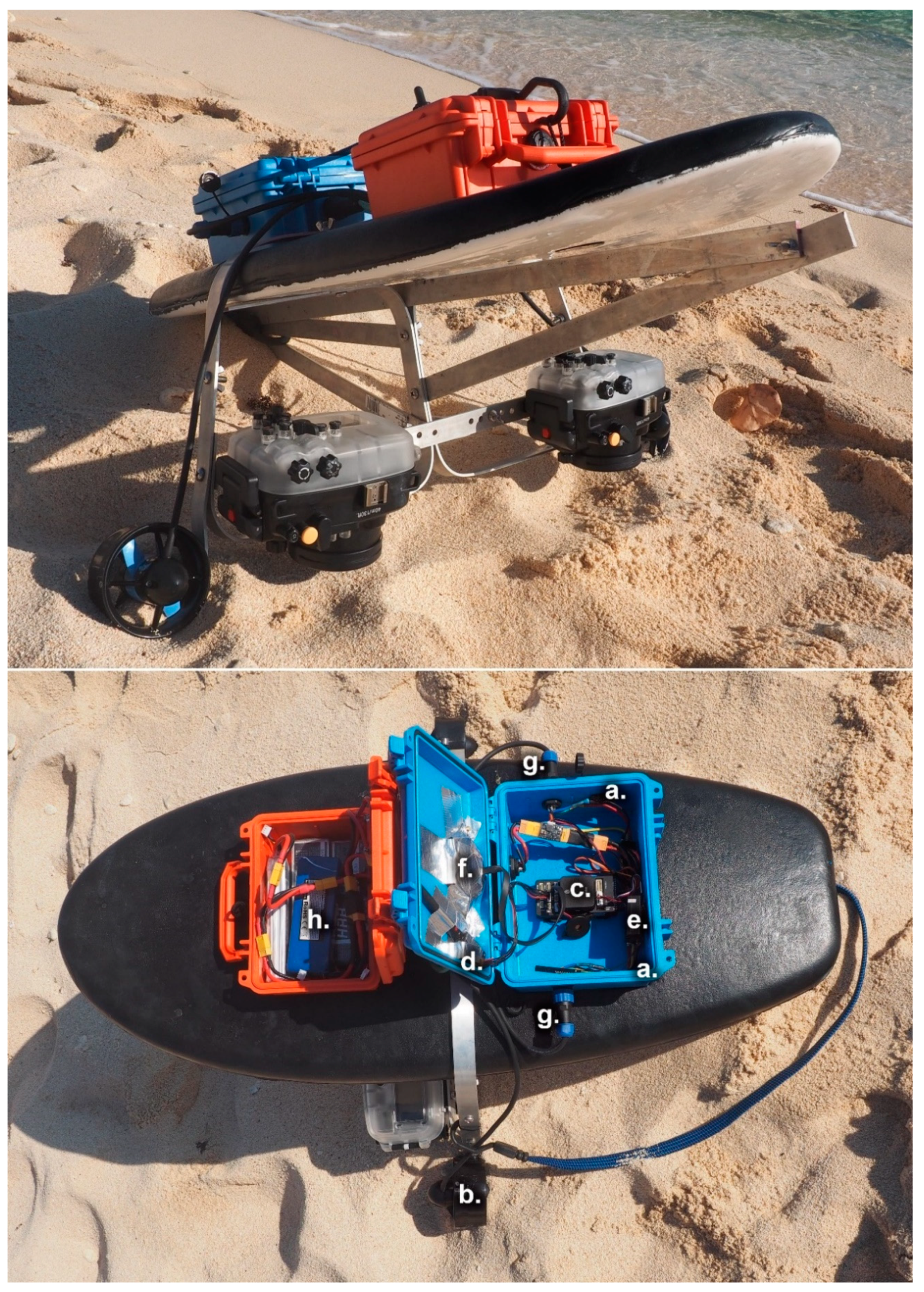
One of the primary camera issues tested on the Reef Rover Version 1 was having insufficient image overlap due to the increased speed of the vehicle that prevented getting pushed too far off course by ocean currents. We attempted to solve this by adding closely spaced waypoints along each track; however, the slow interval of one frame every 1.5 s ultimately did not provide enough overlap. We attempted to solve this problem in two ways. First, the camera needed to be capable of acquiring images at a more rapid interval, and second, a second camera needed to be mounted on both sides of the vehicle to ensure sufficient overlap between images. The subsequent design of the Reef Rover Version 2 upgraded the systems to a pair of Sony a6300 cameras that provided the capability of acquiring up to three frames per second in continuous shooting mode. When the camera is firing at this rapid interval, the memory buffer does fill up and often changes the rate of continuous capture to match the maximum rate at which the images can be written to the memory card. After examining our data from the a6300 cameras, we found the effective capture rate to vary from approximately 100–170 images captured per minute (i.e., the capture interval was between 0.35–0.6 s when averaged over a minute). We suspect that the effective rate is determined by a number of factors including the quality of the SD card, the camera settings, and the complexity of the imaged scene (particularly when capturing JPEGs). For all data missions we used a SanDisk Extreme Plus SD card 90MB/s U3 Class 10.
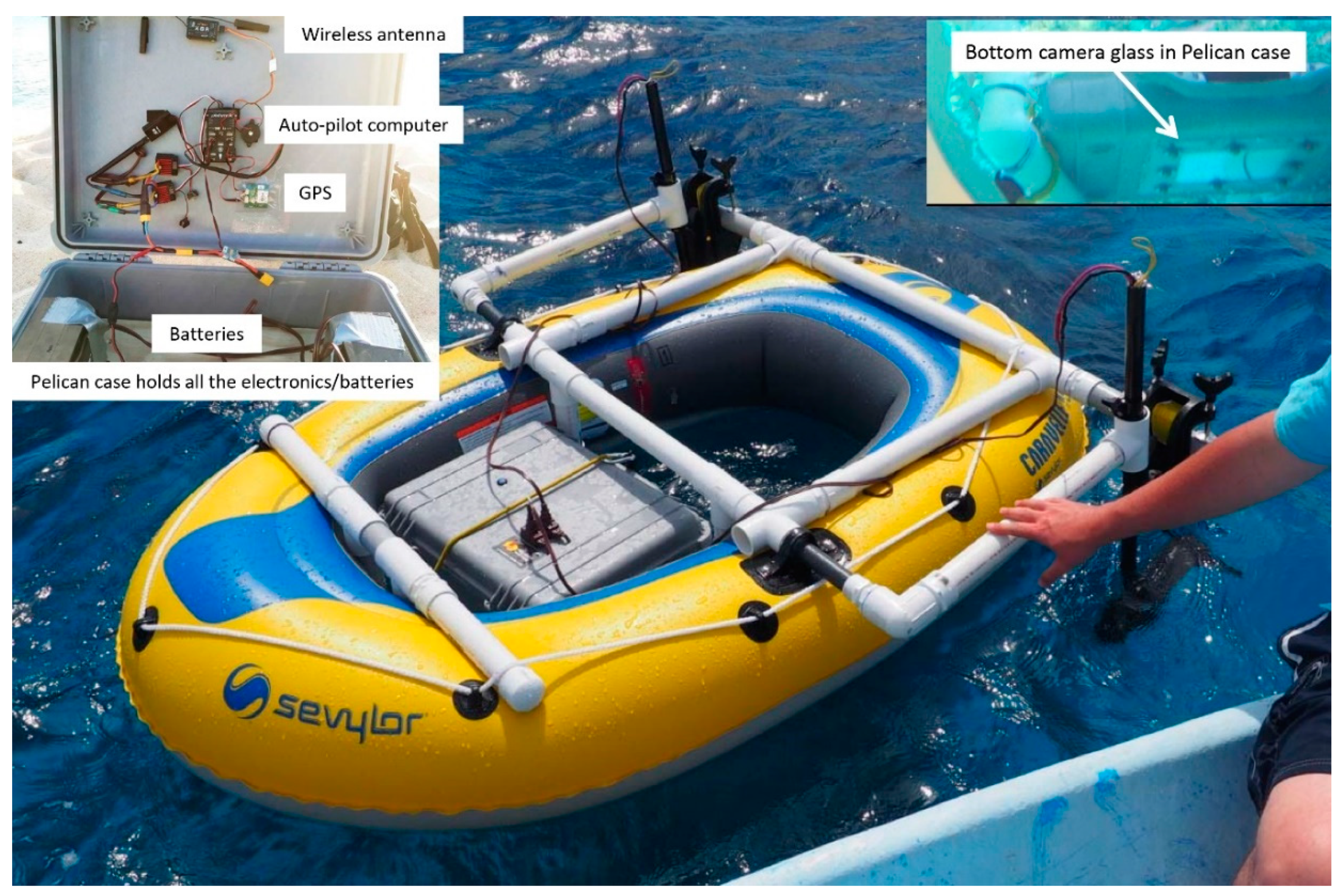
Considering that the Sony cameras are not waterproof, a Miekon waterproof housing was used and mounted on the bottom of the vehicle frame. While firing at the most rapid interval during a mapping mission, the cameras inside the housing would eventually overheat and report to the user a need to cool down. Testing of the camera outside the housing did not result in overheating. The overheating would cause a delay in the mission for approximately five minutes until the camera sufficiently cooled to resume normal operation. When using the a6000 shooting at a longer interval (1 frame/1.5 s), overheating occurred after 50–60 min of continuous shooting. However, the a6300 would overheat after about 30 min of continuous shooting since it was shooting at a much faster interval. While this may not be a problem for mapping smaller areas (<50 m × 50 m, with depths >2 m), the overheating issue presents a practical barrier for mapping relatively larger areas that would take longer than 30 min to acquire.

3.1.5. Structure from Motion (SfM) Processing and Data Volume Issues

Data post-processing was completed using Pix4Dmapper, a widely adopted photogrammetry software originally designed to create drone-based SfM models. Using this software, users can specify a large number of processing parameters as well as the types and formats of the outputs generated. We present how changing these processing parameters affected our ability to create SfM models successfully. Although we utilized Pix4Dmapper there are other software programs that operate in a similar manner, and have similar processing parameters. These include Agisoft Metashape (commercial license) and Open Drone Map (open source license).
For each set of images acquired during a data collection effort, we created a 3D point cloud, 3D mesh, digital surface model, and orthophoto mosaic using Pix4D’s “3D Maps” template settings. First, a user must specify the camera settings (e.g., sensor size, pixel width and height, focal length, etc.). These settings are typically contained within the EXIF metadata for each image and automatically identified by Pix4D. If necessary, these settings can be specified manually. Once the camera settings have been entered, the software uses computer vision techniques to identify the same object across multiple overlapping images. These identified object locations are referred to as “keypoints” and are used to infer the relative position of each “camera” or image using the camera parameters—a term referred to as camera calibration. Camera calibration can be aided if the GPS position for each camera is known, because the software can eliminate pairs of images that would not share any keypoints because the images do not overlap. Without the coordinate information, the software must check each image against every other image for corresponding keypoints—a process that is computationally intensive and very tedious. As an alternative, Pix4D can use other strategies to speed processing and minimize image search time by eliminating pairs of images that are not neighbors. These include using the time stamp information of each image and comparing overall image similarity. Since the image data collected with Reef Rover Version 1 was not geotagged, both of these options were selected in an attempt to speed processing in the selection of keypoints.
Another processing parameter we adjusted in relation to the keypoint identification is the scale of the images used in the search process. The user has the option of using the full resolution image, or resampled versions at specified intervals (i.e., use half the pixels, one quarter of the pixels, etc.). Using the images at full resolution will take longer to process; however, the location of the keypoints will be more precise. Also, a different number of keypoints are often identified by the software when processing at varying resolutions. When there are not enough keypoints, the camera positions will not be able to be inferred by the software (i.e., calibrated). In an extreme case, if not enough camera positions are inferred, the software is not able to find a solution and stops processing the images. After the cameras have been calibrated, a second attempt is made to find a greater number of matching points using the camera positions to aide this process. This process results in a dense point cloud from which a 3D mesh is created by connecting the matching points. A resulting orthophoto mosaic is created by projecting the point cloud onto a 2D plane.
Throughout this process, an important issue to keep in mind is computer processing power to handle the large data volume created from SfM missions. Our missions using the Reef Rover Version 1 were planned at time periods ranging from 25–40 min and collected images every 1.5 s. Each mission produced approximately 1000–2000 images, and processing these data became very time and resource consuming, depending on the processing power of the computer. For example, on a desktop machine with an Intel Core i7 3.4 GHz CPU, 64 GB of RAM and a 4GB graphics card with 1024 Compute Unified Device Architecture (CUDA) cores, a mission dataset with roughly 2000 images, took several days of processing time. In comparison, processing the same number of aerial drone images usually takes 5–8 h on a similar machine. The primary reason the processing took much longer is because images were not geotagged and the processing software could not take advantage of the geolocation of the images.

3.1.6. Version 1 SfM Model

A successful SfM model was created using the Reef Rover Version 1 from a dataset of 1674 images acquired from the Sony a6000 in the late afternoon (around 4 pm local time) at the West Bay, Grand Cayman site in January 2017. As previously mentioned, this mission was only partially automated, with a swimmer guiding the vehicle to image areas for supplemental coverage. However, all the images were acquired from the Reef Rover platform using the camera mounted in the waterproof case in the same position as under normal operation. Figure 6 presents several renderings of the outputs centered over an Elkhorn Coral (Acropora palmata) colony approximately 1.5 m in diameter.

3.2. Results of Testing Version 2

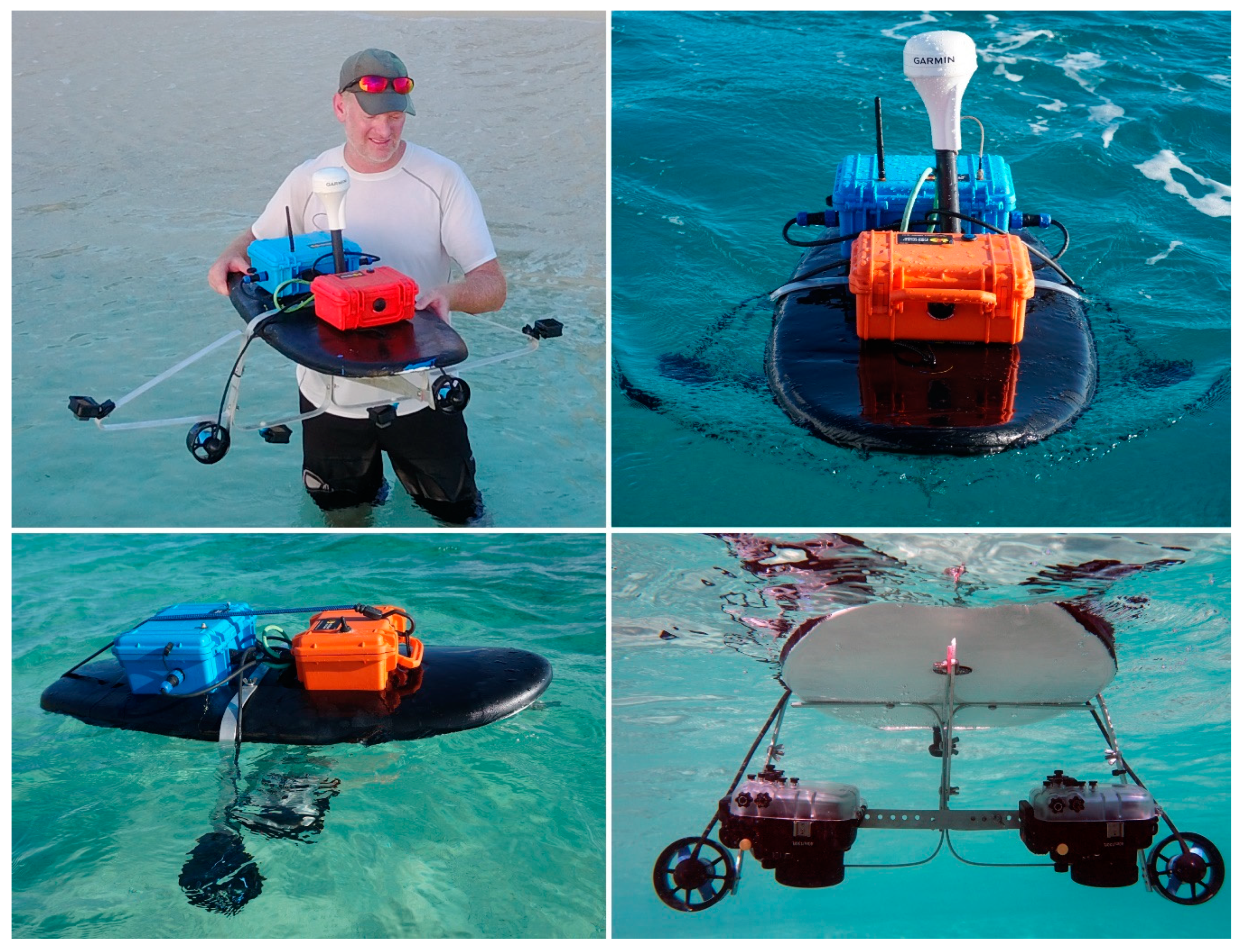
Following the setup and parameter tuning of the redesigned Reef Rover Version 2, several mapping missions were conducted using the GoPro™ Hero 6 Black cameras in the early morning and late afternoon over a 3-day period at the Wet Bay, Grand Cayman site in November of 2017. Our objective was to test if adding multiple cameras and upgrading the action camera (i.e., better sensor and faster shooting interval) would provide better quality and sufficient overlapping images to successfully process the SfM models. Compared to the single Yi camera test, four GoPro cameras were mounted and spaced evenly 30 cm apart (Table 2b and Figure 3 upper left) to test if additional cameras taking more simultaneous overlapping images would aide in the processing of SfM models.
The GoPro Hero 6 Black camera has a setting called “Protune”, which allows a user to set a few additional parameters such as white balance, ISO, and sharpness. We set the Protune “White Balance” setting to “Native” since this option yields a minimally processed data file. We experimented with a range of shutter and ISO settings on the GoPro camera over the duration of our tests. Similar to the tests with the Yi action camera, we were not able to produce any successful underwater SfM products with the GoPro images using any of the Pix4D processing techniques discussed in the previous section. Although the image quality of the GoPro did appear better than the Yi, it was still not as sharp as the images that were later captured using a Sony a6300 camera. The software simply did not find adequate keypoints due to both clarity of the images and enough image overlap. The shallowness of some of the reef features near the water surface also contributed to insufficient overlap and image blur.
Our test of the Reef Rover Version 2 in the Dominican Republic in May 2018 proved to be the most successful—applying all the knowledge we had gained from the previous tests. We executed several fully automated missions over a few different types of coral reefs off the northeastern shore of Catalina Island. The average depth at the site varied between 5–8 m, which was deeper than the study area we had tested on Grand Cayman, which averaged around 2–4 m. We found that the deeper depths created sufficient overlap suitable for mapping and missions could be similar to those depicted in Figure 4c with tracks 1 to 1.5 m apart. At this location, a 30 × 30 m square area was mapped using the Reef Rover traveling at an average speed of 3 m/s in approximately 12 min, covering a total distance of approximately 2000 m. Even though the vehicle was set to cruise at 5 m/s, slowing occurs upon approaching each turn waypoint and the vehicle rarely reaches full cruising speed before arriving at the next waypoint. In practice, the vehicle would be under power for closer to 15–18 min in a 30 × 30 m scenario considering launch and initial testing time plus travel to the start of the mission from the base. Such a mission would yield approximately 1100 images on each camera, or 2200 images total when using two cameras.
Over a larger 50 × 50 m square area, a similarly planned mission would take approximately 25 min, traveling at a slightly faster average speed. However, if deployment times start to exceed 30 min, the camera overheating problem may cause an interruption of the mission. Consequently, we found that 30 min of mapping time represents the largest area that could be practically executed in a single non-interrupted mission using Version 2. A 30-min mission would produce approximately 2500 images for each camera, or 5000 images in total. It is important to remember when planning a mission, the operator should also consider environmental parameters such as ocean currents and wind that may increase mapping time.
At the Catalina Island test site, we exclusively utilized the a6300 cameras because of the faster shooting interval and superior quality images. Our first deployment in May 2018 used a single camera, but in August 2018 we added a second camera to increase image overlap. In each case, the cameras were set to acquire at 1/640 or 1/800 shutter speed with an ISO of 400 and automatic aperture (i.e., shutter priority mode). Although the a6000 cameras have an automatic underwater setting that we used when testing them, the a6300 cameras lacked this setting. Prior to acquiring images with the a6300 cameras, we manually held one camera underwater simulating the conditions during actual data collection and manually adjusted the white balance to a visually pleasing value using the color temperature setting. The images during the automated missions were geotagged based on the GPS log from the Pixhawk autopilot using a software program called Mission Planner.
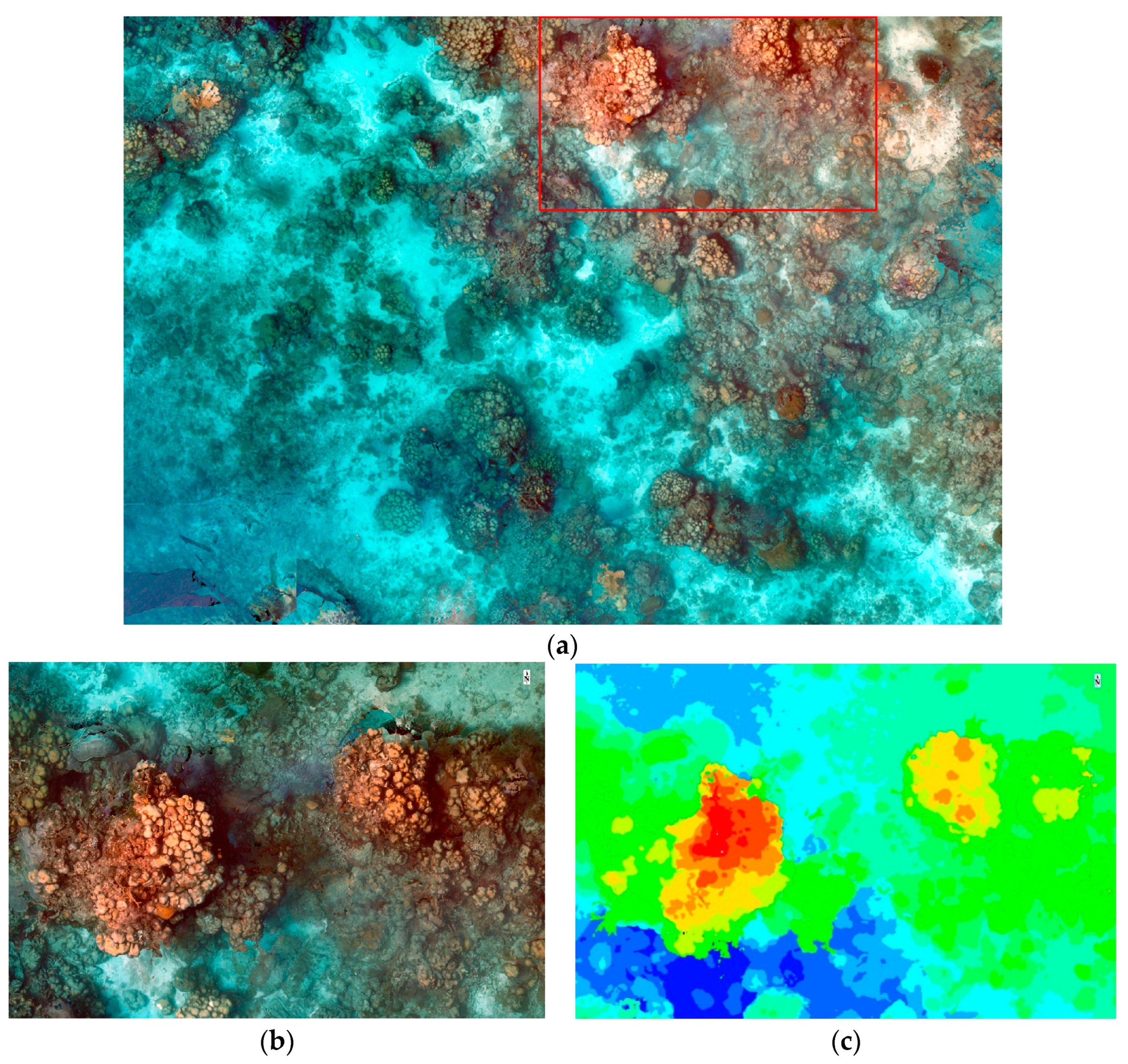
During the May 2018 test at Catalina Island, a single a6300 camera was used to map an area approximately 15 × 20 m that was largely dominated by Boulder Star Coral (Orbicella annularis). Several automated missions were completed over this area, however the stronger ocean current at the site tended to push the vehicle off course, resulting in the need to revisit some of the areas immediately after the automated mission finished. The track of the vehicle can be observed in real-time using the Tower app on the tablet, so any resulting gaps can be later covered manually. In general, it is easier for the vehicle to follow tracks that run parallel to the ocean current rather than perpendicular to the current where drift is more likely to occur. Mapping this area produced approximately 2000 images. We used these as input into Pix4D to generate a SfM model. The geotagged images initially failed to yield a SfM model despite several attempts to adjust the image scale during keypoint generation and adjusting the assumed accuracy of the initial camera position. Pix4D was able to generate the ortho shown in Figure 7 using only image collection time and image similarity to generate the keypoints.
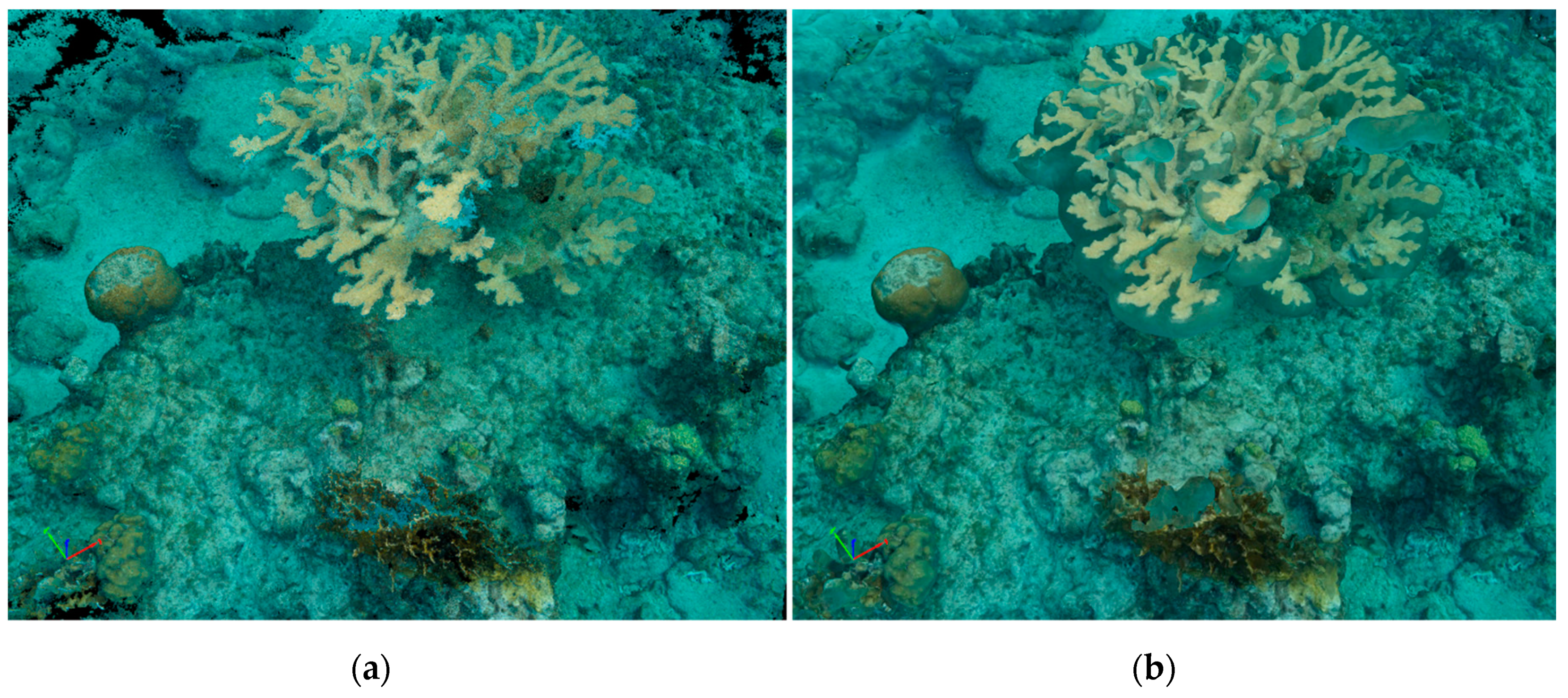
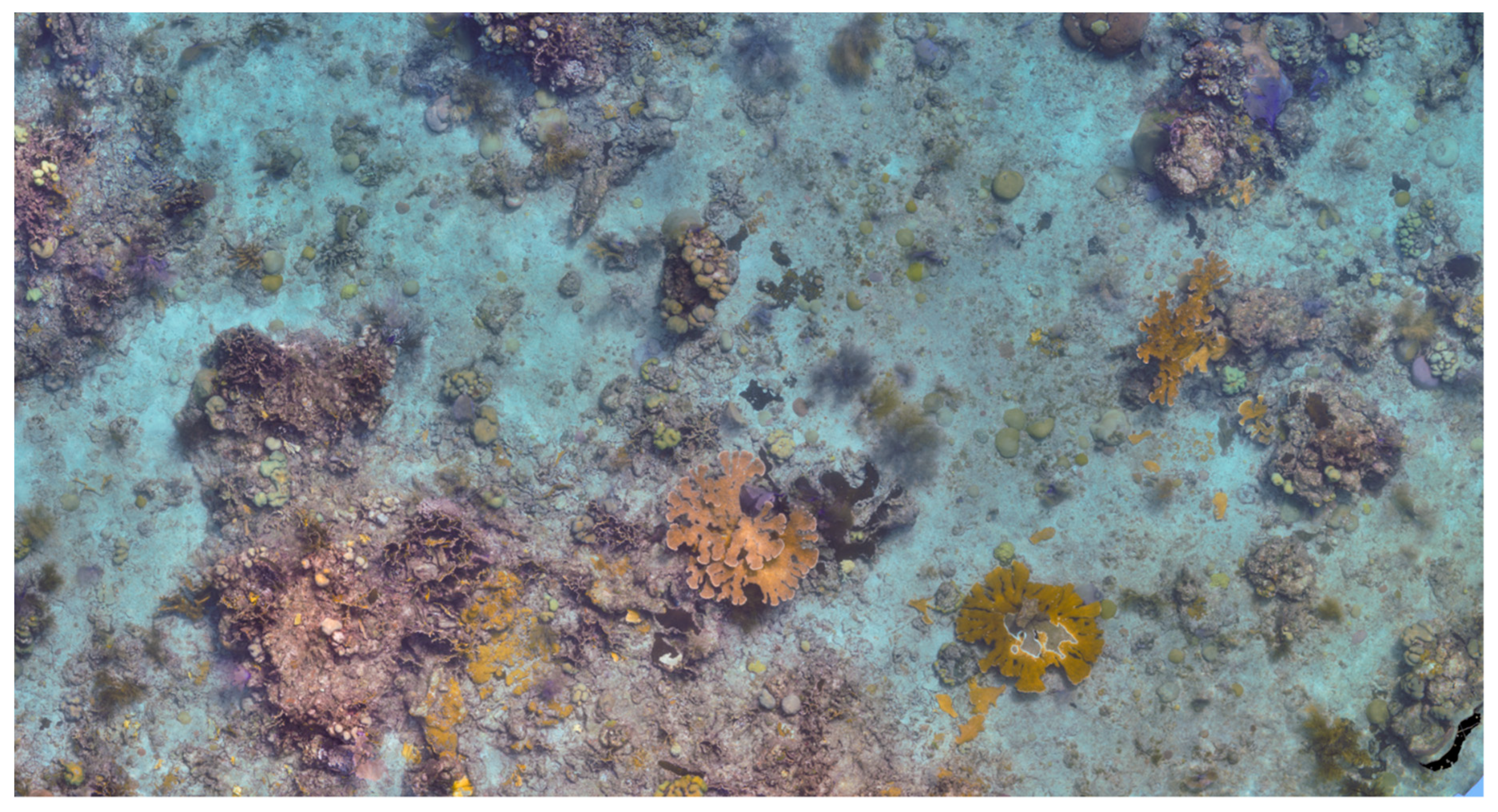
On our return trip to Catalina Island in August 2018, we focused on imaging areas with more coral cover and rugosity. We imaged three areas that were roughly the same size to each other and slightly smaller than the area imaged in Figure 7 (May 2018). We decided to forgo geotagging the images until we could retrofit the system with a higher accuracy GPS unit. The mapped areas had similar depths to the previously successful imaged area (i.e., 5–8 m deep) and included an area dominated by Boulder Star Coral (Orbicella annularis) and Pillar Coral (Dendrogyra cylindricus) that can be seen in Figure 8. A video flythrough animation of the pillar coral 3D mesh for this location is available as Supplement #S2.
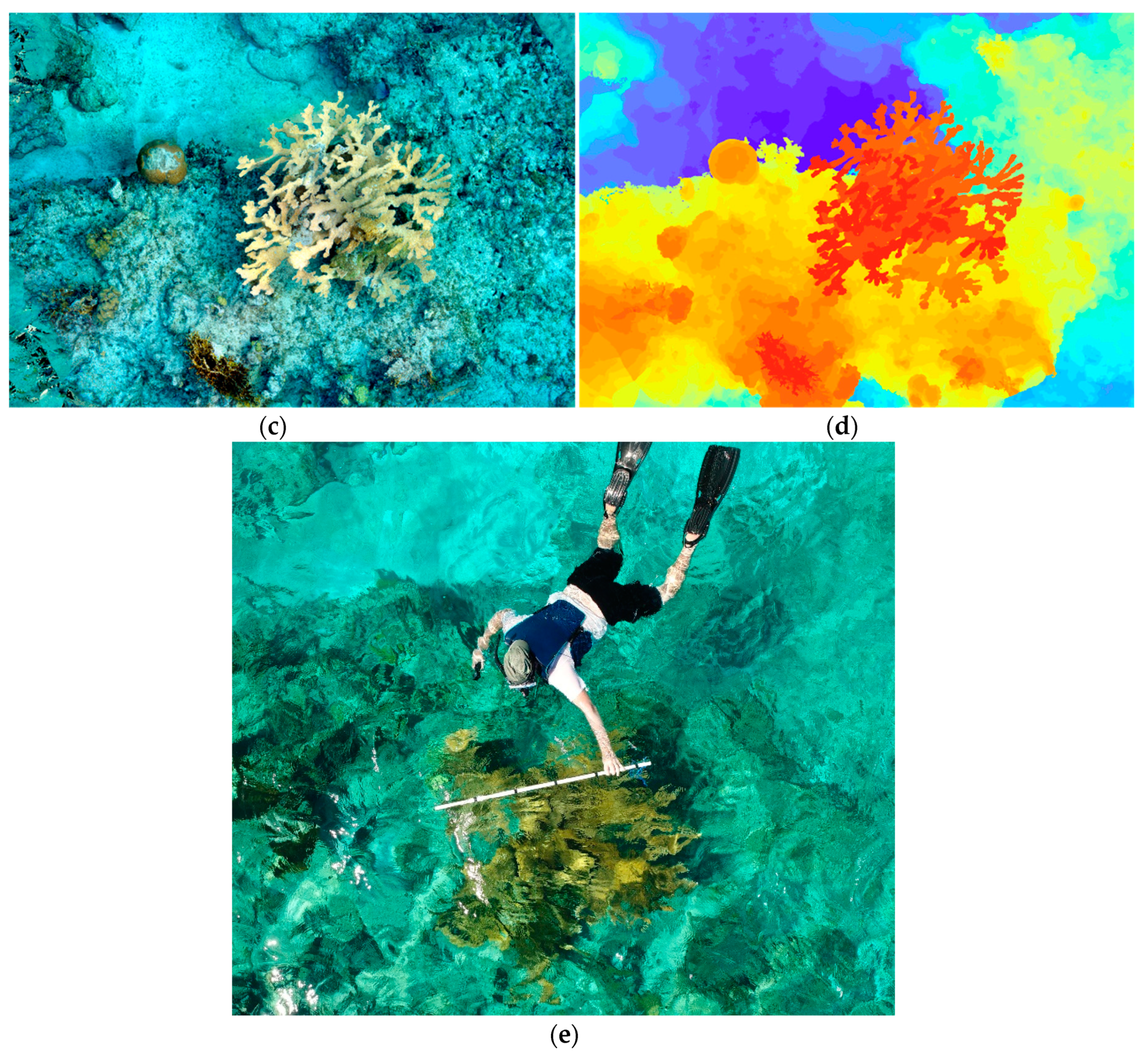
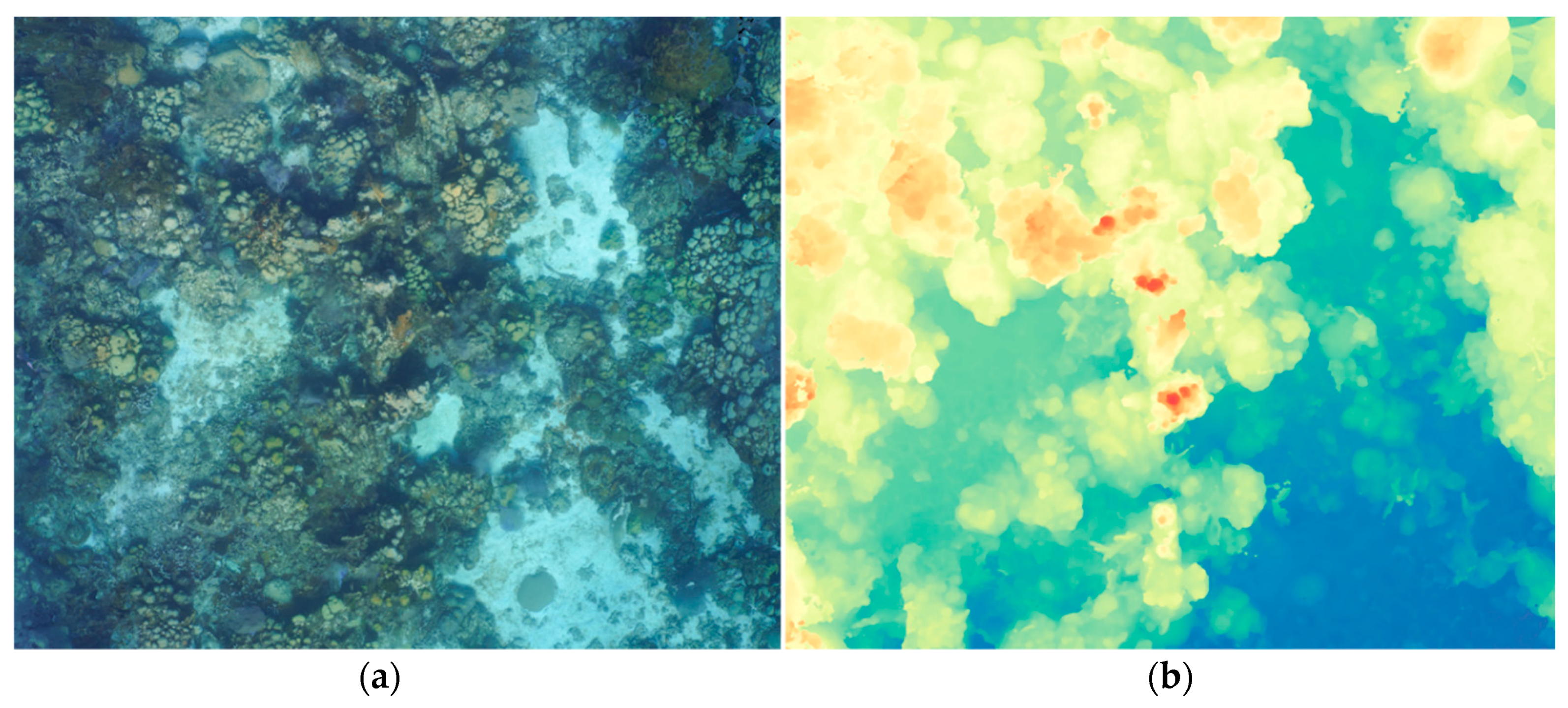
Recent storm damage was observed in the other two coral areas that were mapped. In Figure 9, a toppled Elkhorn Coral (Acropora palmata) can be seen as a result of the recent Category 1 Hurricane Beryl that had passed near the island a month prior. The average depth for these areas was slightly shallower (i.e., 3–6 m). The documentation of the damaged coral demonstrates the potential to utilize the Reef Rover to monitor changes in coral reef over time and study the impacts of other hazards, anchor damage, disease, bleaching, or other effects of climate change.

4. Discussion

Our results demonstrate that with current technology, a low-cost autonomous small unmanned surface vehicle (sUSV) can be designed and built to serve as an effective tool for collecting data and creating SfM models that can be used for mapping and monitoring coral reefs. Table 5 contains the results synopsis of the various configurations that were tested throughout our research. We present our lessons learned in the hope that this information will serve as an aide to others attempting similar designs and research for mapping coral reefs.
Our research efforts identified several challenges and corresponding solutions to achieving our goal of creating SfM models of coral reef environments utilizing an automated sUSV. Challenges included obtaining quality images in an environment of low light, sun refraction through the water column, salt water corrosion of the electronics, and the cameras overheating from continuous operation within a contained housing. We learned it was important to have a camera capable of a fast shutter speed (e.g., at least 1/800th/s) set to shutter priority with a frame rate of at least 3 frames/s to capture enough overlap between images. Ideal environmental conditions for operating the vehicle included low sun angle or overcast skies to minimize the sun fraction in the water column, and calm surface water with minimal currents.
The Reef Rover does differ in relation to other diver-based studies where illumination is often closer to the reef surface. Equipping the Reef Rover with a more powerful illumination source (e.g., electronic flash) may provide the needed image clarity and detail in the action cameras that were used; however, illumination from the surface >7 m may not result in improving image quality.
A primary challenge that was not adequately addressed in our research was the accurate geotagging of the images due to a less accurate GPS. This is an important area of future research that would enable conducting comparisons of more geometrically aligned SfM models over time. We found that the GPS that we utilized was not sufficient quality for mapping a relatively small area (<50 m2), resulting in a coordinate error that was much larger than the typical distance between real world camera locations (~1–3 m vs. <1 m). Rather, this error confounded the computation of the SfM keypoints, producing no results. In the future, a higher accuracy GPS is needed to record more precise locations and/or ground control points should be clearly established within the mapping area [24,28].
Despite these challenges, many technological advancements look promising for future development of unmanned automated surface vehicles and the monitoring products they will provide. These include increased computing power, longer battery capacity, more sensitive camera sensors, higher GPS precision (e.g., Differential GPS), advanced machine learning and classification techniques [29] on SfM products, and cloud processing of big data [25]. These advances will provide a greater ability to map larger areas in a more consistent manner and permit resource managers to be able to monitor small changes in coral reef environments at an increased temporal scale [13]. Such products will fill an important niche in multi-scale monitoring that will permit time-sensitive adaptive management actions to be implemented.

Supplementary Materials

The following are available online at the location specified: Video S1: Reef Rover Version 2 under power and collecting images over a reef in West Bay Grand Cayman, https://youtu.be/VopgnuvPnRg. Video S2: A flythrough of the SfM generated using the same data and of the same region depicted in Figure 8, https://youtu.be/lVXzxUH7ogI.

Author Contributions

Conceptualization, G.T.R. and S.R.S.; methodology, G.T.R. and S.R.S.; software, G.T.R. and S.R.S.; validation, G.T.R. and S.R.S.; formal analysis, G.T.R. and S.R.S.; investigation, G.T.R. and S.R.S.; resources, S.R.S. and G.T.R.; data curation, G.T.R. and S.R.S.; writing—original draft preparation, G.T.R. and S.R.S.; writing—review and editing, S.R.S. and G.T.R.; visualization, G.T.R. and S.R.S.; supervision, S.R.S.; project administration, S.R.S.; funding acquisition, S.R.S. and G.T.R.

Funding

This research was funded by generous grants from the Dart Foundation and the Rodney Johnson and Katharine Ordway Stewardship Endowment (RJ KOSE).

Acknowledgments

The authors would like to acknowledge the Cayman Islands Department of Environment and Fundación Dominicana de Estudios Marinos, Inc. (FUNDEMAR) for locating the test sites and field logistics support. We would also like to thank Jordan Mitchell for his contributions in helping us understand and utilize much of the technology presented in this article.

Conflicts of Interest

The authors declare no conflict of interest.

References

  1. Hedley, J.; Roelfsema, C.; Chollett, I.; Harborne, A.; Heron, S.; Weeks, S.; Skirving, W.; Strong, A.; Eakin, C.M.; Christensen, T.; et al. Remote sensing of coral reefs for monitoring and management: A review. Remote Sens. 2016, 8, 118. [Google Scholar]
  2. Flower, J.; Ortiz, J.C.; Chollett, I.; Abdullah, S.; Castro-Sanguino, C.; Hock, K.; Lam, V.; Mumby, P.J. Interpreting coral reef monitoring data: A guide for improved management decisions. Ecol. Indic. 2017, 72, 848–869. [Google Scholar]
  3. Page, C.A.; Field, S.N.; Pollock, F.J.; Lamb, J.B.; Shedrawi, G.; Wilson, S.K. Assessing coral health and disease from digital photographs and in situ surveys. Environ. Monit. Assess. 2017, 189, 18. [Google Scholar] [PubMed]
  4. Hamylton, S.M. Mapping coral reef environments: A review of historical methods, recent advances and future opportunities. Prog. Phys. Geogr. 2017, 41, 803–833. [Google Scholar]
  5. Purkis, S.J. Remote sensing tropical coral reefs: The view from above. Annu. Rev. Mar. Sci. 2018, 10, 149–168. [Google Scholar]
  6. Collin, A.; Ramambason, C.; Pastol, Y.; Casella, E.; Rovere, A.; Thiault, L.; Espiau, B.; Siu, G.; Lerouvreur, F.; Nakamura, N.; et al. Very high resolution mapping of coral reef state using airborne bathymetric LiDAR surface-intensity and drone imagery. Int. J. Remote Sens. 2018, 39, 5676–5688. [Google Scholar]
  7. Che Hasan, R.; Ierodiaconou, D.; Laurenson, L.; Schimel, A. Integrating multibeam backscatter angular response, mosaic and bathymetry data for benthic habitat mapping. PLoS ONE 2014, 9, e97339. [Google Scholar] [CrossRef]
  8. Porskamp, P.; Rattray, A.; Young, M.; Ierodiaconou, D. Multiscale and hierarchical classification for benthic habitat mapping. Geosciences 2018, 8, 119. [Google Scholar] [CrossRef]
  9. Burns, J.; Delparte, D.; Gates, R.; Takabayashi, M. Integrating structure-from-motion photogrammetry with geospatial software as a novel technique for quantifying 3D ecological characteristics of coral reefs. PeerJ 2015, 3, e1077. [Google Scholar] [CrossRef]
  10. Casella, E.; Collin, A.; Harris, D.; Ferse, S.; Bejarano, S.; Parravicini, V.; Hench, J.L.; Rovere, A. Mapping coral reefs using consumer-grade drones and structure from motion photogrammetry techniques. Coral Reefs 2017, 36, 236–275. [Google Scholar] [CrossRef]
  11. Palma, M.; Rivas Casado, M.; Pantaleo, U.; Cerrano, C. High resolution orthomosaics of African coral reefs: A tool for wide-scale benthic monitoring. Remote Sens. 2017, 9, 705. [Google Scholar]
  12. Teague, J.; Scott, T.B. Underwater photogrammetry and 3D reconstruction of submerged objects in shallow environments by ROV and underwater GPS. J. Mar. Sci. Res. Technol. 2017, 1, 5. [Google Scholar]
  13. Joyce, K.E.; Duce, S.; Leahy, S.M.; Leon, J.; Maier, S.W. Principles and practice of acquiring drone-based image data in marine environments. Mar. Freshw. Res. 2018. [Google Scholar] [CrossRef]
  14. Palma, M.; Pavoni, G.; Pantaleo, U.; Rivas, C.M.; Torsani, F.; Pica, D.; Benelli, F.; Nair, T.; Coletti, A.; Dellepiane, M.; et al. Effective SfM-based methods supporting coralligenous bethic community assessments and monitoring. In Proceedings of the 3rd Mediterranean Symposium on the conservation of Coralligenous & Other Calcareous Bio-Concretions, Antalya, Turkey, 15–16 January 2018; p. 94. [Google Scholar]
  15. Bayley, D.T.; Mogg, A.O. Chapter 6—New advances in benthic monitoring technology and methodology. In World Seas: An Environmental Evaluation, 2nd ed.; Sheppard, C., Ed.; Academic Press: London, UK, 2019; pp. 121–132. [Google Scholar]
  16. Fryer, J.G. A simple system for photogrammetric mapping in shallow water. Photogramm. Rec. 1983, 11, 203–208. [Google Scholar]
  17. Figueira, W.; Ferrari, R.; Weatherby, E.; Porter, A.; Hawes, S.; Byrne, M. Accuracy and precision of habitat structural complexity metrics derived from underwater photogrammetry. Remote Sens. 2015, 7, 16883–16900. [Google Scholar]
  18. Storlazzi, C.D.; Dartnell, P.; Hatcher, G.A.; Gibbs, A.E. End of the chain? Rugosity and fine-scale bathymetry from existing underwater digital imagery using structure-from-motion (SfM) technology. Coral Reefs 2016, 35, 889–894. [Google Scholar]
  19. Anelli, M.; Julitta, T.; Fallati, L.; Galli, P.; Rossini, M.; Colombo, R. Towards new applications of underwater photogrammetry for investigating coral reef morphology and habitat complexity in the Myeik Archipelago, Myanmar. Geocarto Int. 2017, 32, 1–14. [Google Scholar] [CrossRef]
  20. Ferrari, R.; Figueira, W.F.; Pratchett, M.S.; Boube, T.; Adam, A.; Kobelkowsky-Vidrio, T.; Doo, S.; Atwood, T.; Byrne, M. 3D photogrammetry quantifies growth and external erosion of individual coral colonies and skeletons. Sci. Rep. 2017, 7, 16737. [Google Scholar]
  21. Palma, M.; Rivas Casado, M.; Pantaleo, U.; Pavoni, G.; Pica, D.; Cerrano, C. Sfm-based method to assess gorgonian forests (paramuricea clavata (cnidaria, octocorallia)). Remote Sens. 2018, 10, 1154. [Google Scholar]
  22. Young, G.C.; Dey, S.; Rogers, A.D.; Exton, D. Cost and time-effective method for multi-scale measures of rugosity, fractal dimension, and vector dispersion from coral reef 3D models. PLoS ONE 2017, 12, e0175341. [Google Scholar] [CrossRef]
  23. House, J.E.; Brambilla, V.; Bidaut, L.M.; Christie, A.P.; Pizarro, O.; Madin, J.S.; Dornelas, M. Moving to 3D: relationships between coral planar area, surface area and volume. PeerJ 2018, 6, e4280. [Google Scholar] [CrossRef]
  24. Fukunaga, A.; Burns, J.H.; Craig, B.K.; Kosaki, R.K. Integrating three-dimensional benthic habitat characterization techniques into ecological monitoring of coral reefs. J. Mar. Sci. Eng. 2019, 7, 27. [Google Scholar]
  25. Johnston, D.W. Unoccupied aircraft systems in marine science and conservation. Annu. Rev. Mar. Sci. 2019, 11, 439–463. [Google Scholar]
  26. Chirayath, V.; Earle, S.A. Drones that see through waves—Preliminary results from airborne fluid lensing for centimetre-scale aquatic conservation. Aquat. Conserv. Mar. Freshw. Ecosyst. 2016, 26, 237–250. [Google Scholar] [CrossRef]
  27. Ventura, D.; Bonifazi, A.; Gravina, M.; Belluscio, A.; Ardizzone, G. Mapping and classification of ecologically sensitive marine habitats using unmanned aerial vehicle (UAV) imagery and object-based image analysis (OBIA). Remote Sens. 2018, 10, 1331. [Google Scholar]
  28. Neyer, F.; Nocerino, E.; Gruen, A. Monitoring coral growth—The dichotomy between underwater photogrammetry and geodetic control network. Int. Arch. Photogramm. Remote Sens. Spat. Inf. Sci. 2018, 42, 2. [Google Scholar]
  29. Ventura, D.; Bruno, M.; Lasinio, G.J.; Belluscio, A.; Ardizzone, G. A low-cost drone based application for identifying and mapping of coastal fish nursery grounds.Estuarine. Coast. Shelf Sci. 2016, 171, 85–98. [Google Scholar]
Figure 1. The Reef Rover Version 1 being deployed near a coral reef at West Bay, Grand Cayman. The electronic components inside the Pelican case are highlighted in the inset image in the upper left of the figure. The camera is mounted inside the case using a tripod mount and faces downward looking through a clear acrylic glass panel (upper right inset).
Drones 03 00038 g001
Figure 2. Fully assembled Reef Rover Version 2. The control unit is housed in the blue case and contains the autopilot, electronic speed controllers, radios, and Global Positioning System (GPS). The orange case contains the LiPo batteries that provide power to the control unit and electric motors. The following components are labelled in the lower image and detailed further in Table 1. (a) Blue Robotics electronic speed controllers (ESCs), (b) Blue Robotics T100 thrusters, (c) Pixhawk 1 flight controller, (d) Telemetry radio, (e) Radio and receiver for communicating with the remote controller (f) Ublox M8N GPS, (g) Waterproof panel plugs, and (h) 3 cell (11.1 volt), 5000 mAh LiPo batteries.
Drones 03 00038 g002
Figure 3. Reef Rover Version 2 showing two different camera systems. The upper right image shows the assembled system collecting data at the West Bay, Grand Cayman study site. The upper left image shows the system setup using four GoPro™ Hero 6 Black cameras. The lower images show the system setup using two Sony a6300 mirrorless cameras in underwater housings.
Drones 03 00038 g003
Figure 4. (a) A simplified rendering of a waypoint mission. The dimensions of actual Reef Rover missions we tested are described later in the text. The green points are the waypoints that define the desired mission path. The orange icon represents the vehicle and the trailing line is the actual path taken to complete the mission. (b) Using the default parameters, Version 1 overshoots turns and takes a long time to correct to the desired path (shown in orange). Note the large gaps between orange lines on Track 5 to 6 and 7 to 8, while in other areas, the orange lines are closer to the planned lines. (c) In addition to adjusting parameters, additional points are added along the track to follow the pre-defined mission lines more accurately. Version 2 allowed the vehicle to travel faster, thus better maintaining course lines (not shown), although the influence of ocean current drift remains an issue. (d) To address this problem, a double-grid mission over the area (in perpendicular directions) is used.
Drones 03 00038 g004
Figure 5. Reference maps showing the locations where Reef Rover data were collected. (a) Version 1 of the Reef Rover was tested at West Bay in Grand Cayman over coral reefs at the location indicated on the map; (b) Version 2 was tested in that same location in Grand Cayman as well as another location on the northeastern side of Catalina Island, Dominican Republic.
Drones 03 00038 g005
Figure 6. Several renderings of a Structure from Motion (SfM) model created using Reef Rover Version 1 centered over an Elkhorn Coral (Acropora palmata) colony located in West Bay, Grand Cayman with an average depth of 2–4 m. (a) The dense point cloud visualized from an angle. (b) The 3-D mesh from the same angle. (c) The 2-D orthophoto mosaic. (d) Rendering of the digital surface model (DSM). (e) Taking measurements of the corresponding coral head with a 150 cm PVC pipe marked with 30 cm increments and photographed from an aerial UAV.
Drones 03 00038 g006aDrones 03 00038 g006b
Figure 7. An example of the SfM outputs from the May 2018 data collection near Catalina Island, Dominican Republic with an average depth of 5–8 m. (a) an overview of the entire orthophoto mosaic generated from the input images. The area mapped and presented in this figure is approximately 15 × 20 m. The box represents the area presented in (b) and (c) the digital surface model (DSM), which is approximately 5 × 8 m.
Drones 03 00038 g007
Figure 8. An example of SfM outputs from the August 2018 data collection near Catalina Island, Dominican Republic of an area dominated by Boulder Star Coral (Orbicella annularis) and Pillar Coral (Dendrogyra cylindricus) with an average depth of 5–8 m. (a) the orthophoto mosaic and (b) the digital surface model (DSM). Supplement #S2 is a video flythrough of the same area. The total size of this area is approximately 15 × 15 m.
Drones 03 00038 g008
Figure 9. SfM outputs from the August 2018 data collection near Catalina Island, Dominican Republic in an area with multiple Elkhorn Coral (Acropora palmata) heads and an average depth of 3–6 m. The coral head in the lower right of the image is overturned and partially broken because of the recent Category 1 Hurricane Beryl. This area represents approximately 15 × 8 m in dimension.
Drones 03 00038 g009
Table 1. A cost summary of all the components used in Reef Rover Version 2.
ComponentCost per Unit in USD (Quantity)
4 m aluminum strips (24 × 8 mm)$48
8 mm stainless steel bolts and wingnuts$2 (8)
Foam body board$20
2 small Pelican cases (1120 and 1150)$80 (2)
Blue Robotics electronic speed controller (ESC)$25 (2)
Blue Robotics T100 thruster and mounts$120 (2)
Pixhawk 1 flight controller$100
Telemetry radio set$50
Radio and receiver set$150
Ublox M8N GPS$50
Waterproof panel plugs$8 (4)
3 cell (11.1 Volt), 5000 mAh LiPo batteries$40 (4)
Misc. electronic parts (e.g., wiring solder)$50
Sony a6300 with 16–50 mm lens$1000 (2 were eventually used)
Meikon underwater camera housing $150 (2)
Table 2. Summaries of the camera systems tested in Reef Rover Version 1 (a) and Reef Rover Version 2 (Figure 3) (b).
(a)
Camera TypeDescription of System
YI™ 88001 Action Camera (16MP)
2.73 mm fisheye lens (155° field of view (FOV))
(Xiaoyi Technology co., Ltd., Shanghai, China)
1 camera center mounted inside a single Pelican case along with all other electronic components
Sony a6000* with 16–50 mm f/3.5–5.6 Lens (24MP) (Sony Corporation, Minato, Tokyo, Japan)1 camera center mounted inside a single Pelican case along with all other electronic components
(b)
GoPro™ Hero 6 Black (12MP)
2.92 mm fisheye lens (149° FOV)
(Woodman Labs, Inc., San Mateo, CA, USA)
4 cameras mounted across aluminum frame
20 cm below the water surface
Sony a6300* with 16–50 mm f/3.5–5.6 Lens (24MP) inside Meikon waterproof housing 2 cameras mounted across aluminum frame
15 cm below the water surface
* Both Sony camera models have identical sensor and lens mount (Sony E-mount). The primary difference is the a6300 model can acquire multiple images per second, while the fastest interval the a6000 can achieve is about one photo every 1.5 s. Images collected for all mapping missions were with the lens set to 16 mm.
Table 3. Autopilot parameters modified to facilitate the execution of a planned mapping mission. The settings listed in parentheses were identified as optimal for Version 2.
ParameterDefinitionSetting
CRUISE_SPEEDThe target speed for the vehicle while executing an autonomous mission.1 or 2 m/s
(3 m/s)
CRUISE_THROTTLEThe base throttle percentage to use in auto mode (adjusted by the autopilot).50% (80%)
WP_RADIUSThe distance in metes between the rover’s current GPS position and the waypoint it is traveling to when it will be considered to be reached by the autopilot. This determines when the rover will turn to the next waypoint on the path after the current waypoint.2 m (1 m)
PIVOT_TURN_ANGLENavigation angle threshold in degrees to switch to pivot steering. This allows you to set up a skid steering rover to turn on the spot in auto mode when the angle it needs to turn is greater than this angle. An angle of zero means to disable pivot turning. Note that a lower value for WP_RADIUS will execute smoother turns.180° (45°)
Table 4. The size of the Sony a6300 camera (set at 16 mm) footprint calculated for given depths in both the narrower and wider dimensions. The required minimum distance between survey lines is also given for a desired 70% overlap. All units are in meters except ground sample distance (GSD), which are listed in mm.
Footprint DimensionsRequired Min. Distance
DepthImage LengthImage WidthFor Survey Lines (70% Overlap)GSD (mm)
11.01.50.40.3
32.94.41.30.7
54.97.42.21.2
109.814.84.42.5
Table 5. Summary of Reef Rover configurations and resulting SfM models generated.
VersionCameraResultComments
1Yi Action Camera
(1)
SfM failed to renderImages acquired from a single camera were not sufficient quality to generate keypoints due to image blur, surface disturbance, and shallow depth. Overlap was an issue because of slower shutter interval (1.5/s).
2GoPro Hero 6 Action Camera
(4)
SfM failed to renderDespite utilizing 4 simultaneous cameras at a faster shutter (1/s) the image quality was not sufficient to render an SfM model regardless of input parameter tuning. Potential positive results would include the use of a flash to increase image clarity and detail.
1Sony a6000
(1)
A single area was successfully modeled with manual intervention (Figure 6)Images acquired from a single camera at a shutter interval of 1.5/s were high quality, but did not achieve sufficient overlap required for SfM, particularly in shallow areas. Success was achieved with manual intervention to fill overlap gaps.
2Sony a6300
(2)
Several successful SfM models were generated for areas greater than 30 × 30 m (Figure 7, Figure 8 and Figure 9)The faster shutter interval (3/s) tested in a slightly deeper area (>3 m) allowed the vehicle to collect quality images that were successfully used to generate SfM models.

