1. Introduction
The world’s population is increasing rapidly, which in turn leads to an increase in the demand for basic necessities. Among such needs, health and security are the most critical. Therefore, even a short period can be a decisive moment between life and death in areas deprived of these facilities. Rapid medical response teams using the ground vehicles are, usually, deployed in distributed manners for timely supply of aid to persons in affected areas. However, this is not an easy task in remote places [
1,
2] due to the possibility of challenging terrains and dense populations. The time taken by the team to reach the field depends on multiple factors and may vary, which is not affordable in emergencies. The recent growth of drone technology could be used as an alternative for this purpose. Aerial transport can provide aid to places where direct and rapid help are otherwise not possible. Aerial support is efficient in the sense that it does not depend on the hurdles in the path, e.g., traffic jams and damaged roads. Such systems are developed with multiple functionalities to monitor, analyze, and respond to complex situations. Recent advancements in technology have enabled the integration of more and more computing resources on a single chip to accommodate the demand of multiple functionalities in an autonomous system [
3].
In this paper, we focus on the development and evaluation process of a rapid response unit based on a quadcopter. The project aims to minimize the response time for providing necessary medicines to an emergency spot. It is intended to gain access and provide timely help in areas that are inaccessible using ground vehicles. The rapid response system is designed for helping a specified field person working in the affected areas. The field person could be a tourist in a safari park or a farmer working in the field. The quadcopter approaches him/her with first aid, i.e., necessary medicines. The system consists of two parts: an electronic system carried by the field personnel in the area and a quadcopter-based response unit at the base station. The medical condition of the field person is monitored with the help of a sensor-based electronics system. The observed medical parameters include temperature and heartbeat. In the case of an emergency, an interrupt is generated, and the location of the field person accessed through GPS is transmitted through the GSM communication system to the base station. The staff monitoring this information at the base station passes on the received location (longitude and latitude) to the software running in the control room of the base station; eventually, the quadcopter itself flies to the guided point with the medical aid. After providing the supply of aid to the supervised area, it returns to the launch point automatically without any user input. Throughout the entire flight, as in the manual mode, a continuous feed is provided in the autonomous mode to the Virtual Reality (VR) goggles supported by a smartphone [
4].
An additional feature of the system is an Inertial Measurement Unit (IMU) sensor embedded on top of the VR system that allows the user to tilt and pan the camera gimbal with his/her head movement. Another mode of operation is provided where the field person calls the drone by pushing a button and initiating a distress call through the equipped gadget. The camera movement is synchronized with the head movement of the staff monitoring the operation at the base station. Hence, the quadcopter’s camera becomes his/her eyes.
The main contributions of this work are as follows:
A quadcopter-based efficient aerial aid system is developed to eliminate the delay time for the first aid supplies system in densely-populated and remote areas.
An electronic system for observing the bio-medical parameters including pulse rate and body temperature of the field person is designed.
A system for live remote monitoring of the aerial path and event place is developed.
An IR-based obstacle-evasion model to replicate the working of the autonomous collision-avoidance system is developed.
The rest of the article is organized as follows.
Section 2 presents related work.
Section 3 describes the methodology.
Section 4 discusses the results. Concluding remarks are outlined in
Section 5.
2. Related Work
The use of Unmanned Arial Vehicles (UAVs), drones, etc., may be classified by their applications to the military environment, commercial purposes, or research work. In the past decade, modern warfare has employed UAVs for targeted assassination in the war against terror. Especially, the U.S. military introduced drones [
5] as a source for the unmanned wirelessly-controlled mode of transport for point-to-point operation where GPS is the foundation of this entire operation.
In the last five years, the rising awareness of humanitarian drones in the public has led to a drastic increase in their employment in specific major departments including surveillance, agriculture, product delivery, etc. [
6,
7]. With the advent of this innovative field of control and automation, various multi-national companies are now investing their capital at large scales to patent their commercial models. These companies include HUBSAN, SECOM, MATTERNET, etc. DJI is one of the major leaders in this field. According to their president Luo Zhenhua, DJI accounts for over 70% of the commercial and civilian drone market [
8]. Being manufacturers, they offer drone models dedicated to a particular field or application. For example, MATTERNET uses GPS along with some other sensors for navigation between the automatic control station to deliver medications in remote locations that have no direct route or insufficient roads [
9]. For example, MATTERNET supplied medical aid in New Guinea and Switzerland [
10], as well as in Haiti after a severe earthquake in 2010 [
5]. The corporation works with the well-known organization “UNICEF” and “Doctors Without Borders”. Alternatively, the DJI’s Inspire 2 is capable of high standard aerial filming and surveillance. The system supports the upgraded transmission of video with a dual signal frequency and channel that stream video from the main, as well as from an onboard camera simultaneously [
11]. Released on 28 January 2018, DJI’s Mavic Air uses advanced Visual Inertial Odometry (VIO) technology, a very effective sensing mechanism in FlightAutonomy 2.0 comprised of a main gimbal camera with dual-vision sensors with backward, forward, and downward direction movement, IMU redundancies, and a set of cores for computation [
12]. They transmit to the powerful processors and collect data from the local environment for better flight performance and accurate hovering. In addition to dual IMUs, FlightAutonomy 2.0 increases the flight safety level through the addition of some redundant modules.
Similarly, DHL has worked on the usage of drones for the delivery of medical aid in Germany. They used three generations of medical drones and called it Parcelcopter [
13]. The first generation was able to move a distance of 1 km to deliver blood samples to a laboratory across the river at Bonn. They tested the second generation of drones for urgent delivery of medication and other necessary materials to Juist, one of Germany’s remote North Sea Islands, for almost three months [
14]. DHL tested the third generation Parcelcopter from January–March 2016, for delivery of necessary medicines and supporting material between automated skyports in two Bavarian Alpine villages. The drone only took 8 min instead of a 30-min road trip to the specified locations [
15]. Time is quite critical in medical emergencies. Moreover, it also reduces fuel consumption.
A drone-based prototype ambulance was tested to deliver defibrillators to cure sudden cardiac arrest in The Netherlands [
15]. The average drone speed was around 60 miles per hour, and it can reach the patients within a radius of 4.6 square miles with an average time of 60 s. The traditional ambulance takes around 10 min to reach the patient. The chances of survival of patients increased to 80% versus 8% for conventional emergency services. The process starts by tracking the patients call and following the GPS coordinates. The paramedic in control remains in contact using the live video from the camera on the drone to instruct and assist the patient or a person at the location. It may take another five years to develop the operational emergency drone network and to address the legal matters. The cost of the system is estimated at around
$19,000 for each drone [
16].
Along with these practical applications, extensive research work is being done in this field to craft different applications. For example, UAVs are now being employed as a spectrometer for land cover classification [
7]. Since a spectrometer measures the spectral signatures of energy into different wavelengths, the sensor’s field of view allows environment scanning by analyzing the spectral characteristics of light radiation. This system embedded on a UAV proves to be extremely helpful in land mapping, large-scale agriculture, open-pit mining [
17], etc. Similarly, due to the increased trend of a more compact physical structure, recent research has proven that UAVs can be used for surveillance in narrow spaces, which are very difficult for humans to reach. This application is demonstrated in a research project named the Assessment of Chimpanzee Nest Detectability in Drone-Acquired Images [
18]. They developed a mixed-effects logistic regression model for evaluating the impact of image resolution, seasonality, the height of the nest, and color on detection of the nest.
3. Methodology
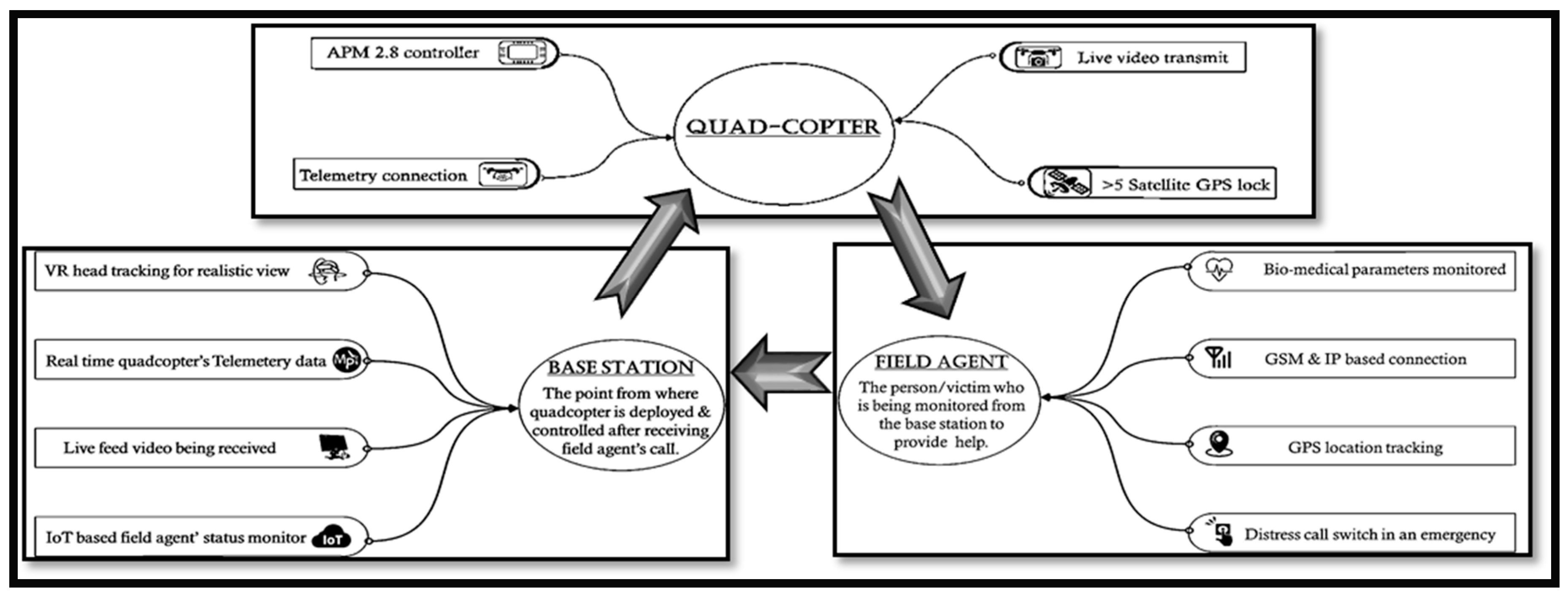
In this section, the working of the three sub-systems is explained sequentially as these systems interrelate with one another to accomplish the entire application. Initially, the steps of interfacing a quadcopter-based drone, together with its mathematical formulation, is described. This is followed by its hardware-based electronic setup, as well as software setup for its operation. Successively, the micro-controller-based embedded system for the field person and the working of VR head tracking are presented. Finally, an infra-red-based quadcopter obstacle avoidance prototype is demonstrated, which mimics the real-time concept of obstacle avoidance for UAVs.
Figure 1 shows the block diagram of these sub-systems and demonstrates their interrelation. The quadcopter starts its journey from the base station, travels to the field person, supplies the medicines, and returns back.
3.1. Multi-Rotor Dynamics
The force that is used to overcome the drag of an aircraft, as well as its weight due to gravity is termed thrust. In the case of multiple rotors, the thrust is the force that is orthogonal to the propellers [
19]. It is generated by rotation of the rotor at a certain velocity. Moreover, it accelerates the body in the direction of its force. The thrust
T is calculated using the parameters
v (velocity),
(air-density), and
A (cross-sectional area) of the propeller and is given in Equation (1).
In Equation (1),
i refers to the rotor of a particular axis. For takeoff, the cumulative thrust generated by the propellers must be greater than the gravitational pull due to the weight of the model. In the case of the quadcopter, the thrust is produced when the rotational direction of the opposite rotors is alike.
Equation (2) involves the summation of 4 rotational velocities. The equation specifies these rotational velocities for quadcopter since they also use 4 rotors for the flight. However, when the net thrust of all the rotors is equal to 0, the quadcopter maintains a constant altitude (↑ upward thrust, ↓ downward thrust), also known as hovering, and is provided in Equation (3).
3.1.1. Electronic Setup
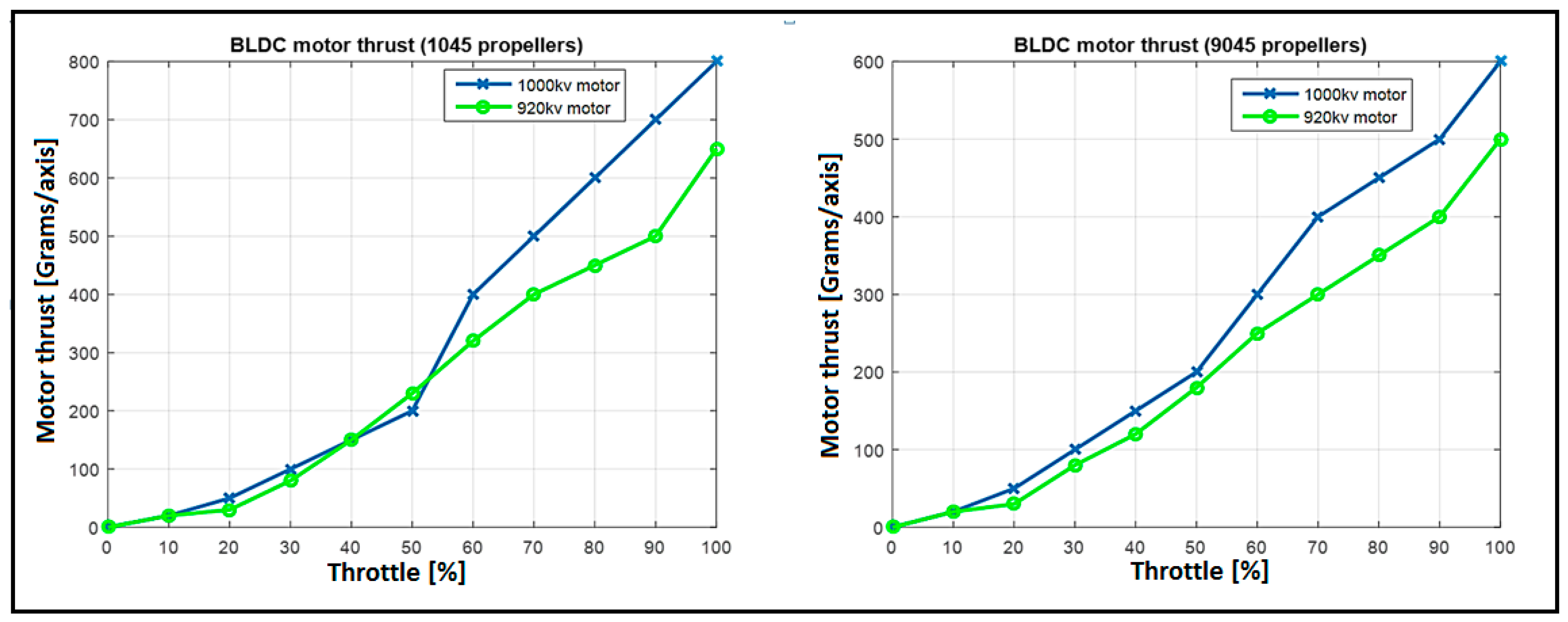
Rotors are an essential component of any quadcopter as they are the primary source to generate the required thrust. The required payload is approximately 500 g, and the design process is completed using Equation (4).
A = motor thrust = 700 g/axis
B = number of motors = 4
C = weight of the craft itself = approximately 1400 g
D = % hover throttle = 70%
Payload capacity = (A × B × D) − C = (700 × 4 × 0.7) − 1400 = approximately 560 g
As a result, 1000-KV brushless motors were selected for the quadcopter after an experimental analysis obtained on the basis of data logging, as shown in
Figure 2. A 35-amp Electronic Speed Controller (ESC) provided power, as well as PWM signals for the rotational speed variation to the motors. This signal was generated by the flight controller (APM-2.8 of ArduPilot company from China) from the input controlled by the user through the RC receiver. Along with it, a hook mechanism was applied by using an SG-90 (teyleclan company from China) servo motor for the payload dropping system. Using this mechanism, the quadcopter can autonomously release the attached supply after reaching the destination of its guided trajectory.
3.1.2. Software Setup
Mission Planner software was used as a core for setting up of the quadcopter’s software. Real-time statistical data of the model were monitored during the flight through the telemetry link. These data include the operational values of all the operating channels (
Table 1), power ratings, and GPS location.
Table 2 describes different flight modes along with the relevant PWM range and description.
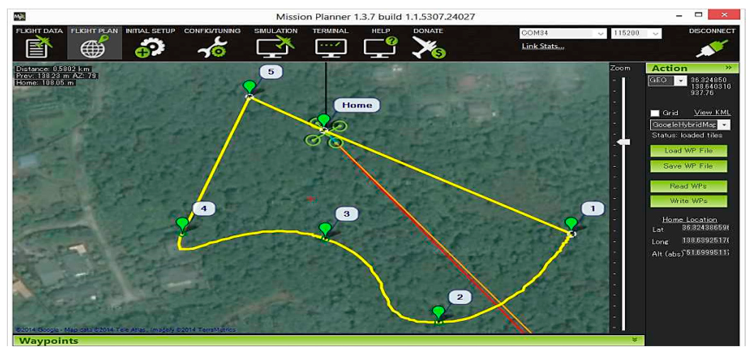
Figure 3 shows the trajectory of an autonomous flight. The trajectory is user defined and is programmed to the flight controller whose destination is marked by the coordinates received in the distress call. During the mission, the pilot’s roll, pitch, and throttle inputs are ignored, but the yaw can be overridden with the yaw stick of the radio transmitter. This allows the pilot to aim the front of the copter as the copter flies to the mission. After reaching the destination, the flight controller is programmed to unlock the servo motor’s payload hook automatically to release the first aid supply for the victim.
3.2. Embedded System for Distress Call
A modular system based on the GSM and IoT communication link is interfaced. This system sends an autonomous distress call to the base station if the bio-medical parameters (pulse rate and body temperature) exceed the normal range.
The designed embedded system is divided into 2 parts. The first part is a handheld system comprised of measuring sensors and a 433-MHz RF to transmit the measured values to the other part. The second part is the transmission kit, which receives data from the handheld system. After tagging it with location coordinates through a GPS module, it sends the data as a text message to a designated smartphone application via a GSM module.
3.3. Virtual Reality Head Tracking System
In the case of manual or un-guided auto-flights, an approximate waypoint radius is known instead of the exact destination. Therefore, virtual reality along with live video monitoring is applied in such a situation to pinpoint the emergency spot. In this process, a ts5828 wireless video transmitter mounted on the quadcopter receives the video signal from the camera and transmits it over a frequency channel of 5.8 GHz. The transmitter is paired with a wireless video receiver (RC-305 of Boscam company from China) at the base station before flight initiation. This video receiver is linked up with a smartphone, and the operator can receive a constant live feed of the quadcopter’s entire flight. The next step is the use of a VR headset along with the smartphone that is receiving the live feed. The headset is linked with an IMU interfaced to a micro-controller. It tracks the operator’s head movement and moves the camera mounted on the quadcopter. This creates a virtual environment as the operator feels a realistic search operation during the flight experience.
3.3.1. Degree of Freedom
The degree of freedom of a system is the number of independent parameters that define its configuration. A rigid body in space has a total of 6 DoF in a 3-dimensional space.
Equation (5) gives the Kutzbach formula [
20] to determine the DoF of a body.
F = Degree of Freedom (DoF)
n = number of links
j1 = number of lower pairs
j2 = number of 2 higher pairs
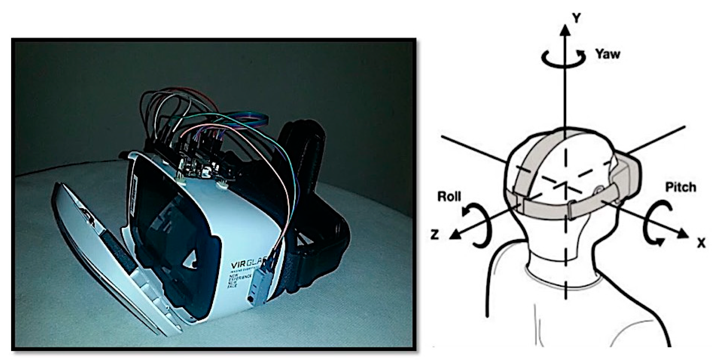
The IMU attached on the VR headset calculates the offsets of yaw and pitch movement of the head. These values are then wirelessly transmitted to the camera gimbals’ servo motor.
3.3.2. Inertial Measurement Unit Setup
The ATMega328P of Arduino from Italy controller IC after being interfaced with a 16-MHz clock crystal and electrolytic capacitor consequently supports the I2C communication protocol through the IO pin. The integrated system was connected to a computer through the Future Technology Devices International (FTDI) serial to USB converter. The MPU-6050 of Sparkfun from Hongkong was then interfaced with it on IC pins 27 and 28, i.e., SDA (serial data) and SCL(serial clock), respectively. The Arduino Integrated Development Environment (IDE) was used for the programming of this micro-controller. The C-program consisted of the following parts:
Receiving raw data from the IMU.
Rendering these data to judge the movement.
Encoding these data for pulse position modulation.
Transmitting data as a PPM signal though GPIO pin 7.
This compact system was then placed on top of the VR headset to have real-time head tracking, as shown in
Figure 4.
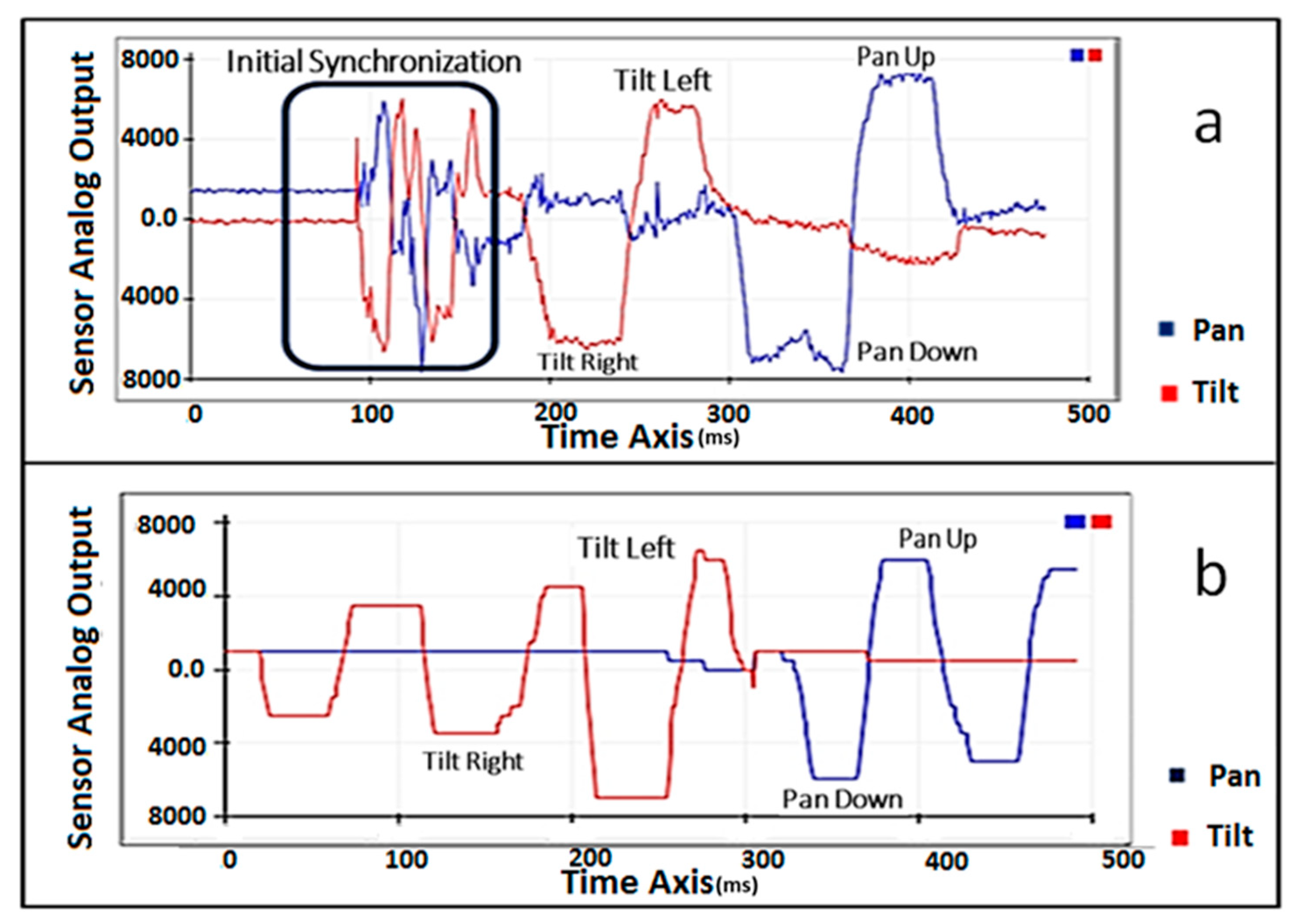
3.3.3. Signal Transmission Technique
The signal for wireless head tracking was transmitted through the radio transmitter to the camera gimbal (pan tilt mount). This signal comprises the calculated offsets of the head movement measured by the IMU attached to a micro-controller.
Figure 5a shows the raw data received from the IMU, while
Figure 5b shows the interpretable data collected after filtering that are to be transmitted.
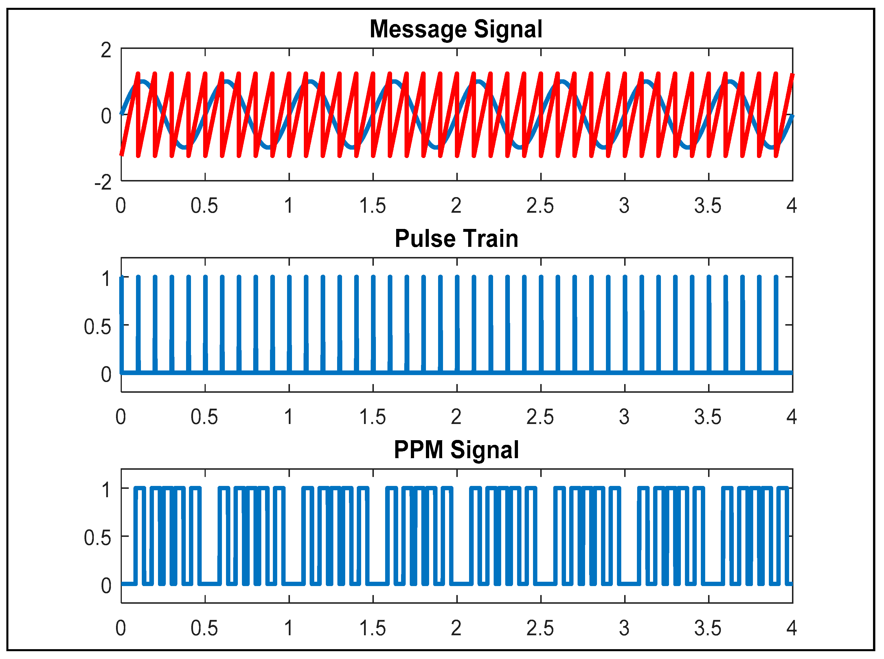
Since two signals (horizontal and vertical head movement) were to be multiplexed on a single wireless transmission channel, so the Pulse Position Modulation (PPM) technique was applied to achieve this task.
Figure 6 shows a PPM signal generated in MATLAB.
In this process, a periodic signal was divided into multiple pulses, which were equal to the total number of 8 channels of the radio receiver.
A complete PPM frame was set to 22.5 ms, and the signal low state was always 0.3 ms. It began with a start frame (high state for more than 2 ms) for initial synchronization. After that, each of the 8 channels was encoded by the time of the high state (PPM high state + 0.3 × (PPM low state) = servo PWM pulse width). This value of the high state of Channels 1–5 and 8 was transmitted directly from the radio transmitter, while for Channels 6 and 7 (pan and tilt camera gimbal attached, respectively), which were controlled by the IMU’s offsets, this was dynamically varied with the head movement by following a technique named trainer mode in Radio Control (RC) terminology.
The trainer mode, however, is primarily used to share the control of partial channels of the UAV’s receiver with another radio. This configuration was used to teach a co-pilot during flight. By following this phenomenon, the microcontroller’s signal, which was the IMU’s offsets, was taken as an input from the co-pilot’s controller for the sake of this research. Once the control transfer switch was triggered on the primary controller, the control of Channels 6 and 7 was transferred to the micro-controller.
3.4. Infra-Red-Based Obstacle Avoidance Model
3.4.1. Quadcopter steering
While steering a quadcopter, the pilot controls two input channels, i.e., pitch and roll. The to and fro motion used pitch input, while roll input was used for left and right movement. During the manual flight operation in which the pilot completely controls the quadcopter through the radio transmitter, specific PWM values were transited for each of the channels. The PWM values then directed the Electronic Speed Controllers (ESCs) to adjust the rotational speed of the rotors simultaneously, which consequently made it possible for the quadcopter to move.
3.4.2. Dynamic Proportional Scaling
For obstacle avoidance capability, dynamic proportional gains are to be scaled for the pitch (forward and backward movement) and roll (left and right movement) of the quadcopter. In the case of directional propagation of the quadcopter, the rotational speed of the rotor in that particular direction was reduced by a specific factor. The speed of the opposite rotors was increased proportionally, which allowed the motion of the quadcopter in the air.
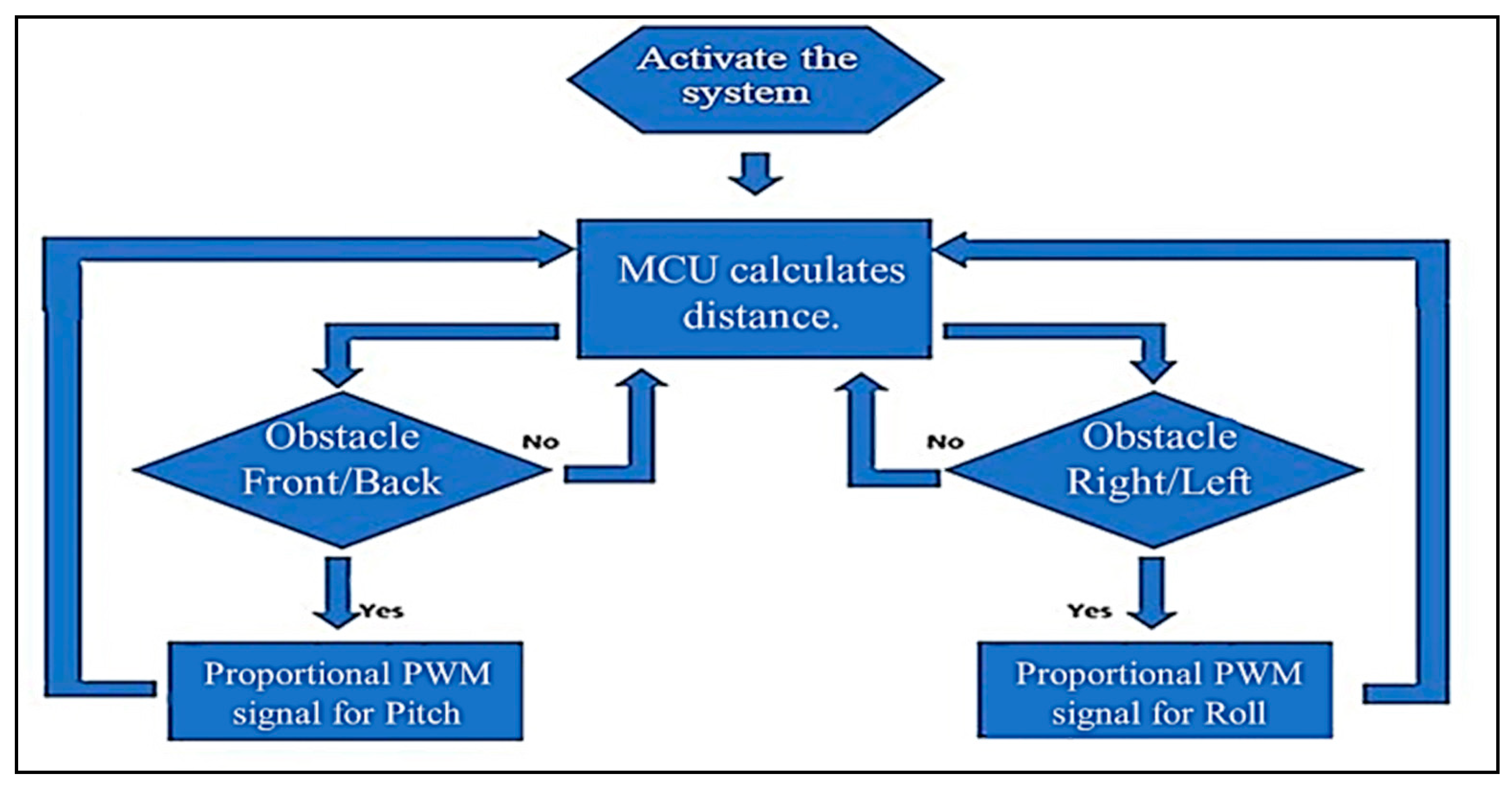
The reverse application of this phenomenon was therefore used to implement the autonomous obstacle avoidance system. If an obstacle were present in front of the quadcopter or any direction, then this reduction of the distance measured by the integrated infra-red sensor triggered the rotational speed increment of the rotor in that particular direction. The flowchart of
Figure 7 shows this working algorithm; according to it, after activation of the sensors, they continuously measure the distance and control the roll and pitch accordingly.
Through this, the quadcopter automatically tends to apply the brakes and start hovering instead of colliding with the obstacle.
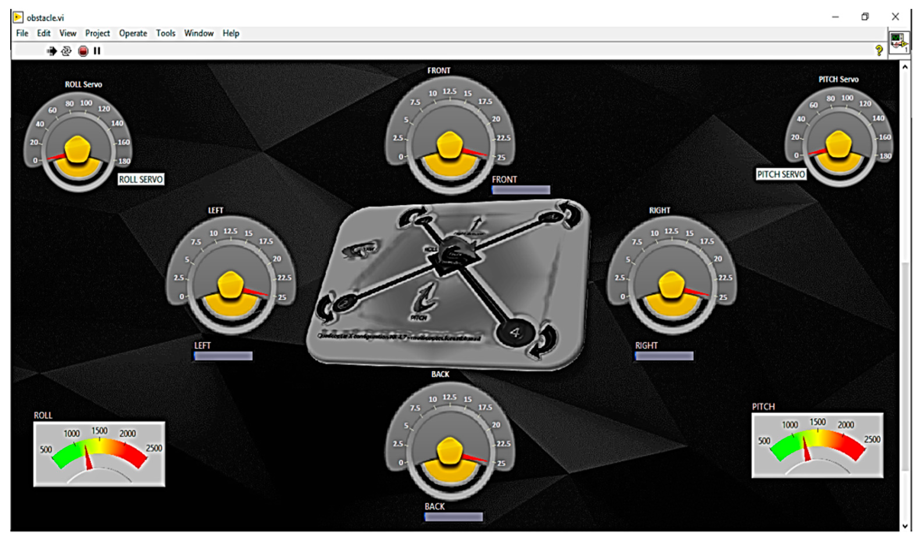
3.4.3. LabVIEW Modeling
LabVIEW software was used to demonstrate the working of the system with real-time data.
Figure 8 shows the designed front panel of the LabVIEW Virtual Instrument (VI). The MCU used for the model would interact with the sensors through this VI.
Initially, analog signals given by the sensors were used for calculating the distance from all four sides. By conditional statement blocks, a proportional gain was added to the PWM signal upon the occurrence of an obstacle. After this, two servo motors were initialized in the software by mentioning the GPIO pin to which they were attached. The modified PWM signal was given as input to the motors, which rotated their shafts in the according direction.
4. Results and Analysis
The final deliverable was a complete application-oriented aerial aid system offering assistance to multiple commercial and domestic users in the form of a rapid and autonomous delivery system for medical aid, as well as a reliable source of surveillance.
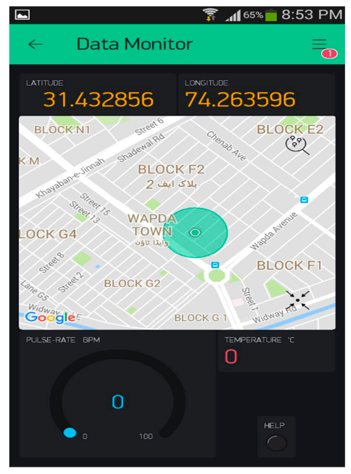
4.1. Android-Based IoT Link
After receiving data including the heart rate, body temperature, and GPS location from Arduino Mega through serial communication, the NodeMcu micro-controller had these values uploaded to it over the Internet to provide independent real-time global access of this data [
21]. For this purpose, an external server named Blynk was used [
22]. Blynk is an open source platform that provides the facility of remote data interaction to the developers of both IOS and Android. Along with a public server, Blynk also offers a smartphone-based Application Program Interface (API). This API was used as a development platform for accessing the data from the field person.
Figure 9 shows the final user interface of the designed application.
Each connection had a unique authentication code assigned to it. This code acted as a bridge between the smartphone app and the hardware. As soon as the API was triggered for received data, the paired device was checked for uploading data. If yes, the communication started. Similarly, after getting power, the hardware side (which was primarily based on NodeMcu) waited for the Wi-Fi connection with the SSID and password provided in the code. After this successful connection, NodeMcu started uploading the data to the open-source Blynk server according to the program’s logic over the same authentication code. Once the hardware was communicating with the app, links were established between the incoming data and the display fields. In other words, each of the incoming or outgoing data was assigned with a label (a virtual pin) in program code. Finally, the label was linked with a display field, which showed the real-time value of the data.
4.2. Practical Flight Performance
4.2.1. Autonomous Distress Call
Since the distress call was based on the values of biomedical parameters, a test flight was carried out to check the response of the complete system.
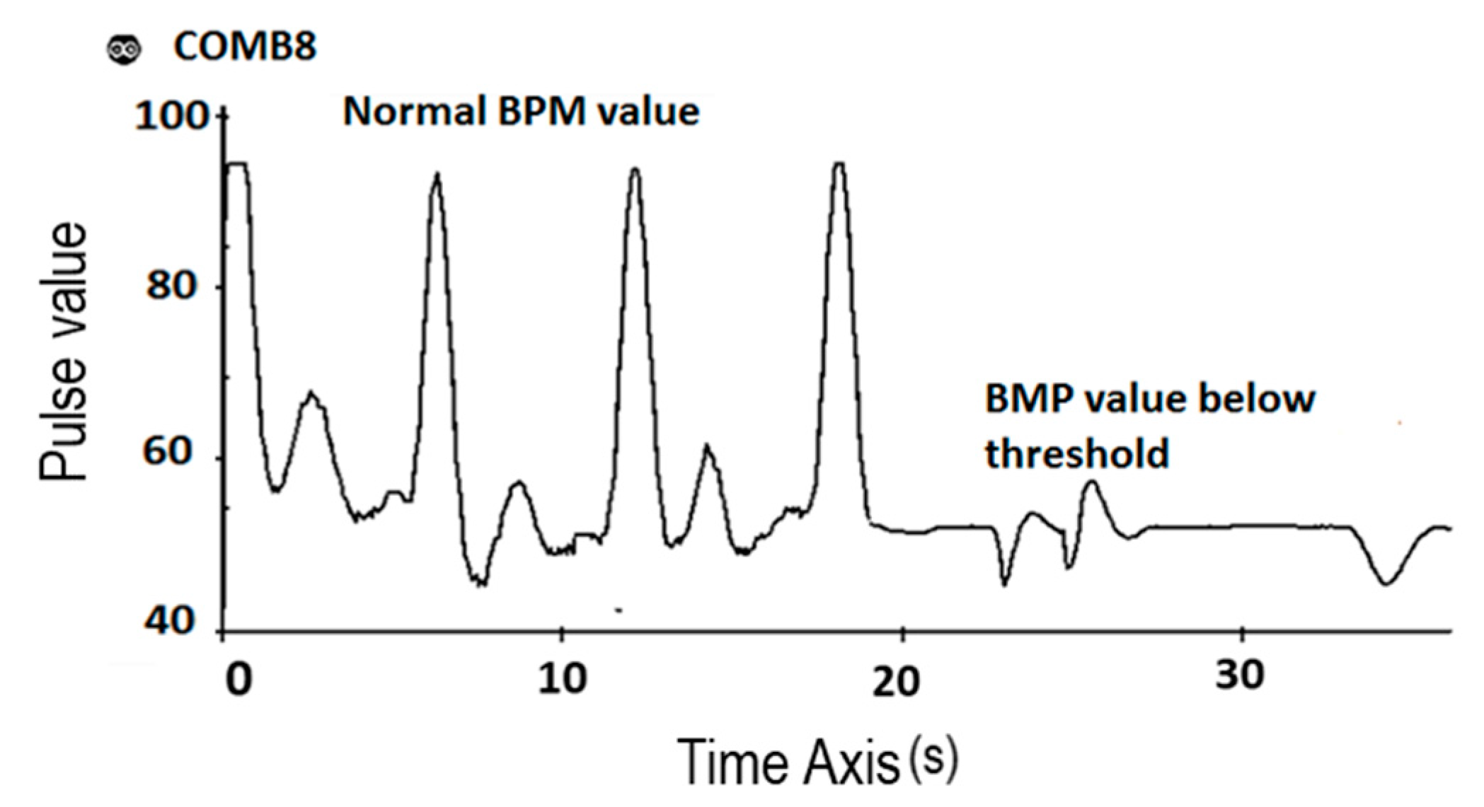
Figure 10 shows the falling trend in the pulse rate sensor’s data when the heartbeat falls. When the heartbeat value exceeded the lower limit of the preset normal range of the pulse rate, an autonomous distress call was initiated.
This call was sent on both communication channels as a text message via GSM, as well as to the Android application via the Internet.
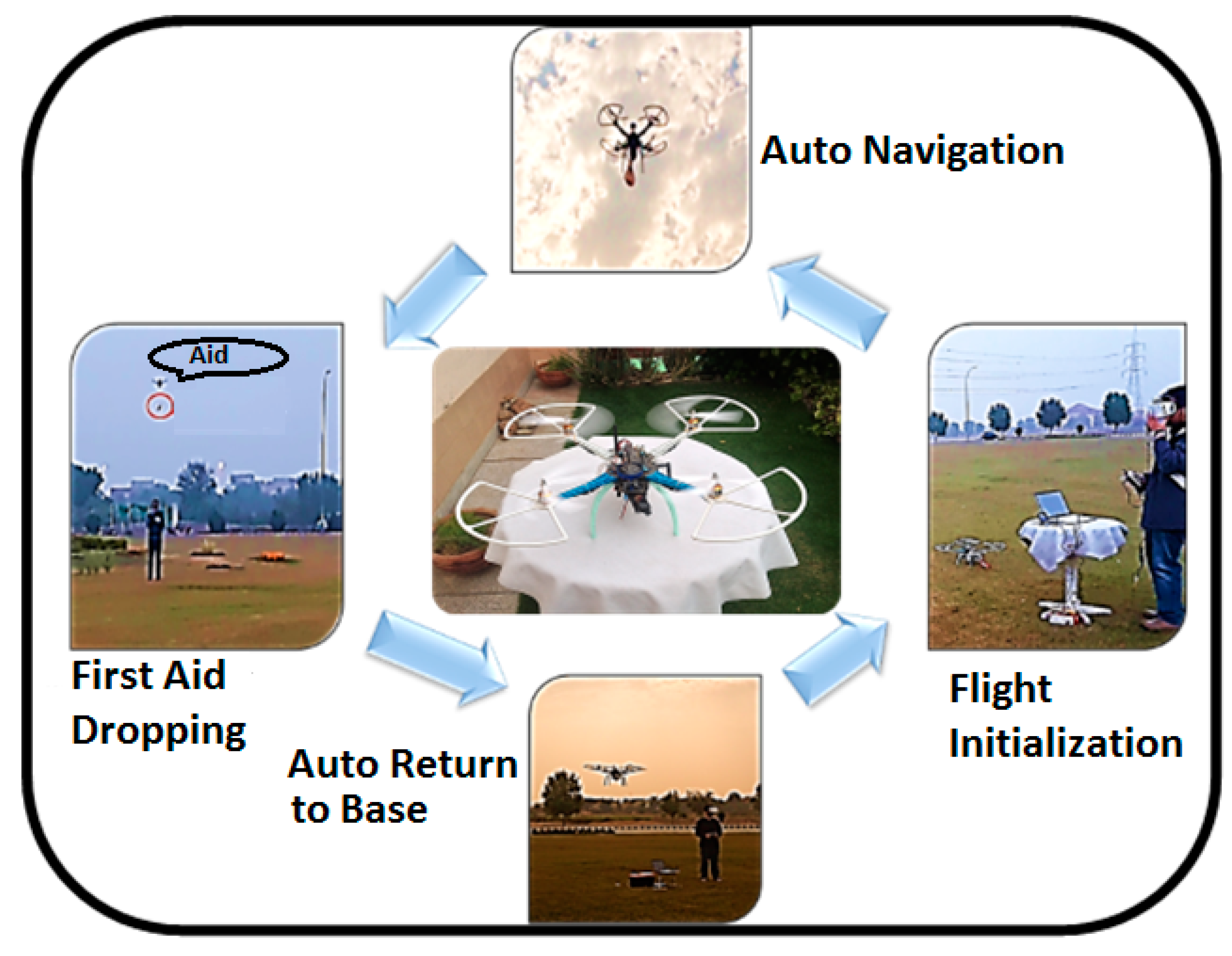
4.2.2. Mission Planning and Flight Initiation
The quadcopter was deployed from the base station after setting a trajectory for its autonomous flight. The destination point of the path was the GPS location received through the distress call.
Figure 11 shows the flight cycle, which started from initialization, auto-navigation, dropping the supply, and returning to the launch point automatically.
4.3. Obstacle Avoidance Specification
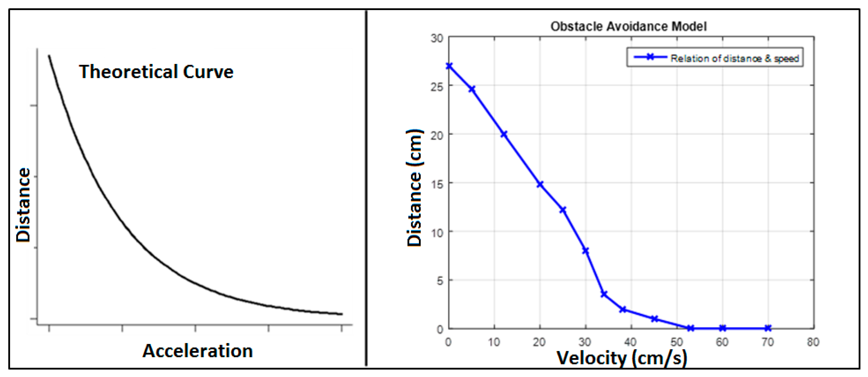
The performance of the obstacle avoidance model of the quadcopter was tested by exposing it to incoming obstacles at various speeds. Theoretically, it was found that the response time should be directly proportional to the speed of the vehicle. In other words, the drone flying at relatively low velocity would sense the obstacle sharply and at a relatively greater distance.
Table 3 shows the experimental results for the model performance. In this test, the distance at which the model outputs the propositionally-gained PWM value to the servo motors was set as the point of obstacle detection.
After the testing process, a comparison was made between the theoretical and the experimental values by the help of the MATLAB plot. The first part of
Figure 12 shows the theoretical graph and the second part the experimental MATLAB plot. The results showed that the experimental results followed the theoretical trend.
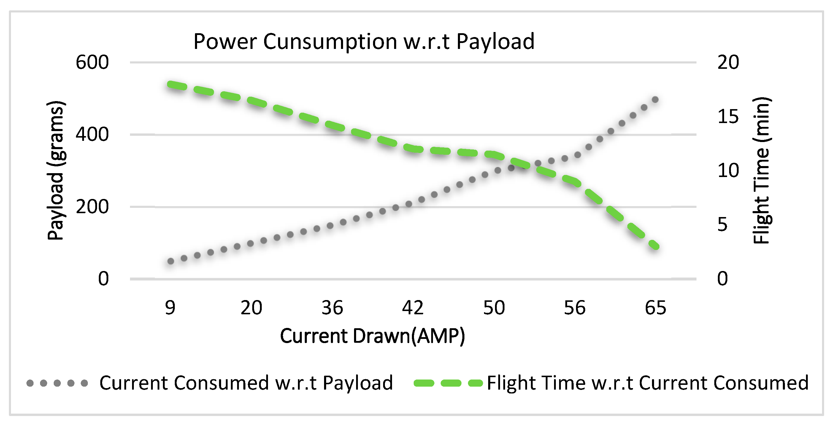
4.4. Power Consumption
With the increase in the weight of the payload carried by the quadcopter, the amount of required thrust also increased, which was directly proportional to the overall drawn current.
Figure 13 shows the trend of current consumption for the different masses of payload measured by the power module and received through the telemetry data. It also shows the variation of flight time against the drawn current.
As a result, the flight time provided by the battery also varied because it was inversely proportional to the current flow.
4.5. Response Time
A comparison was made between the quadcopter and a ground vehicle to observe the response time taken by both of them to reach the destination spot. For this purpose, an identical test field was provided to both the vehicles with similar start and finish points.
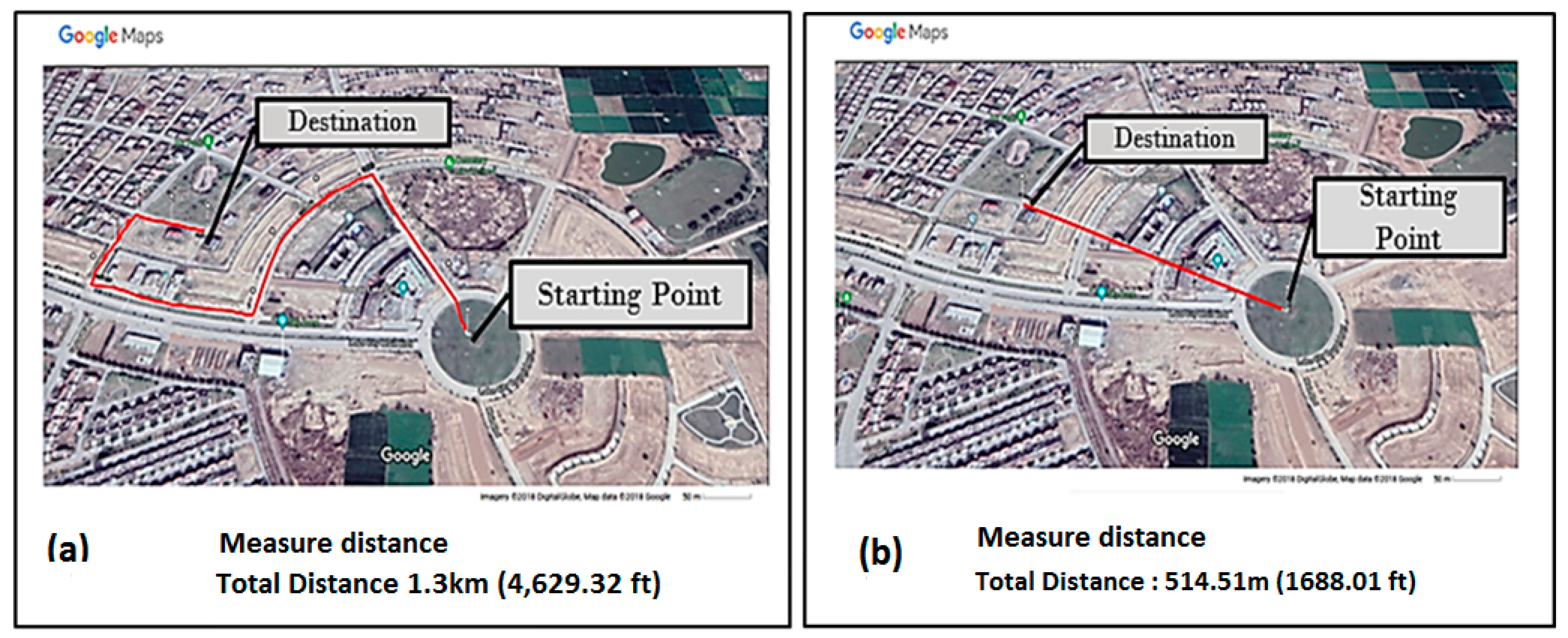
Figure 14a,b shows the path taken by the ground vehicle and the quadcopter, respectively.
With reference to
Figure 14, the ground vehicle had to cover a greater distance, i.e., 1.3 km, due to the lack of a straight path to the destination, while the quadcopter covered a short and straight aerial path, i.e., 514.5 m, to reach the same destination. Along with the problem of a long distance, another drawback of the ground vehicle was the speed variation that it had to face at the turning points in the path or due to traffic.
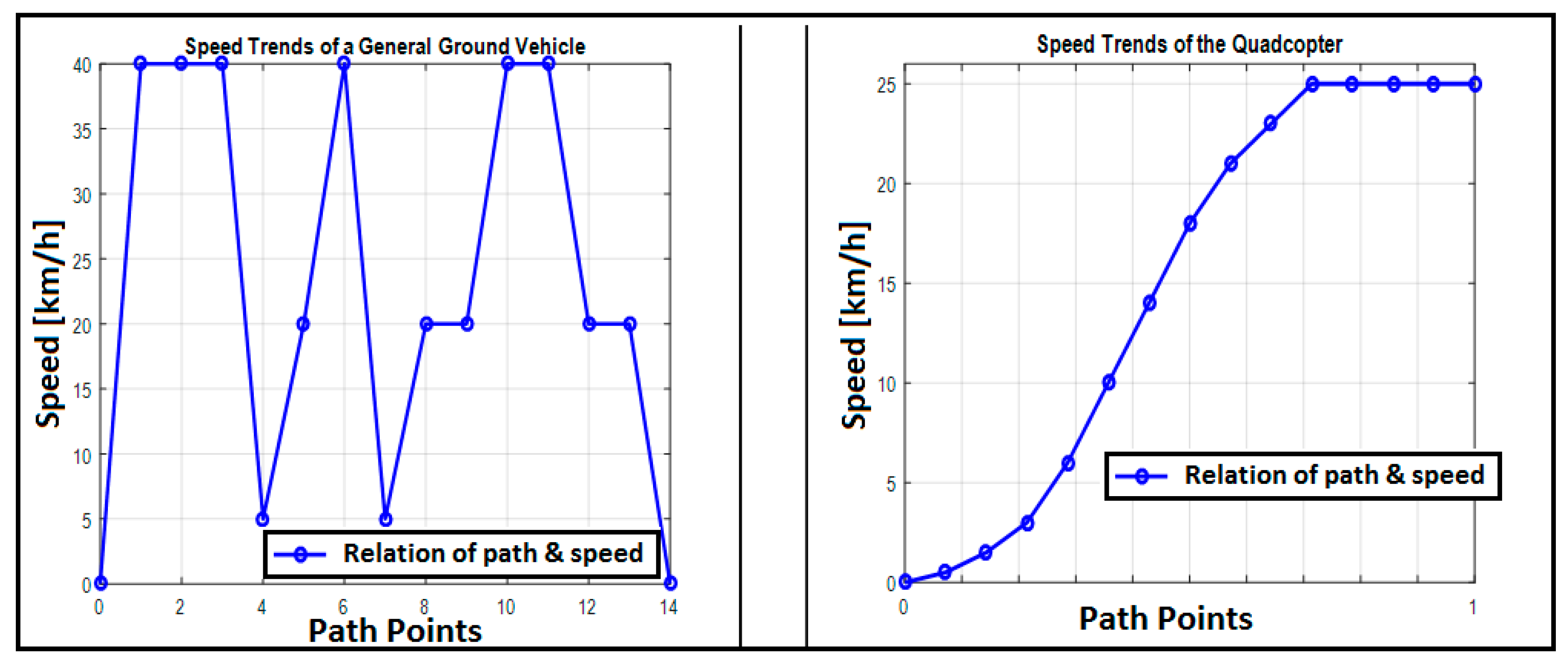
Figure 15 shows the speed variation of the ground vehicle and quadcopter, respectively. From the graph, the average speed calculated for the ground vehicle was 28 km/h (7.8 m/s), whereas for the quadcopter, it was 21 km/h (5.8 m/s). These average values were then used to approximate the response time for both vehicles in the comparison. The results were as follows:
Hence, this shows the improvement in the response time; therefore, employing a drone for first aid delivery would be extremely beneficial for both rescue and surveillance departments.
4.6. Flight Data Logging
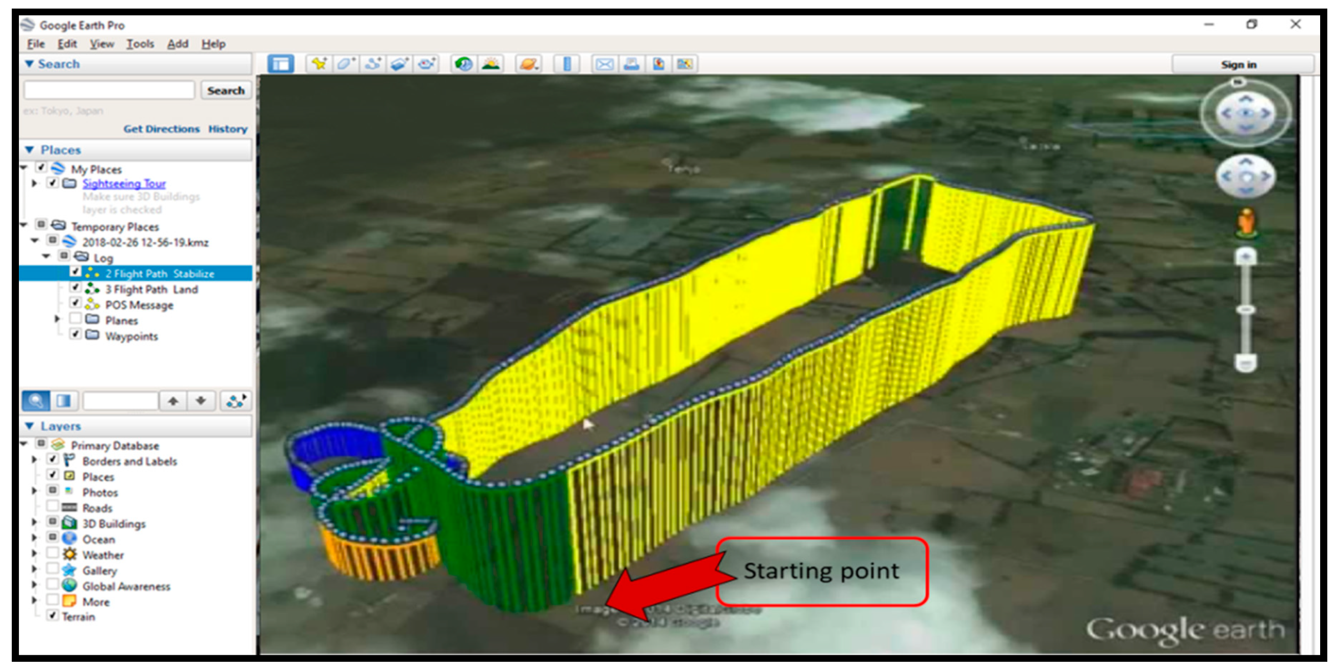
Real-time flight data were received from the telemetry link. The logs included the real-time GPS-based map of the complete flight with the actual elevation of the quadcopter. Furthermore, it also highlighted the flight mode interchanging during the flight. Google Earth software was used to view the logs.
Figure 16 shows the preview of the data log of a flight.
This data log-based map was used to debug the autonomous flight operation of the quadcopter. The color representation in this map is as follows:
It showed overall stability, which included altitude maintenance, as well as the feedback response against the air turbulence during the flight. As an example, it is visible in
Figure 16 that the quadcopter held at a constant altitude throughout the auto-navigation mode, then it decreased its altitude to hover until the time specified in the flight plan, and finally, it landed right on the spot from where it started the flight.
4.7. Experimental Debugging
Several test flights were carried out with a different configuration of flight parameters, and the results were observed as a percentage of the required performance.
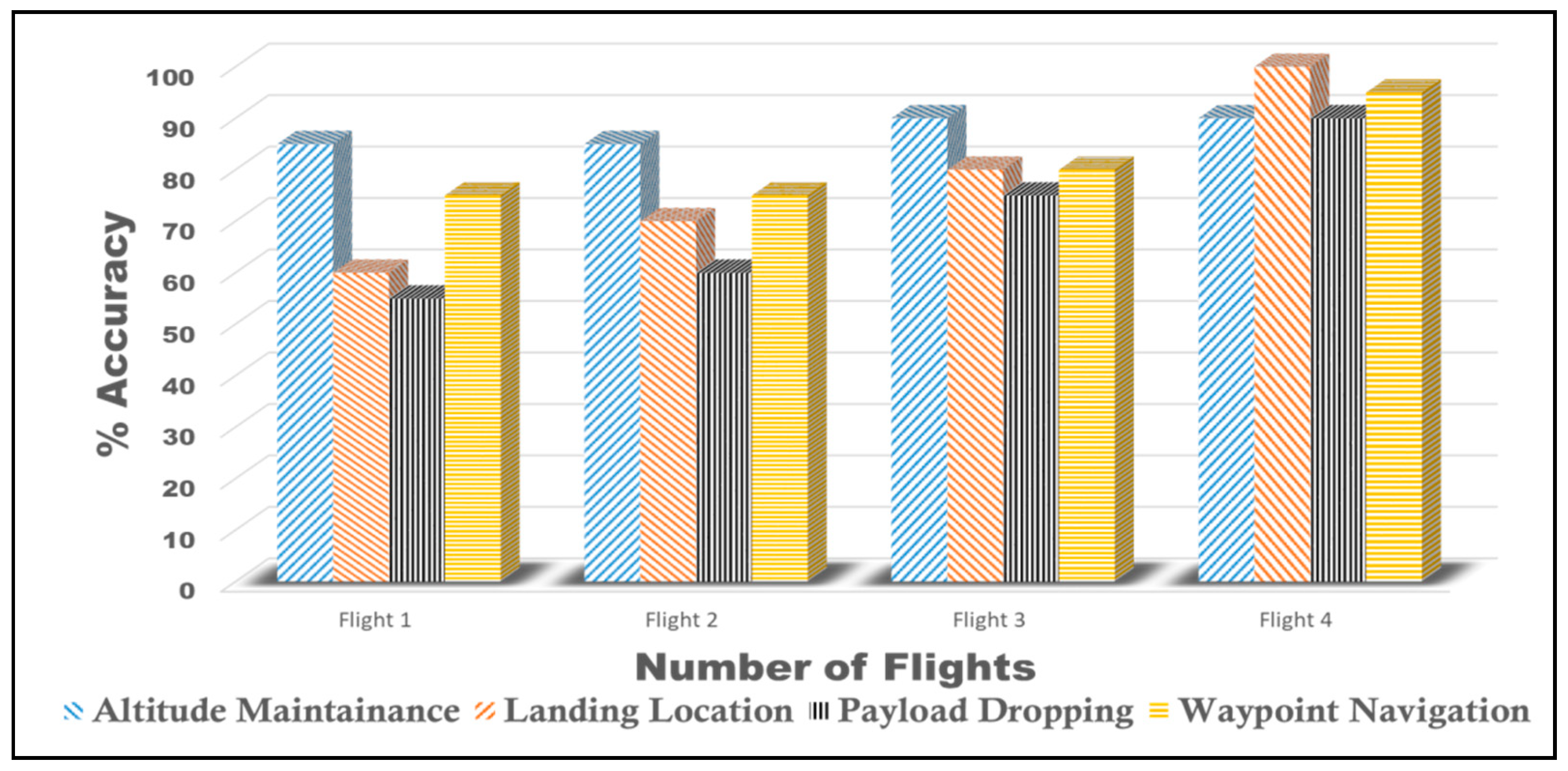
Figure 17 shows the performances of various flights, which improved to an acceptable level until Flight 4.
Results obtained from the data logs of each particular flight of
Figure 17 were analyzed as follows:
- ➢
Flight 1:
The selection of propellers and rotors was based on the exact required specifications, and the accelerometer’s calculated offsets were filtered through the Kalman filter’s gain matrix and error covariance matrix [
23,
24].
Q = process noise covariance
Pk = state error covariance matrix
Hk = measurement transition matrix
In Equation (7), the Kalman gain (Kk) was updated using the accelerometer’s offsets values. Thus, the altitude was maintained at the required level throughout Flight 1. However, the GPS of the quadcopter failed to communicate with the MCU due to an error in its baud rate configuration. Consequently, the location of payload dropping and the autonomous landing of the quadcopter on its return were not accurate because the MCU was not able to judge its location without communication with GPS.
- ➢
Flight 2:
Test Flight 2 was initiated after debugging the communication error by synchronizing the baud rate of the connection between the GPS module and the controller. Before takeoff, a considerable level of ping in the connection between the GPS and the controller was monitored. In accordance with the revised programmed autonomous flight commands, the quadcopter should land at the spot from which it took off. However, similar to Flight 1, a considerable error in the landing location remained in Flight 2 s as well. In other words, the attached first aid supply did not drop at the required position. This error was quantified in Flight 3.
- ➢
Flight 3:
Since the brushless motors drew a large amount of current, therefore a significant amount of magnetic induction was produced in the quadcopter’s chassis. This interference frequently broke the GPS connection with the satellite and caused error both in Flight 1 and Flight 2. By experimental observation, we used a dedicated placement mount for the GPS module to elevate it from the quadcopter’s main chassis. As a result, the GPS module kept a solid lock with the satellites, which enabled it to accurately drop the first aid supply at the specified longitude-latitude values. Moreover, the quadcopter landed precisely on the spot of takeoff.
- ➢
Flight 4:
In Flight 3, the problem of altitude maintenance and payload dropping at the desired location was resolved with 80% efficiency. Since the overall effectiveness of the autonomous flight depended significantly on the waypoint navigation throughout the path, therefore to improve it for the autonomous flight, the radius of each waypoint was reduced to 5 m. In other words, the quadcopter would continue to navigate a particular waypoint until it reached within a 5-m radius. The overall efficiency due to the waypoint navigation and quadcopter’s landing location achieved over 90%.


