Article

A Practical Deployment of a Communication Infrastructure to Support the Employment of Multiple Surveillance Drones Systems

1
Electrical Engineering Graduate Program, Federal University of Rio Grande do Sul (UFRGS), Porto Alegre 91501-970, Brazil
2
Institute of Informatics, Federal University of Rio Grande do Sul (UFRGS), Porto Alegre 91501-970, Brazil
3
School of Electronic and Information Engineering, Shanghai Dianji University (SDJU), Shanghai 200240, China
*
Author to whom correspondence should be addressed.
Drones 2018, 2(3), 26; https://doi.org/10.3390/drones2030026
Submission received: 21 July 2018 / Revised: 10 August 2018 / Accepted: 10 August 2018 / Published: 13 August 2018
(This article belongs to the Special Issue Advances in Drone Communications, State-of-the-Art and Architectures)

Abstract

:
In many incidents involving amateur drones (ADr), the big challenge is to quickly deploy a surveillance system that countermeasures the threat and keeps track of the intruders. Depending on the area under concern, launching a single surveillance drone (SDr) to hunt the intruder is not efficient, but employing multiple ones can cope with the problem. However, in order to make this approach feasible, an easy to use mission setup and control station for multiple SDr is required, which by its turn, requires a communication infrastructure able to handle the connection of multiple SDr among themselves and their ground control and payload visualization station. Concerning this Issue, this paper presents a proposal of a network infrastructure to support the operation of multiple SDr and its practical deployment. This infrastructure extends the existing Micro Air Vehicle Link (MAVLink) protocol to support multiple connections among the SDrs and between them and a ground control station. Encouraging results are obtained, showing the viability of this proposed protocol extension.

1. Introduction

The usage of drones is becoming increasingly popular, due to the great flexibility to implement many different applications and the important cost reduction of the available small amateur drones (ADr) platforms on the market [1]. However, this massive usage of ADr comes along with the danger of uncontrolled flights over areas in which important public safety issues must be considered. For instance, the flight of ADr near airports may put its operations in danger as a landing or a taking-off aircraft may collide with such a ADr resulting in a tragedy. Authorities are aware about this risk and once a threat like this appears, the airport must be suspended. However, suspending an airport operation may cause innumerous problems, related to delayed flights and missing connections, which may affect the whole international flights network! A concrete example of this situation occurred in September 2016, in which an ADr flying near the Dubai Airport forced to ground all flights for half an hour, causing incoming flights detours to other close by airports and delaying the takeoff of many outgoing ones [2]. In order to handle the situation, a manned helicopter with 3 people as crew were activated to try to locate and eliminate the intruder ADr, but without success. The airport started operating again after half an hour when the drone just disappeared.
The example of the Dubai Airport shutdown is emblematic, as just 30 min stop in the operations caused losses of thousands of dollars besides messing the flights’ network as it is a big airport with several flights coming and going for all over the world. The usage a manned helicopter to locate the drone proved to be unsuitable as it was reported by the crew, the ADr moved too fast and in sharp angles that the helicopter was not able to follow, then just few seconds after they managed to locate it, it just disappears. In this context, it is clear the need for a solution that can really address the problem, being able to be fast deployed and that can keep track of the ADr. A possible solution could be the usage of a SDr to search the ADr, which in a way could solve the problem related to the inability of a manned helicopter to follow the ADr. However, considering the large area of an airport, this approach is also questionable as the single SDr may be searching in one place and the ADr be in the opposite side of the airport and one the SDr manages to get there, the ADr can just have disappeared. So, the usage of a single SDr does not address completely the problem. Having several single SDr remotely operated would not be also efficient, as it would require one controller for each SDr, besides the human dependent coordination to organize their employment.
Observing the ADr intruder scenario as the one presented in the Dubai Airport, and the inability of the above discussed possible solutions to address the problem, different solutions have been proposed and are under investigation, among them it is possible to mention the usage of different types of jammers, grippers and multiple SDr, as fully described in recent works found in the literature, such as Refs. [3,4,5]. Particularly interesting for this work, multiple SDr could divide the work of hunting the ADr, controlled by a single ground control station, and that could be quickly deployed by a single operator [6]. This operator can setup the mission and control its unrolling by a single interface. From the mission goal perspective, this approach seems to be perfect, but in order to deploy it, a communication infrastructure allowing the communication among the SDr and between them and the ground control station is required. Regarding this issue of controlling multiple small drones, few proposals are found in the literature, such as Ref. [7], which besides of trying to address the problem, lacks from scalability as it relies on an approach using a relay node just to extend the communication range of the control base station. Proposals of using multiple drones, such as the one presented in Ref. [6] or those surveyed in Refs. [3,4], assume that this infrastructure, including communication and control facilities, already exists, however, it is still an open research area [5].
Anyway, communication technology for Unmanned Aerial Vehicles (UAVs) is an area in rapid development [8,9,10], in which it is possible observe a convergence of different technologies such as those in the internet of things domain [11,12]. Focusing particularly on small drones, it is possible to highlight a well-known and widely used upper layer communication protocol used to connect and control small drones, the Micro Air Vehicle Link (MAVLink) [13], which is employed in most of the ground control stations and small drones’ connections. However, this protocol in its current form, is not able to handle multiple connections among drones and between them and a single control station. Regarding this problem, this work reports the proposal of a communication infrastructure to support the coordinated operation of multiple drones and its control by a single ground control station. This proposal extends the MAVLink protocol besides of adapting an extensively used drone control ground station, the DroidPlanner [14], to support the simultaneous operation of multiple drones. Thus, it is possible to state that the major contributions of this work are to provide a feasible architectural solution for the multiple SDr model, such as those found in the literature, and a communication infrastructure able to support this architecture. It is important to note that this architecture, along with its infrastructure, can be used for different types of particular solutions, i.e., drones equipped with grippers, jammers or any other possible particular way to intercept the intruder ADr, as well as it could also be extended or adapted to other application, such as crowd monitoring or rescue applications. However, the scope of this paper is limited to the contributions mentioned above, leaving the other possibilities of its employment and particular implementation to be explored by others in future works.
After introducing a short overview of the DroidPlanner Control Station, reviewing the principals of the MAVLink protocol and discussing relevant related works, the architecture of the multiple SDr controller is presented and then the proposed communication infrastructure is detailed. A validation deployment along with the acquired results are then provided and finally, the conclusions are drawn providing directions for future work.

2. Background and Related Work

2.1. DroidPlanner and MAVLink in a Nutshell

DroidPlanner [14] is a ground control station for UAVs, which allows to control a single UAV at a time. Even its third version provided by the 3D Robotics company, which is called Tower and provides different enhancements in relation to the previous version, it still able to only control one UAV at once. It is released under the General Public License (GNU), which motivated other developers been engaged to the project.
The basic operation of the application is based on the exchange of messages among mobile devices (Android-based SmartPhones or Tablets) and UAVs using the MAVLink protocol. Messages sent from the DroidPlanner to the UAV represent actions used to control the vehicle platform. The messages sent from the UAVs describe their current state, consisting in telemetry and location information. In addition to the commands, the control station is able to create tasks, defining points of interest (POI) on the map to be visited by the UAV, as well as way-points describing the route towards the POIs.
The MAVLink protocol [13] is a communication protocol widely used by small UAVs/drones developed under the LGPL license. It is a lightweight protocol, which is ideal for exchanging small amounts of data between the control station platform and the UAV, avoiding high processing costs to handle these messages. The message structure consists of a set of mandatory fixed size fields (1 Byte each), i.e., the header, and an optional payload filed containing the message data to be transmitted. The message size varies from 8 to 263 Bytes.
Each MAVLink message is identified by a value in the identifier field in its packet header and has its built-in content in the payload data field. The messages are logically defined by an XML document, which can represent the types of data being transmitted and the order in which the application should interpret and process the received bytes. The protocol also allows the specification of new messages for communication between application specific purposes. To define a new message, it is necessary to represent it as a XML file, which is then automatically converted by a code generation tool.

2.2. Related Work

The research on networks of drones is gaining highlight as their usage is being considered to a very large number of applications. Depending on the application, the problems related to message handover may be an important issue to be considered. In Ref. [15], a handover mechanism for these aerial networks is proposed, which the authors claims that significantly differs from the conventional two-dimensional schemes. Their proposal adjusts the height and the distances between the drones, by using a seamless handover success probability to evaluate the optimal coverage decision algorithm. In Ref. [10], the authors propose a self-organizing mechanism to support the movements decisions of UAVs so that they maintain a connected network which can serve as relay to other nodes on the ground in the context of military operations. These two above mentioned works present interesting solutions to network connectivity and handover, which are indeed important issues to handle. However, they lack practical deployment as here presented. In Ref. [16], a multi mobile sensor system for target tracking is presented. The paper is heavily supported by mathematical proofs of the best distribution of the mobile sensors to accomplish the tracking mission. Despite handling the problem related to the coverage of the target, the authors take the communication infrastructure for granted, which in fact is not the case in reality. On the other hand, as here presented, an infrastructure to support the operation of multiple SDr is presented. The work presented [7] describes a proposal to control multiple UAVs through a ground station. In this proposal, the UAV communication network is organized in a mesh and the ground station communicates with the UAVs via the nearby UAV. This UAV is responsible for forwarding the messages to the others. Despite the possibility to communicate with all UAVs via the mesh network, the proposal in Ref. [7] does not allow the ground station to communicate with more than one UAV at the same time, the communication is always made between the ground station and nearest UAV, and then, multi-hop until reaching the destination. On the other hand, in the work here presented, the ground station can directly control each of the UAVs that are in the communication range, as well as it is possible relay messages through the UAV-network using multi-hop connections. In Ref. [17], a ground station simulator for UAVs using Hardware In The Loop (HITL) the technique is presented. This ground station is able to configure a wide range of parameters for UAV flight missions as well receive flight telemetry data. However, only point-to-point communication is supported between the ground station and each UAV. Thus, to control multiple UAVs, it is multiple instances of the control software must be opened. Compared to the work here presented, this platform does not scale with the number of UAVs. The same comparison is valid for the solution proposed [18] in which, despite the possibility of loading tasks for multiple UAVs, the communication with each of them also occurs in a point-to-point fashion.
Another important problem to be handled in surveillance systems based on battery-driven UAVs is the concern about energy consumption. In Ref. [19] this concern is handled by proposing an improved Mixed Integer Linear Programming (MILP) model that serves to support the orchestration of system to refuel the UAVs allowing persistent mission execution. In line with this concept of persistent mission execution, Ref. [20] presents a network architecture and a supporting optimization framework that allows UAVs to perform city-scale video monitoring. The authors address the energy consumption concern by defining a mathematical framework for selecting the UAVs for periodic re-charging by landing on public transportation buses during their monitoring missions. They work was validated by simulations, but it could benefit from the communication architecture and mission control station for multiple drones that is proposed in this current paper for its practical deployment.

3. Materials and Methods

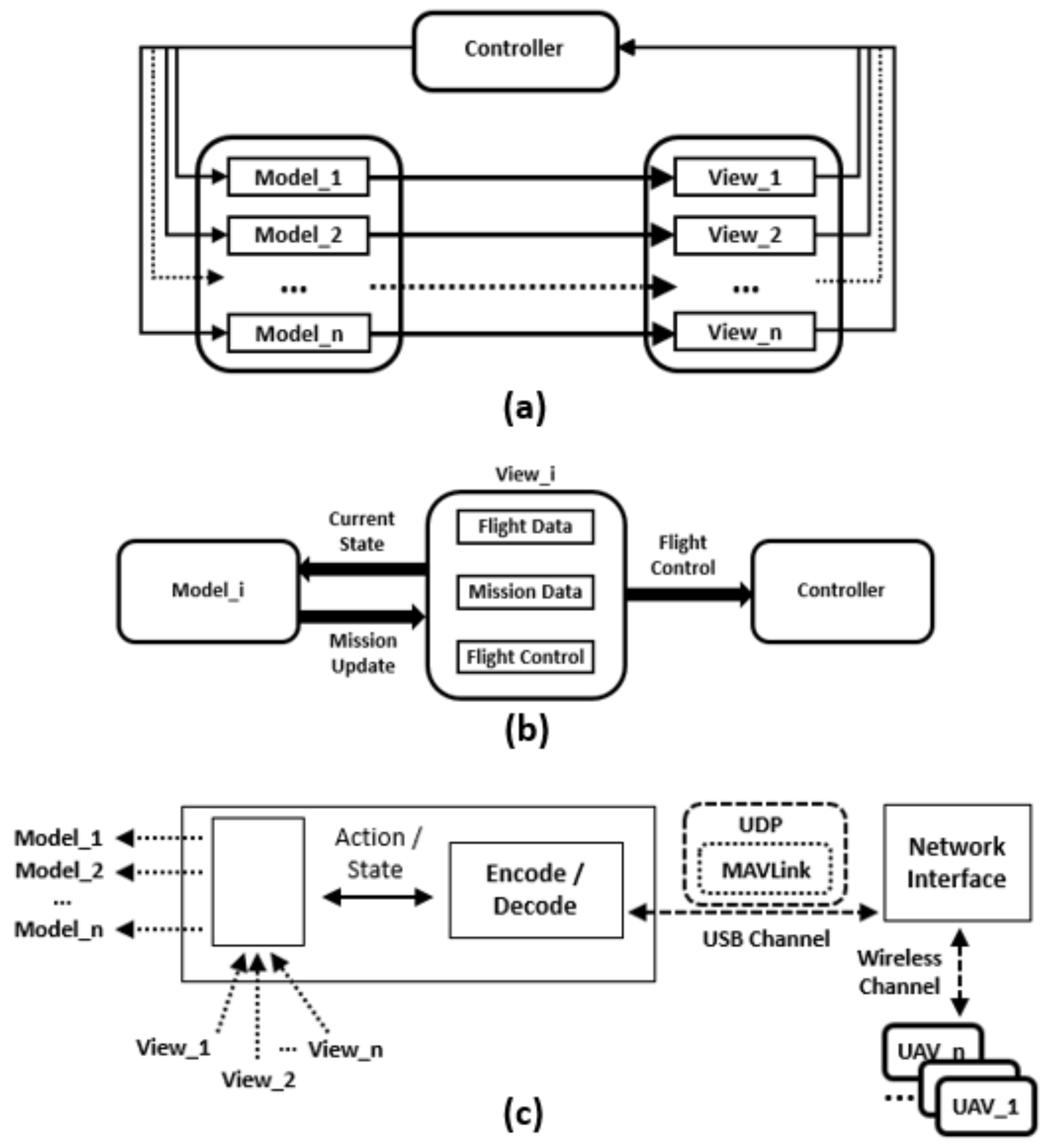
3.1. Multiple Drones Control Station Architecture

The proposed multiple Drones Control Station extension based on the DroidPlanner platform employs an architecture based on the Model-View-Controller (MVC) pattern, the used in the original control station, allowing the independent implementation of different modules that are integrated at the end. However, some changes in the original MVC architecture had to be made to enable the introduction of new communication support features. Figure 1a presents a diagram representing the adopted architecture and the communication among the three components of the used MVC model. The controller tier is responsible both for receiving data as sending data from the platform to the UAV. The view corresponds to multiple instances of the original interface, and finally, the model represents the virtualization of multiple UAVs controlled by the system.
The model component is responsible by virtualizing physical drone in the system, saving and changing their status based on the received MAVLink messages. In addition to storing information about UAVs, this component notifies the interface about the changes in their status. In other to represent multiple drones, this component of the MVC architecture is replicated according to the number of the drones to be controlled. Each instance of the model component contains data about the drone it refers to, corresponding to flight, mission control and navigation data. All messages received by the control station and destined for the corresponding drone are processed by the respective model, changing the necessary component instance to finally notify the interface about changes.
The view component represents the user interface. It shows all changes in the model and receive all user actions to control the multiple drones. This component was also replicated in as many instances as the number of drones being controlled. Each instance in the view tier is responsible for updating information about the drone being controlled and for receiving user actions to control that drone. Figure 1b illustrates the internal composition of each view component instance as well as its interaction with the other architectural elements.
The control tier is responsible to manage all incoming MAVLink messages, to decode these messages and to forward them and the correspondent control related to these messages to the internal correct representation of UAV (model instance). Additionally, this component also prepares messages to be sent to the physical UAV through the established communication link. The control unit also interfaces with the communication channel to contact the physical UAVs. The implemented communication infrastructure uses the User Datagram Protocol (UDP) protocol and it uses Universal Serial Bus (USB) serial channel to access the network interface device. Figure 1c illustrates all these connections in the depicted diagram. The control tier classifies the incoming messages to correctly deliver them to the virtualized model corresponding to the issuer UAV. The message send action aggregates all the messages and sends them sequentially as they are delivered to the communication interface.

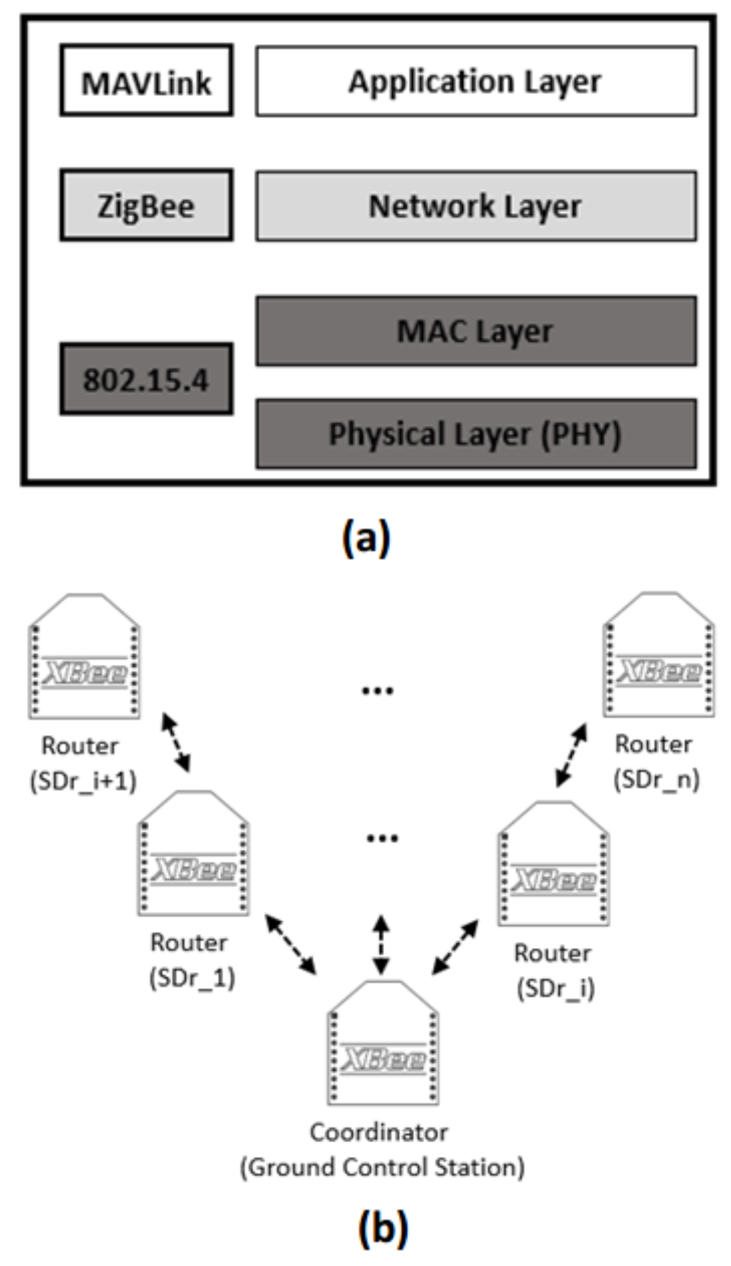
3.2. Communication Infrastructure

The communication infrastructure relies on the upper-level MAVLink protocol and on base network protocols for the network, medium access and physical layers. The basic requirements to deploy the intended network to support the operation of multiple SDr are that it must be possible to send and receive data related to the mission semantics, i.e., definition of the area to be covered, support multiple nodes identification, then it must support unicast, broadcast and multicast, besides being physically light-weight to be carried by small drones as well as light-weight in terms of communication overhead. Observing these basic requirements, an extension to MAVLink is proposed and the use of a ZigBee underlaying network was selected, as detailed in the following.

3.2.1. Definition of the New MAVLink Message

As introduced in the beginning of this paper, the goal of the proposed communication infrastructure is to support the operation of multiple SDr controlled by a single ground control station. The architecture of this station, already presented in the previous section, highlighted the need for multiple nodes identification, so that each drone can be mapped to its correspondent internal model in the ground station. Additionally, as the idea is to use several drones to survey a given area to hunt an ADr, the communication protocol has to support the definition of items related to the mission semantics, such as the waypoints to follow or coordinates that describes a given area of interest to be covered and patterns of interest to be recognized, such as the description patterns to be used by an internal pattern recognition software. Besides these semantic information, it is also necessary to identify the specific internal component in the drone that will handle a given request or will send information to the control station, for example, it can be a hardware component, such as a given sensor that provides telemetric information (wind speed, humidity, temperature, among other) or a software component, such as an onboard image processing algorithm that is able to identify an ADr and inform the base station.
In order to address these needs, a new MAVLink message containing customized information was defined. According to the MAVLink development chain, the message was defined in Extensible Markup Language (XML) format which was then translated to Java code. The message contains three fields: The first is named target_system and allows the uniquely identification of a node in the network, being possible to address up to 255 nodes in the network. The second is named target_component, which allows addressing a specific internal component in the drone (up to 255) or making possible the base station correctly interpret an incoming message from a drone in the control module. Finally, the third field named recognition_pattern allows the exchange of information mission semantics information, such as waypoints and patterns to be used by onboard image processing algorithm, or movement patterns to be followed, such as zigzag movement or circles, for instance. The patterns (both for movement or image recognition) are configured beforehand being possible to define up to 255 patterns, according to the size of the payload in the MAVLink message allocated to the pattern code.
As MAVLink does not provide inherent security mechanisms, in order to provide security to MAVLink messages exchanged in the proposed communication infrastructure, it highly recommended that once this proposed communication infrastructure be used in a real application, these MAVLink messages be encapsulated in other protocols able to offer higher security standards, such as Datagram Transport Layer Security (DTLS).

3.2.2. The Practical Network Implementation

In order to address the above described requirements for the lower-level communication infrastructure and the physical light-weight mandatory requirement, a XBee—ZigBee Series 2, extended range provided by Digi ® was selected. This module uses IEEE 802.15.4 Physical and Medium Access Control (MAC) standard and as ZigBee enable, it supports point-to-point and point-to-multiple topologies, besides Peer-To-Peer and mesh networks. This module also provides smart energy management features, which allows lower energy consumption. Combined to upper-level MAVLink protocol, the protocol stack of the proposed infrastructure is depicted in Figure 2a.
The ZigBee network consists of three different node types: coordinator, router and end-devices. The coordinator node is a sort of network leader, which is responsible to establish the network. There is just one coordinator in the network. The router is a node that is capable to relay data to other nodes. This type of node has also Delay-Tolerant capabilities [21], as it is capable to store data that should be delivered to nodes that are not immediately reachable. End-devices are generally low-power devices, such as sensor nodes, that communicate with a router or the coordinator but do not forward data. In the proposed network setup, this type of node is not used.
The deployed network is then composed of just a coordinator node, i.e., the ground control station, and the multiple SDr having their XBee module configured as routers. Using them as routers makes possible to extend the range of the network by multi-hop connections. The addressing scheme used the two ZigBee networks addresses, a 64-bit manufacture built-in address and a configurable 16-bit network address. The network uses the configurable 16-bit network address in the communication, but in case of address conflict, the 64-bit built-in address is used to solve the conflict to guarantee the data transmission delivery. Figure 2b sketches the designed network topology.

4. Experimental Deployment

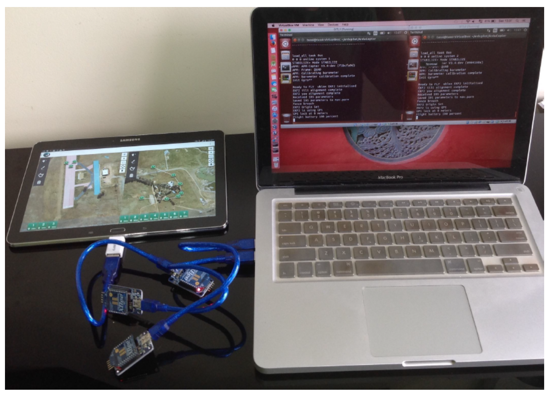
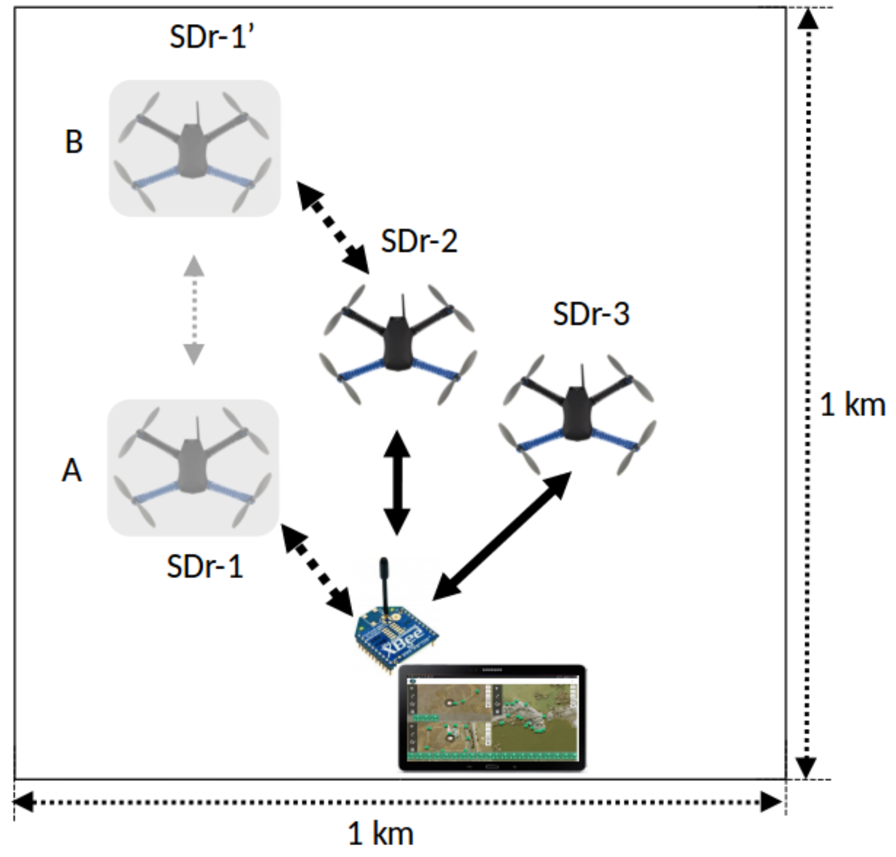
4.1. Experiments Setup

The first experiments were based on simulations using Software in the Loop (STIL) ArduPilot simulator [22]. The goal in using this approach was to validate the proposal by means of a realistic environment which includes parts of the real system (the communication modules) and realistic models of drones, by using ArduPilot, which enables keeping the realism in relation to the physical properties of the simulated drones.
For each drone to be controlled in the performed simulations, it was necessary to run a new instance of the simulator, assigning to each simulated drone a unique identifier, a key parameter that allows the ground control station to recognize messages received from each instance of the simulator. Networks with up to four drones were tested. Regarding the simulation process, it basically consists of exchanging MAVLink messages between the control station and the simulated drones, assigning them missions and receiving their telemetric data. Analyzing incoming messages, it is possible to get the application state, thus validating the implementations made in DroidPlanner control station, the extended MAVLink protocol and the complete designed network infrastructure. For the ground control station it was used a Samsung Galaxy Note 10.1 2014 Edition, with Quad core 1.9 GHz + Quad core 1.3 GHz and 3 GB LPDDR3 Random Access Memory (RAM), running Android 4.3 (Jelly Bean) operating system.
Figure 3 presents the setup of the performed experiments using simulations, in which a notebook was used to run the simulated drones in the STIL simulator.
After the performing the proposal validation with the above described simulations, tests on the field were performed using 3 drones 3D Robotics Iris+ quadcopter. The tests resumed in sending and receiving messages, in the same way performed in the simulations, in which the XBee modules were connected via a USB port to Raspberry PI3 computing platforms integrated to the PixHawk computer in the quadcopters. The drones were flying in a region of 1 km × 1 km, as presented in the schematic depicted in Figure 4. In this figure it is possible to observe that SDr-1 moves back and forth between positions A and B, while the two others are keeping their positions. These dynamics allowed to test the situation with two and three simultaneous connections of the SDrs to the base station, as well as the multi-hop communication to the SDr-1 in position B via SDr-2.
Both simulation (STIL tests) and test on the field took 900 s each, period in which the drones sent messages control station and the control station commands to the drones. The commands that were sent represented arbitrary addition and removal of waypoints. The drones sent telemetric messages to the base station with their position and platform status (including battery level) each half second. In the simulation tests, 100% of the packets sent were received while in the tests performed on the field this percentage dropped to 97%.

4.2. Results and Discussion

Experiments were performed with two, three, and four drones being controlled at the same time (with four only with the STIL simulation). Figure 5 presents screenshots of the ground control station controlling one up to four drones. In Figure 5a, in which just one drone being controlled, the highlight is given to the menu in the right-hand side, which allows the user select the type of recognition movement pattern he/she wants that the drone perform. In this example, it was previously configured two different types: Zigzag movement and the default waypoint following movement. For the airport security application highlighted in introductory section, suitable patterns could be defined and uploaded. The selected command is encapsulated in the recognition_pattern field of the defined MAVLink message described above and sent through the communication infrastructure.
In Figure 5b, with two drones being controlled, highlight is given to the option select waypoint, in which it is shown the user selecting the waypoints to be followed by each of the two drones in the pop-up menus. On the bottom of each window, it is possible to observe the sequence of waypoints for each of them. According to the mission unfold, when the drones reach each of these waypoints, MAVLink messages are sent to control station updating the drone status.
In Figure 5c, with three drones being controlled, the highlight is given to the routes shown in each window, as well as to the sequence of waypoints on the bottom. Notice that on the left, there is a menu bar that allows the user to draw a path to be followed by the drone.
In Figure 5d, four drones are controlled and the highlight is given to the telemetric information of all of them. This information is displayed on the left side and upper bars, along with the control menus on the bottom of each window. In this control menu, one interesting command is the follow command, which makes the drones follow a given object that was recognized by its onboard pattern recognition algorithm.
For a greater number of vehicles, there is a limiting factor related to the overload of elements in the Graphic User Interface. For better usage, a larger display would be beneficial. Concerning the proposed communication infrastructure, the system worked as intended to with up to four drones being controlled. Messages were successfully delivered and no major delays were detected. For the defined mission semantics up to now, the defined MAVLink message is supportive and there are still more than 50% of available space to extend the messages semantics. Besides of being implemented using IEEE 802.15.4 and ZigBee, the proposed approach is modular and allows interchangeable usage of other technologies, with minor adaptations.
In the tests performed on the field it was possible to observe that 3% of packets sent were lost, which can be explained by the link instability, particularly when the SDr-1 was moving between positions A and B (see Figure 4). Despite the occurrence of these packets drops, no data was missing as retransmissions were done. It is important to highlight that the overhead represented by these retransmissions is not high for this particular scenario. Other experiments are planned to be performed in harsher environments in which interference in the data communication may happen, but this discussion is beyond the scope of this current paper.

5. Conclusions

This work highlights the possible usage of multiple drones controlled by a single control station to perform surveillance missions, which can focus different types of targets, including ADr. A real application scenario was highlighted in the introductory section, stressing the need for such type of multiple drones’ systems. However, it was also stressed the need for communication solutions to address the control of multiple drones, and this was the goal of this work, present a practical implementation of a suitable communication infrastructure to support multiple drones’ systems, which included the extension of the MAVLink protocol to support addressing multiple drones in a network. Additionally, a multiple drones’ control station was developed and its architecture was detailed described. Experiments were performed and showed the suitability of the proposed approach, highlighting both communication and user interface aspects.
Future works are expected address the usage of different technologies in the bottom network layers, allowing even more extended ranges then the one provided by the current used modules. Moreover, fault tolerance mechanisms have to be included to avoid jamming attacks, as well as security measures to avoid eavesdropping or message spoofing or connection hijacking, before putting the system working in real-world large scale.

Author Contributions

E.P.d.F. and H.W. supervised the whole study, validated the results and reviewed the paper. C.E.T.L. developed the mobile application and the implemented the communication using XBee modules and performed the simulations. I.Z. and M.B. wrote the paper and performed the tests on the field.

Funding

The authors thank to State of Rio Grande do Sul Research Foundation (FAPERGS), Brazilian National Council for Scientific and Technological Development (CNPq), and Shanghai Dianji University for the partial financial support to perform this work.

Acknowledgments

The authors thanks to the Brazilian Research Funding Agencies CNPq, CAPES and FAPERGS for the partial financial funding provided for this research.

Conflicts of Interest

The authors declare no conflict of interest.

Abbreviations

The following abbreviations are used in this manuscript:
UAVUnmanned Aerial Vehicle
ADramateur drone
SDrsurveillance drone
GNUGeneral Public License
POIPoint Of Interest
MVCModel-View-Controller
UDPUser Datagram Protocol
USBUniversal Serial Bus
MAVLinkMicro Air Vehicle Link
RAMRandom Access Memory
MACMedium Access Control
XMLExtensible Markup Language
STILSoftware in the Loop
DTLSDatagram Transport Layer Security
MILPMixed Integer Linear Programming

References

  1. Ping, J.T.K.; Ling, A.E.; Quan, T.J.; Dat, C.Y. Generic unmanned aerial vehicle (UAV) for civilian application-A feasibility assessment and market survey on civilian application for aerial imaging. In Proceedings of the 2012 IEEE Conference on Sustainable Utilization and Development in Engineering and Technology (STUDENT), Semenyih, Malaysia, 20–21 October 2011; pp. 289–294. [Google Scholar]
  2. BBC. Dubai Airport Grounds Flights Due to ‘Drone Activity’. 2016. Available online: http://www.bbc.com/news/world-middle-east-37493404 (accessed on 12 May 2017).
  3. Kaleem, Z.; Rehmani, M.H.; Ahmed, E.; Jamalipour, A.; Rodrigues, J.J.P.C.; Moustafa, H.; Guibene, W. Amateur Drone Surveillance: Applications, Architectures, Enabling Technologies, and Public Safety Issues: Part 1. IEEE Commun. Mag. 2018, 56, 14–15. [Google Scholar] [CrossRef]
  4. Kaleem, Z.; Rehmani, M.H.; Ahmed, E.; Jamalipour, A.; Rodrigues, J.J.P.C.; Moustafa, H.; Guibene, W. Amateur Drone Surveillance: Applications, Architectures, Enabling Technologies, and Public Safety Issues: Part 2. IEEE Commun. Mag. 2018, 56, 66–67. [Google Scholar] [CrossRef]
  5. Azari, M.M.; Sallouha, H.; Chiumento, A.; Rajendran, S.; Vinogradov, E.; Pollin, S. Key Technologies and System Trade-offs for Detection and Localization of Amateur Drones. IEEE Commun. Mag. 2018, 56, 51–57. [Google Scholar] [CrossRef] [Green Version]
  6. Kaleem, Z.; Rehmani, M.H. Amateur Drone Monitoring: State-of-the-Art Architectures, Key Enabling Technologies, and Future Research Directions. IEEE Wirel. Commun. 2018, 25, 150–159. [Google Scholar] [CrossRef] [Green Version]
  7. Luo, C.; Ward, P.; Cameron, S.; Parr, G.; McClean, S. Communication provision for a team of remotely searching UAVs: A mobile relay approach. In Proceedings of the 2012 IEEE Globecom Workshops, Anaheim, CA, USA, 3–7 December 2012; pp. 1544–1549. [Google Scholar]
  8. Zeng, Y.; Zhang, R.; Lim, T.J. Wireless communications with unmanned aerial vehicles: Opportunities and challenges. IEEE Commun. Mag. 2016, 54, 36–42. [Google Scholar] [CrossRef]
  9. Xiao, Z.; Xia, P.; Xia, X. Enabling UAV cellular with millimeter-wave communication: Potentials and approaches. IEEE Commun. Mag. 2016, 54, 66–73. [Google Scholar] [CrossRef]
  10. Orfanus, D.; de Freitas, E.P.; Eliassen, F. Self-Organization as a Supporting Paradigm for Military UAV Relay Networks. IEEE Commun. Lett. 2016, 20, 804–807. [Google Scholar] [CrossRef]
  11. Motlagh, N.H.; Bagaa, M.; Taleb, T. UAV-Based IoT Platform: A Crowd Surveillance Use Case. IEEE Commun. Mag. 2017, 55, 128–134. [Google Scholar] [CrossRef]
  12. Zacarias, I.; Gaspary, L.P.; Kohl, A.; Fernandes, R.Q.A.; Stocchero, J.M.; de Freitas, E.P. Combining Software-Defined and Delay-Tolerant Approaches in Last-Mile Tactical Edge Networking. IEEE Commun. Mag. 2017, 55, 22–29. [Google Scholar] [CrossRef]
  13. Meier, L. MAVLink: Micro Air Vehicle Communication Protocol. 2009. Available online: http://qgroundcontrol.org/mavlink/start (accessed on 12 May 2017).
  14. Benemann, A. DroidPlanner 2. 2014. Available online: https://play.google.com/store/apps/details?id=org.droidplannerhl=pt (accessed on 12 May 2017).
  15. Park, K.N.; Kang, J.H.; Cho, B.M.; Park, K.J.; Kim, H. Handover Management of Net-Drones for Future Internet Platforms. Int. J. Distrib. Sens. Netw. 2016, 12, 5760245. [Google Scholar] [CrossRef]
  16. Kim, B.S.; Kim, S.W.; Zhang, C.; Yue, H. A breakthrough in multi-hop wireless multimedia sensor networking protocols. Int. J. Distrib. Sens. Netw. 2017, 13. [Google Scholar] [CrossRef] [Green Version]
  17. Ajami, A.; Balmat, J.F.; Gauthier, J.P.; Maillot, T. Path planning and Ground Control Station simulator for UAV. In Proceedings of the 2013 IEEE Aerospace Conference, Big Sky, MT, USA, 2–9 March 2013; pp. 1–13. [Google Scholar]
  18. Koh, L.; Wich, S.; Wuderlin, S.; Duffy, B.; Kerby, J.; Pang, K. Missionplanner. 2010. Available online: http://conservationdrones.org/mission-planner (accessed on 20 August 2018).
  19. Song, B.D.; Kim, J.; Kim, J.; Park, H.; Morrison, J.R.; Shim, D.H. Persistent UAV Service: An Improved Scheduling Formulation and Prototypes of System Components. J. Intell. Robot. Syst. 2014, 74, 221–232. [Google Scholar] [CrossRef]
  20. Trotta, A.; D’Andreagiovanni, F.; di Felice, M.; Natalizio, E.; Chowdhury, K. When UAVs Ride A Bus: Towards Energy-efficient City-scale Video Surveillance. In Proceedings of the IEEE INFOCOM 2018—IEEE Conference on Computer Communications, Honolulu, HI, USA, 15–19 April 2018. [Google Scholar]
  21. Araniti, G.; Bezirgiannidis, N.; Birrane, E.; Bisio, I.; Burleigh, S.; Caini, C.; Feldmann, M.; Marchese, M.; Segui, J.; Suzuki, K. Contact graph routing in DTN space networks: Overview, enhancements and performance. IEEE Commun. Mag. 2015, 53, 38–46. [Google Scholar] [CrossRef]
  22. ArduPilot Dev Team. Software in the Loop (STIL) ArduPilot Simulator. 2016. Available online: http://ardupilot.org/dev/docs/sitl-simulator-software-in-the-loop.html (accessed on 13 May 2017).
Figure 1. Ground Control Station Architecture: (a) Overall MVC design. (b) Detailed interaction of the architectural components. (c) Control and network interfaces.
Drones 02 00026 g001
Figure 2. Practical Network Implementation: (a) Protocol Stack. (b) Network Topology.
Drones 02 00026 g002
Figure 3. Experimental Setup: Ground Control Station running on the Android Tablet; two instances of drones running in the STIL in the notebook; and the XBee modules used as communication devices.
Drones 02 00026 g003
Figure 4. Schematic representation of the performed tests.
Drones 02 00026 g004
Figure 5. Screenshots of the ground control station: (a) controlling just one drone—highlight in the righthand side the recognition options menu; (b) controlling two drones—highlight in the waypoint selection menus; (c) controlling three drones—highlight in the waypoint sequences on the bottom of each windows; (d) controlling four drones—highlight in the telemetric information on the left hand side of each window and on the bottom the controlling menus.
Drones 02 00026 g005

