Article

GeoSOT-H-Enabled Risk-Aware Hierarchical Path Planning and Emergency Replanning for Urban Low-Altitude UAV Missions


1
College of Air Traffic Management, Civil Aviation Flight University of China, Guanghan 618307, China
2
China Airport Construction Group Co., Ltd., Beijing 101300, China
*
Author to whom correspondence should be addressed.
Drones 2026, 10(8), 603; https://doi.org/10.3390/drones10080603
Submission received: 26 June 2026 / Revised: 1 August 2026 / Accepted: 3 August 2026 / Published: 5 August 2026
(This article belongs to the Special Issue Path Planning, Trajectory Tracking and Guidance for UAVs: 4th Edition)

Highlights

What are the main findings?
  • A GeoSOT-H-enabled 3D semantic-risk voxel model is developed to support risk-aware path planning for urban low-altitude UAV missions, integrating building hard no-fly zones, rooftop safety buffers, roads, water areas, and ordinary open airspace into a unified indexed airspace representation.
  • The proposed HSPC-A* framework combines L21 macro-corridor generation with L24-H corridor-constrained fine-level search, enabling UAV path planning to jointly consider path length, semantic-risk exposure, vertical maneuvering cost, and temporary no-fly constraints.
What are the implications of the main findings?
  • The proposed framework provides a structured basis for generating feasible voxel-based UAV paths in complex urban environments, supporting subsequent navigation or path generation processes for logistics delivery, inspection, and emergency-response missions.
  • The GeoSOT-H code-based update mechanism enables rapid insertion of dynamic no-fly zones and emergency replanning without reconstructing the full 3D risk field, improving the adaptability of UAV missions under changing low-altitude airspace constraints.

Abstract

Urban low-altitude UAV missions require efficient, risk-aware path planning and rapid response to dynamic airspace changes. This study proposes a hierarchical planning and dynamic replanning framework based on the Geographic coordinate Subdivision grid with One-dimensional integer coding on a 2n-Tree (GeoSOT) and height-layer encoding (GeoSOT-H). The framework constructs a multi-granularity 3D semantic-risk voxel model and uses semantic-triggered refinement to limit fine-resolution modeling to flight-relevant high-risk regions. The Hierarchical Semantic-risk-aware Path Planning with Corridor-constrained A* (HSPC-A*) algorithm generates a macro-corridor and conducts fine-level search to balance path length, semantic-risk exposure, and vertical maneuvering cost while satisfying no-fly constraints. Its output is a connected L24-H voxel-center path for subsequent navigation or post-processing. Experiments in a 2.89 km2 urban area show that explicit storage is reduced to 16.4% of full-domain L24-H voxels. Compared with conventional 3D A*, HSPC-A* slightly increases path length from 2183.06 m to 2202.38 m, while reducing average semantic risk from 8.5927 to 5.2595, eliminating high-risk samples, and reducing search time from 164.09 s to 3.74 s. Code-based updating achieved a 104.6-fold speedup, and two-branch replanning handled both corridor-retained and corridor-disconnecting no-fly events, jointly demonstrating the trade-offs among path length, semantic-risk exposure, computational efficiency, and compliance with modeled flight-safety constraints.

1. Introduction

Unmanned aerial vehicles (UAVs) have been widely applied in urban logistics, emergency response, infrastructure inspection, environmental monitoring, and other low-altitude scenarios [1,2,3]. Path planning is a core component of autonomous UAV operations, aiming to generate safe and efficient routes under flight, environmental, and mission constraints [4,5,6]. In dense urban low-altitude environments, however, planning is not merely a geometric shortest-path problem. Buildings, roads, water areas, rooftop facilities, altitude restrictions, and temporary no-fly events jointly affect route feasibility and operational risk [5,6,7]. UAVs must therefore avoid hard obstacles while limiting semantic-risk exposure and unnecessary vertical maneuvers. Recent UAV-image-based traversability assessment in hostile environments further indicates that irregular or unfavorable terrain conditions can affect mission feasibility and environmental perception, reinforcing the need to represent heterogeneous spatial constraints explicitly [8].
At the operational level, UAS traffic management and urban air mobility studies emphasize the importance of structured airspace organization, scalable route management, and coordination between individual trajectories and airspace-wide constraints [9,10,11]. Future UAV missions may also couple geometric planning with communication-related requirements. Dong et al. jointly optimized UAV-swarm trajectories and collaborative beamforming against mobile eavesdroppers using MAPPO [12], while Han et al. developed a deep reinforcement learning- and Stackelberg game-based spatial anti-jamming scheme for satellite networks [13]. These studies are not direct baselines for the geometric path-planning problem considered here, but they broaden the application motivation by showing that future low-altitude operations may need to accommodate airspace risk, communication security, interference resilience, and dynamic environmental constraints within a coordinated mission framework.
In terms of airspace modeling, existing approaches mainly use vector data, local raster or voxel grids, and discrete global grid systems (DGGSs). Vector models accurately describe geographic-object boundaries but are not directly suited to voxel-level neighborhood expansion and graph search. Local raster grids are readily integrated with conventional planners, but they generally depend on task-specific coordinate systems and provide limited cross-region and cross-scale consistency. DGGSs provide hierarchical subdivision, globally consistent indexing, and multi-resolution spatial organization, offering a suitable foundation for integrating heterogeneous airspace data [14,15,16,17]. Nevertheless, different spatial indexes are designed for different purposes. H3 is effective for horizontal hexagonal aggregation and neighborhood analysis [18], S2 provides hierarchical indexing of spherical surface cells [19], and Geohash offers compact prefix-based longitude–latitude indexing [20]. These standard implementations primarily organize horizontal geographic space. The present study additionally requires altitude-layer coupling, explicit parent–child relationships between planning levels, cross-scale semantic-risk aggregation, and local updates of affected three-dimensional cells.
GeoSOT-H is therefore selected according to the requirements of this study rather than because it is universally superior to other spatial indexes. The GeoSOT framework provides hierarchical subdivision and one-dimensional spatial coding [21], and recent GeoSOT-based research has demonstrated its capability for organizing multi-source and spatiotemporal geographic data [22]. More directly related to UAV planning, Sun et al. combined three-dimensional earth-space subdivision with a grid-based DRL planning model [23]. ElSayed and Mohamed developed a dynamically updated digital-twin framework with four-dimensional airspace discretization and trajectory optimization [24], while Zhang et al. integrated GeoSOT indexing with JPS3D to accelerate large-scale three-dimensional path search [25]. These studies demonstrate the value of coupling spatial coding with path planning, but integrated support for planning-oriented semantic states, cross-scale risk consistency, constrained vertical movement, and local updating after temporary no-fly events remains limited. GeoSOT-H is adopted here to organize horizontal codes and altitude layers within a unified representation, providing the spatial basis for the proposed horizontal–altitude–planning-property (H–A–P) structure.
Risk modeling is another important component of urban UAV planning. Existing studies have quantified third-party and ground-impact risks using population exposure, vehicle and pedestrian distributions, impact probability, and fatality models [5,7,26]. Recent research has further incorporated open urban GIS data, target levels of safety, and digital low-altitude risk environments into trajectory optimization and operational-capacity assessment [27,28]. These methods demonstrate that a geometrically feasible path may still be operationally undesirable because it traverses high-exposure or safety-sensitive regions. However, risk is often evaluated as an external cost attached to a path or a single-resolution map. Hierarchical planning additionally requires fine-grid risks to be transferred to coarse grids without losing hard-blocking conditions, while dynamic restrictions must be inserted without reconstructing the complete risk field. A planning-ready representation should therefore encode obstacles, semantic risk, altitude states, and update status at the grid-cell level.
UAV path-planning methods can generally be divided into graph-search, sampling-based, population-based optimization, and learning-based approaches [29,30]. Grid-search methods provide explicit connectivity and cost accumulation and remain suitable for structured three-dimensional environments [31]. Recent studies have improved RRT-based planning in 3D environments [32], developed tree-based next-best-trajectory exploration [33], and combined jump-point search with incremental updates for conflict-free multi-UAV planning [34]. PRM and RRT provide representative sampling-based frameworks [35,36], whereas genetic algorithms, particle swarm optimization, ant colony optimization, and MPC–reinforcement-learning hybrids address nonlinear or multi-objective planning problems [37,38,39]. Recent hierarchical and multi-resolution studies have also used multi-resolution 3D grids and voxel representations to reduce search complexity [40,41]. Collectively, research during the past three years shows a clear shift toward combining three-dimensional spatial organization with efficient path search [23,24,25,32,33,34,40,41]. Nevertheless, most methods focus on geometric feasibility, path length, exploration efficiency, or collision avoidance. Semantic risk is commonly handled at one resolution, and coarse-to-fine risk transfer, vertical-maneuver control, and planning-space updates are not consistently integrated into a single framework.
Dynamic replanning is commonly addressed through incremental graph-search algorithms, such as D and D Lite [42,43], reactive obstacle avoidance [44], and real-time path adjustment for urban logistics UAVs [45]. Recently, DRL has also been applied to path planning in dynamic and partially observable environments. Tang et al. developed an improved D3QN-based method for dynamic-scene UAV planning [46], Kong et al. formulated simultaneous multi-UAV target assignment and path planning in dynamic multiple-obstacle environments as a partially observable Markov decision process [47], and Guo et al. applied soft actor–critic learning to visual UAV navigation in dynamically changing environments [48]. DRL provides adaptive online decision-making but generally requires task-specific training environments, reward function design, extensive simulation samples, and additional safety verification. For mission-level no-fly-event handling, an alternative requirement is to update explicit airspace states, identify affected path segments, and regenerate a verifiable path without retraining a policy or rebuilding the full three-dimensional environment.
In summary, risk-aware path planning for urban low-altitude UAV missions still faces three main requirements. First, heterogeneous semantic objects, such as buildings, roads, water areas, and rooftop safety buffers, must be represented within a unified coding framework while supporting multi-granularity 3D airspace organization. Second, a hierarchical risk-aware search mechanism is required to connect mission-level route guidance with voxel-level obstacle avoidance and risk reduction, while limiting unnecessary vertical maneuvers to improve path executability. Third, temporary no-fly zones and dynamic airspace constraints must be inserted efficiently into the local risk field so that affected path segments can be detected and emergency replanning can be performed without rebuilding the full-domain 3D grid.
To address these challenges, this study proposes a GeoSOT-H-enabled risk-aware hierarchical path-planning and emergency replanning framework for urban low-altitude UAV missions. The proposed method integrates GeoSOT-H 3D coding, semantic-risk field construction, hierarchical A* search, and dynamic no-fly event replanning. The output of the framework is a feasible voxel-based 3D path rather than a closed-loop flight-control path; this path can serve as a structured input for subsequent UAV navigation, path smoothing, or guidance modules. The main contributions are summarized as follows:
(1) A GeoSOT-H-based 3D semantic-risk airspace model is constructed, integrating multi-level grids and vertical coding to represent heterogeneous urban risks and support efficient UAV-oriented spatial indexing.
(2) A hierarchical HSPC-A* path-planning algorithm is proposed, combining macro-level corridor guidance and fine-level constrained search to balance path efficiency, risk exposure, obstacle avoidance, and altitude stability.
(3) A GeoSOT-H code-based dynamic no-fly update and emergency replanning mechanism is developed, enabling local risk-field updates and efficient path regeneration without reconstructing the full 3D environment.

2. Problem Definition and Overall Framework

Urban low-altitude UAV path planning in dense built environments involves not only geometric shortest-path computation but also semantic risks, 3D flight constraints, and dynamic airspace restrictions. In this study, the task is formulated at the mission-planning layer as generating a feasible three-dimensional path from a start point S to a goal point G within a constrained urban low-altitude airspace. After UAV size, positioning uncertainty, and tracking-error margins are incorporated into the obstacle safety envelopes, the UAV is represented as a point state located at the center of an L24-H voxel. The path should avoid building-related no-fly zones, comply with altitude limits, reduce exposure to high-risk regions, limit unnecessary vertical maneuvers, and support replanning under dynamic no-fly events. The output is a connected planning-layer voxel-center path that can serve as a structured reference for subsequent path smoothing, trajectory generation, navigation, or guidance modules.
A key challenge is to represent large-scale airspace connectivity and fine-scale semantic-risk constraints within a unified framework. High-resolution grids capture local details but significantly increase computational cost, while coarse grids improve efficiency but fail to represent building boundaries, rooftop buffers, and semantic differences among urban features. To balance accuracy and efficiency, a multi-granularity representation is adopted: L21 macro grids provide mission-level route guidance, large-scale connectivity, and search-space compression, while L24-H voxels capture maneuver-level obstacle constraints, semantic-risk variations, and altitude-layer states. The planning scenario is illustrated in Figure 1.
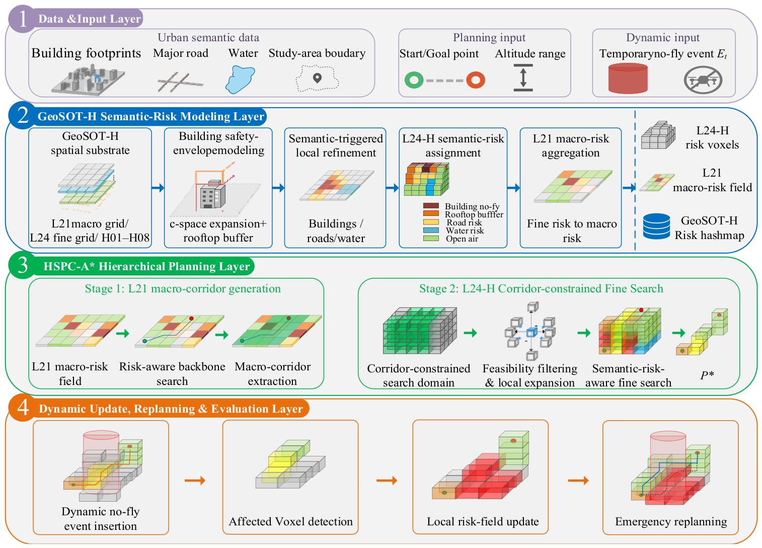
To address this problem, a GeoSOT-H-based semantic-risk field and HSPC-A* hierarchical path-planning framework is proposed. As shown in Figure 2, the framework includes four components: data input, semantic-risk modeling, hierarchical path planning, and dynamic update with emergency replanning. Building, road, water, study-area boundary, start and goal, altitude-range, and temporary no-fly-event data are encoded within a unified GeoSOT-H structure composed of L21 macro grids, L24 fine grids, and vertical H-layer codes. The resulting representation enables geometric constraints, semantic-risk attributes, altitude states, and dynamic restrictions to be queried consistently within the same spatial coding framework.
Within this structure, L21 grids represent macro-level connectivity and corridor guidance, whereas L24-H voxels retain local obstacle constraints, semantic-risk variations, and altitude-transition states. Building safety envelopes are constructed through horizontal configuration-space expansion and rooftop buffering, while semantic-triggered refinement limits L24-H voxelization to L21 cells intersecting risk-sensitive urban features. Each refined voxel is assigned a dominant semantic attribute and corresponding risk value, and the fine-level risks are subsequently aggregated through the GeoSOT parent–child relationship to construct the L21 macro-risk field. This representation distinguishes non-traversable hard constraints from traversable states with differentiated semantic-risk costs.
Based on the constructed risk field, HSPC-A* first generates a risk-guided L21 macro-corridor and then performs L24-H fine-level search within that corridor. The resulting path balances geometric length, semantic-risk exposure, vertical-maneuver cost, computational efficiency, and compliance with hard no-fly constraints. When a dynamic no-fly event intersects the original path, corridor connectivity determines whether fine-level replanning is performed within the original corridor or macro-level fallback is activated. In this way, the framework links static semantic-risk modeling, hierarchical path generation, and dynamic airspace-constraint response into a unified planning workflow for urban low-altitude UAV missions. The overall framework is shown in Figure 2.

3. GeoSOT-H-Based Semantic-Risk Airspace Modeling

3.1. GeoSOT-H Spatial Substrate and UAV Clearance-Aware Safety Envelope Construction

This study adopts GeoSOT-H to represent urban low-altitude 3D airspace. The horizontal dimension is organized using the hierarchical GeoSOT subdivision structure [21], while the vertical dimension is discretized into equally spaced height layers [23]. Each three-dimensional airspace unit is therefore identified by a horizontal GeoSOT address and a vertical height-layer code.
Coarse grids represent macro-level airspace connectivity, whereas fine voxels retain local obstacle geometry, semantic-risk differences, and altitude states. This hierarchical structure provides the common spatial basis for the macro-level and fine-level planning stages of HSPC-A*.
In the horizontal dimension, GeoSOT constructs a globally unified multi-level geographic grid system through extended longitude–latitude space and recursive quadtree subdivision. Let m denote the GeoSOT subdivision level. The angular grid sizes at different level ranges are defined in Equations (1)–(3).
C e l l 1 = 51 2 / 2 m ,   0 m 9
C e l l 2 = 64 / 2 m 9 , 10 m 15
and
C e l l 3 = 64 / 2 m 15 , 16 m 32
Let L c and L f denote the coarse and fine horizontal levels, respectively. The subdivision ratio along either horizontal direction is defined as follows:
η = 2 L f L c
where η denotes the number of fine sub-grids decomposed from one coarse grid cell along either the longitude or latitude direction.
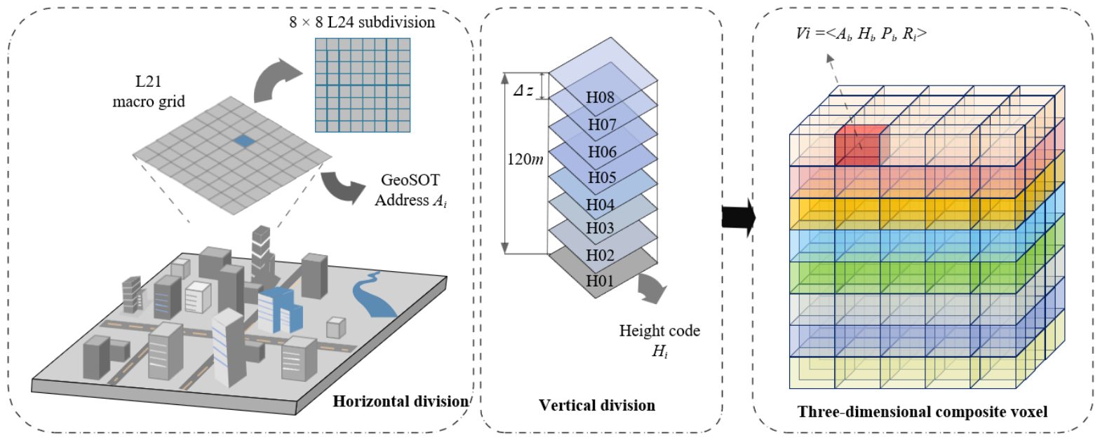
In this study, L c = 21 is selected as the macro topological level, and L f = 24 is selected as the fine level. Therefore, η = 2 24 21 = 8 , indicating that one L21 coarse grid cell can be strictly subdivided into 8 × 8 = 64 L24 fine sub-grids in the horizontal plane. This parent–child hierarchy provides a unified spatial topological basis for macro-level guidance and fine-level risk avoidance in HSPC-A*.
In the vertical dimension, equally spaced height layers are introduced to convert the continuous low-altitude space into finite search states. Let ( [ z m i n , z m a x ] ) denote the physical altitude range, and let Δ z denote the vertical resolution. The total number of height layers is defined as:
N H = z m a x z m i n Δ z
For the k-th vertical height layer, where k = 1, 2, N H , the center altitude is given by
z k c = z m i n + k 1 2 Δ z
In this study, the urban low-altitude operating range is set to 0–120 m, and the height interval is set to Δ z = 15 m. This configuration generates N H = 8 vertical height layers, encoded as H01–H08. Continuous altitude changes are thus converted into transitions between finite height layers, which supports discrete 3D heuristic search. When an L21 grid cell is fully refined, it corresponds to 8 × 8 × 8 = 512 candidate L24-H voxels. The allowable altitude range is therefore discretized into eight predefined height layers (H01–H08), each represented by its center altitude, and the mission-specified start and goal altitudes are mapped to the corresponding height layers before path search (e.g., a goal altitude of 65 m is mapped to H05 with a representative center altitude of 67.5 m).
After constructing the multi-granularity airspace substrate, physical obstacles in the urban built environment are converted into UAV clearance-aware safety envelopes. This treatment is required because a low-altitude UAV cannot be modeled as a geometric point flying exactly along obstacle boundaries. In practical urban missions, obstacle clearance is affected by UAV body size, positioning uncertainty, path-tracking deviation, and low-altitude wind disturbance. These factors are not independently estimated in this study. Instead, they are represented by a fixed composite horizontal clearance margin, denoted as r s a f e , which is used to construct conservative building safety envelopes for planning-layer path search.
r s a f e = r U A V + e p o s + e t r a c k + e w i n d
where r U A V denotes the equivalent horizontal radius of the UAV, e p o s denotes the positioning-error allowance, e t r a c k denotes the expected tracking-deviation allowance of the downstream guidance or control module, and e w i n d denotes the additional lateral-deviation allowance caused by low-altitude wind disturbance. This decomposition is used to clarify the physical meaning of the safety margin. In the experiments, these terms are not separately calibrated; instead, r s a f e is specified directly as a fixed composite parameter. According to the experimental configuration, a 2 m configuration-space expansion is applied to building footprints.
This allows the fine-level search to use a voxel-center point state while retaining conservative lateral clearance for UAV operation.
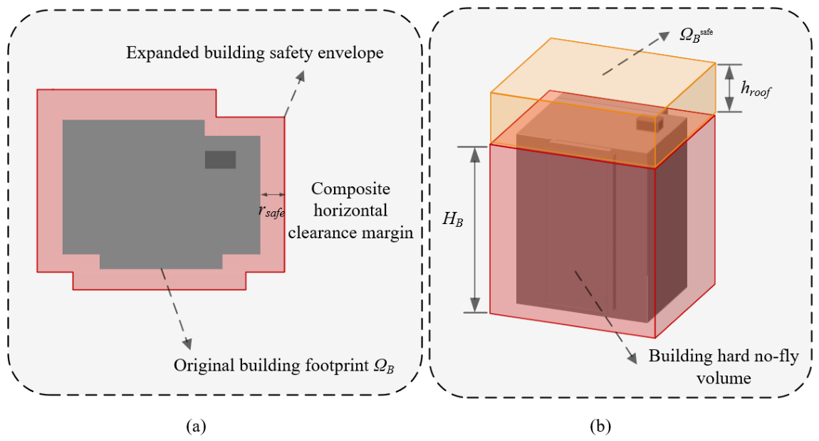
Based on the composite clearance parameter, configuration-space expansion is applied to building footprints. Let Ω B denote the original building footprint, and let K ( r s a f e ) denote an isotropic horizontal safety-buffer kernel with radius r s a f e . The expanded building safety envelope is defined as:
Ω B s a f e = Ω B K r s a f e
where K ( r s a f e ) denotes the isotropic horizontal safety-buffer kernel, denotes the Minkowski addition operator, and Ω B s a f e denotes the resulting horizontal building safety envelope.
The resulting Ω B s a f e represents the horizontal no-fly envelope around a building after considering UAV clearance requirements. Any voxel whose horizontal projection intersects this expanded envelope and whose altitude is lower than the building height is treated as a building hard no-fly voxel.
In addition to horizontal clearance, rooftop clearance is considered because UAVs flying near roof level may be affected by building-height uncertainty, rooftop facilities, vertical tracking deviation, and local turbulence. Similar to the horizontal margin, these factors are not separately estimated in the present experiment. They are represented by a fixed rooftop safety-buffer height, denoted as h r o o f . Conceptually, this buffer can be expressed as:
h r o o f =   e h e i g h t +   e v t r a c k +   e f a c i l i t y
where e h e i g h t denotes building-height uncertainty, e v t r a c k denotes vertical tracking or altitude-control deviation, and e f a c i l i t y denotes the allowance for rooftop facilities or unknown roof-level objects. In the experiments, h r o o f is specified directly as 10 m according to the parameter setting, rather than being estimated from the individual components.
The rooftop safety-buffer region is then defined as a high-risk but not absolutely blocked transition airspace:
Ω B r o o f = { v i p r o j v i Ω B s a f e , H B < z i H B + h r o o f }
where v i denotes an L24-H voxel, p r o j ( v i ) denotes its horizontal projection, z i denotes its center altitude, H B denotes the physical height of the underlying building, and h r o o f denotes the rooftop safety-buffer height.
Voxels below the physical building height are treated as hard no-fly constraints, whereas rooftop-buffer voxels are treated as traversable but high-risk states. This design allows the planner to avoid overly tight rooftop clearance while preserving feasible altitude transitions when necessary.
Therefore, the proposed safety-envelope construction should be interpreted as a planning-layer clearance approximation rather than a fully calibrated UAV dynamic safety model. The fixed 2 m horizontal C-space expansion and 10 m rooftop buffer are used to encode conservative obstacle and rooftop-clearance requirements in the GeoSOT-H risk field. This treatment is consistent with the objective of this study, which focuses on risk-aware voxel-based path planning and emergency replanning rather than low-level flight dynamics or closed-loop tracking control. The construction of the UAV clearance-aware building safety envelope is illustrated in Figure 3.
The horizontal expansion distance and rooftop buffer distance are engineering parameters used to construct conservative obstacle envelopes in the experimental environment. They are not derived from accident statistics or regulatory separation minima. The horizontal expansion accounts for map discretization, building-boundary uncertainty, and basic lateral safety margins, while the rooftop buffer mitigates near-rooftop flight in the absence of detailed rooftop-obstacle or wind-field information. Both parameters should be recalibrated for operational use according to UAV characteristics, positioning accuracy, building-data quality, local regulations, and mission-specific safety requirements.
Unlike buildings, roads and water areas generally do not form physical blocking boundaries in low-altitude airspace. Therefore, their horizontal coverage is retained as semantic influence regions, and corresponding risk attributes are assigned during semantic-risk field generation.
By integrating the horizontal GeoSOT address and the vertical H-layer code, an arbitrary GeoSOT-H composite airspace unit is defined as
V i = A i , H i , P i , R i
where A i denotes the horizontal two-dimensional GeoSOT address, H i denotes the height-layer code of the voxel, P i denotes the urban semantic attribute associated with the airspace unit, and R i denotes the risk intensity corresponding to the semantic attribute.
The resulting horizontal–altitude–planning-property representation provides the spatial position, altitude state, semantic category, and planning cost required by the subsequent risk-assignment and path-search procedures. The resulting multi-granularity GeoSOT-H representation is illustrated in Figure 4.

3.2. Semantic-Triggered Local Voxel Refinement

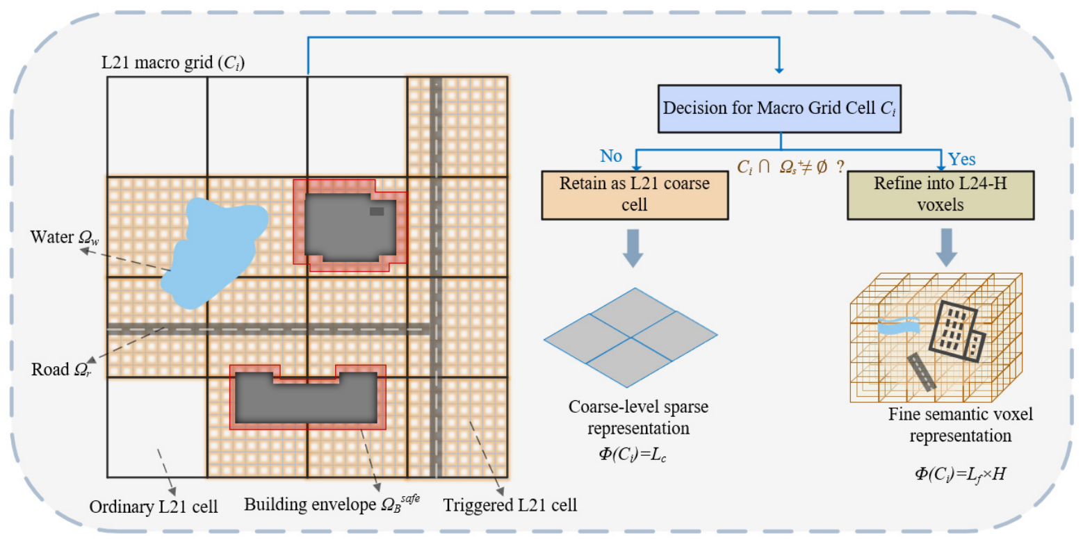
Full-domain L24-H voxelization would preserve fine spatial details but substantially increase storage and path-search complexity. Therefore, fine-resolution voxelization is triggered only for L21 cells intersecting semantic-sensitive urban objects.
Let C i denote a coarse GeoSOT grid cell, and let Ω s + denote the horizontal semantic coverage set after safety-boundary processing. It is defined as:
Ω s + = Ω B s a f e Ω r Ω w
where Ω B s a f e denotes the building safety envelope after horizontal C-space expansion, and Ω r and Ω w denote the road coverage area and water coverage area, respectively.
The set of coarse grid cells triggered for local refinement is defined as
C r e f = { C i C i Ω s + }
The set C r e f identifies the L21 grid cells requiring local refinement.
For each coarse grid cell C i , the refinement mapping function is expressed as:
Φ C i = L f × H , C i C r e f L c , C i C r e f
where H denotes the set of vertical height layers.
If C i C r e f , the cell is decomposed into L24-H voxels over the allowable height layers; otherwise, it remains at the L21 level. Ordinary open regions therefore avoid unnecessary high-resolution storage, whereas semantic-sensitive regions retain fine geometric and risk information.
Building-triggered refinement preserves building boundaries and rooftop-buffer states, while road- and water-triggered refinement retains non-blocking semantic-risk boundaries. When several semantic objects overlap within the same L21 cell, the cell is refined once, and the dominant voxel-level semantic class is subsequently determined by the priority rule in Section 3.3.
The resulting airspace model is a nonuniform multigranularity structure composed of coarse ordinary regions and refined semantic-sensitive regions. This strategy preserves the spatial detail required for risk-aware planning while reducing the redundant state expansion associated with full-domain L24-H voxelization.
The semantic-triggered local voxel-refinement process is illustrated in Figure 5.

3.3. UAV-Oriented Cross-Scale Semantic-Risk Field Generation

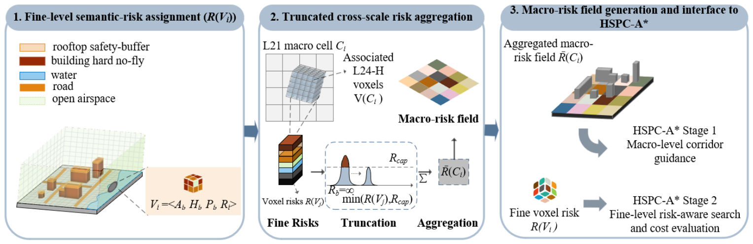
After local refinement, each L24-H voxel is assigned a dominant semantic attribute and a corresponding UAV-oriented planning cost. The resulting fine-level risks are subsequently aggregated through the GeoSOT parent–child relationship to construct the L21 macro-risk field.
The semantic-risk value represents an ordinal operational cost rather than a calibrated accident probability. It combines hard feasibility constraints and soft avoidance preferences associated with building occupancy, rooftop clearance, road-related third-party exposure, water-related operational preference, and ordinary open airspace.
Five semantic classes are considered: expanded building hard no-fly zones, rooftop safety buffers, roads, water areas, and ordinary open airspace. Building hard no-fly voxels are non-traversable, whereas the remaining classes are traversable states with differentiated soft-risk costs. Dynamically inserted no-fly voxels are treated in the same manner as building hard no-fly voxels.
The horizontally expanded building envelope below or at the corresponding building height is incorporated into the hard no-fly class rather than being treated as an additional traversable risk class. Rooftop buffers represent high-risk transition states above buildings, road voxels represent elevated third-party exposure, water voxels represent lower-priority operational concerns, and ordinary open-airspace voxels provide the baseline traversable cost.
Based on this mapping, the voxel-level semantic-risk function for L24-H voxels is defined as:
R v i = R b l o c k , i f   p r o j v i Ω B s a f e ,   z i H B R r o o f , i f   v i Ω B r o o f R r o a d , i f   p r o j ( v i ) Ω r R w a t e r , i f   p r o j ( v i ) Ω w R o p e n , o t h e r w i s e
where R b l o c k , R r o o f , R r o a d , R w a t e r , and R o p e n denote the risks of expanded building hard no-fly zones, rooftop safety-buffer regions, roads, water areas, and ordinary open airspace, respectively. Here, p r o j ( v i ) denotes the horizontal projection of voxel v i , z i denotes the voxel-center altitude, Ω R and Ω W denote the road and water coverage areas, respectively, and Ω B s a f e and Ω B r o o f follow the definitions in Section 3.1. The value R b l o c k is assigned as a non-traversable risk value and is used to identify hard no-fly voxels during path search.
The cases in Equation (15) are evaluated according to their listed priority so that an overlapping voxel cannot be assigned a lower-risk traversable category when it also satisfies a higher-priority safety condition. The corresponding hierarchy is
R b l o c k > R r o o f > R r o a d > R o p e n > R w a t e r
This priority rule distinguishes three planning states: non-traversable voxels, high-risk but traversable transition voxels, and lower-risk traversable cruising voxels. It thereby extends the airspace representation beyond a binary obstacle map without weakening hard no-fly enforcement.
The unified risk field serves different functions at the two planning scales. At the fine level, the original L24-H risk values determine node feasibility and semantic-risk cost. At the macro level, the child-voxel risks are aggregated to guide the L21 backbone path away from regions containing a larger proportion of high-risk or blocked states.
The macro stage provides regional risk guidance and search-space compression, but it does not replace voxel-level hard-blocking checks. The final path is still generated using the original L24-H risks, altitude constraints, neighborhood-transition rules, corner-crossing restriction, and macro-corridor boundary.
To construct the L21 macro-risk field without introducing a separate risk model, the semantic-risk values assigned to L24-H voxels are aggregated upward according to the GeoSOT parent–child relationship. Let V ( C i ) denote the set of L24-H voxels associated with the parent L21 cell C i within the allowable altitude range, and let N i = | V ( C i ) | . Because one L21 cell may contain expanded building envelopes, rooftop buffers, roads, water areas, and open airspace simultaneously, neither maximum-value aggregation nor an unbounded arithmetic mean is suitable. Maximum aggregation would allow a small number of local blocked voxels to dominate the entire L21 cell, whereas an unbounded mean would be dominated by the numerical blocking flag R b l o c k = 9999 . Therefore, the following truncated mean is used:
R ¯ C i = 1 N i v j V ( C i ) min R ( v j ) , R c a p
where R ¯ ( C i ) is the aggregated risk of L21 cell C i , R ( v j ) is the semantic-risk value of its j-th L24-H voxel, and R c a p is the truncation threshold. In this study, R c a p = 50 , corresponding to the highest traversable semantic-risk level R r o o f . The value R b l o c k = 9999 remains a hard non-traversability flag in the fine-level search but is capped during aggregation to prevent it from dominating the macro cost while still reflecting local risk conditions. For an unrefined ordinary L21 cell, the macro risk is assigned as R ¯ ( C i ) = R o p e n = 5 .
A simplified example illustrates the cross-scale transfer process. Consider two adjacent L21 cells, C A and C B , with equal transition distances. Cell C A contains voxel risks { 9999 , 50 , 20 , 1 , 5 , 5 , 5 , 5 } , while all voxels in C B have risk 5 . With R c a p = 50 , the aggregated risks are R ¯ C A = 50 + 50 + 20 + 1 + 5 + 5 + 5 + 5 8 = 17.625 ,   R ¯ C B = 5 .
The value 9999 is capped only during aggregation but remains a blocking flag at the fine level. If distances are equal and λ c > 0 , then M ( C A ) > M ( C B ) , so C B is preferred in macro search. After generating the L21 path, it is expanded into a corridor K .
The resulting cross-scale relationship is bidirectional but asymmetric. In the bottom-up direction, fine-level semantic risks are aggregated to form the L21 macro-risk field. In the top-down direction, the risk-guided L21 backbone path is expanded into a macro-corridor that constrains the L24-H search domain. The aggregated macro-risk values are not reassigned to fine voxels; the fine-level search continues to use original voxel risks and hard no-fly constraints. Thus, the macro level provides regional guidance and search-space reduction, while the fine level ensures voxel-scale feasibility and risk-aware path generation.
Figure 6 illustrates this bottom-up aggregation and top-down corridor-constraining process.

4. HSPC-A*: Mission-Level Corridor Guidance and Voxel-Level UAV Path Planning

HSPC-A* uses the cross-scale relationship defined in Section 3.3: aggregated L21 risk guides macro-level backbone and corridor generation, whereas the original L24-H voxel risk determines fine-level feasibility and search cost.

4.1. Mission-Level Macro-Corridor Guidance

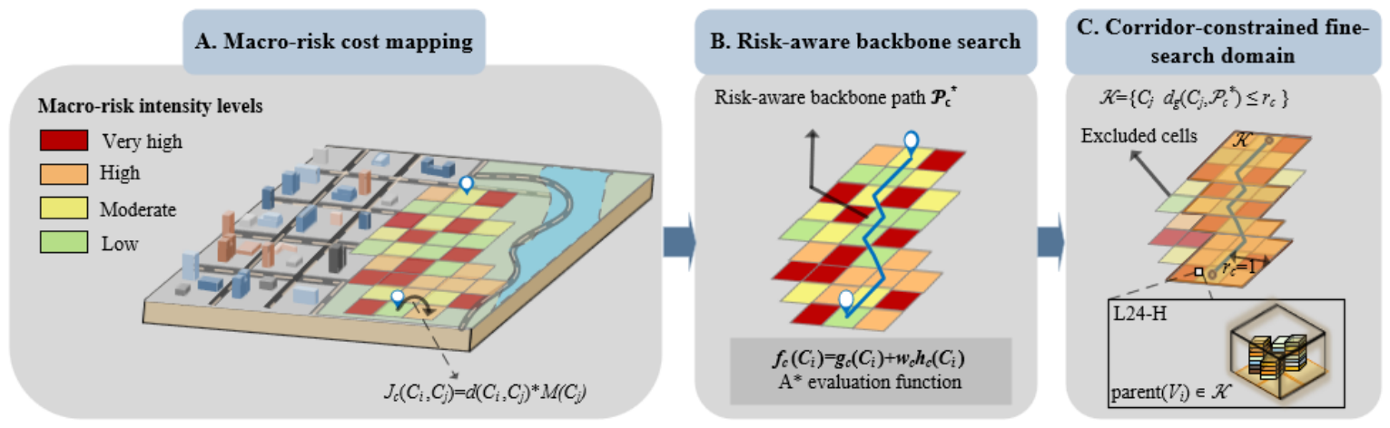
At the mission-planning level, the L21 macro grid is used to describe large-scale route connectivity and regional semantic-risk differences. For UAV missions such as logistics delivery, emergency supply transportation, and inspection, this stage generates a coarse route-guidance corridor rather than a final executable path. The macro-corridor constrains the subsequent fine-level search to a risk-guided region, thereby reducing unnecessary global exploration while preserving local maneuvering space for obstacle avoidance and altitude adjustment.
The first stage of HSPC-A* aims to generate a macro-corridor through coarse risk-topology search. This stage does not directly output the final 3D flight path. Instead, it provides a constrained search domain for the subsequent L24-H fine-level search. Specifically, the L21 horizontal macro grids are organized as a two-dimensional topological graph,
G c = ( C , E c )
where C denotes the set of L21 macro grid cells, and E c denotes the set of topological edges between adjacent L21 grid cells.
The graph adopts an eight-neighborhood topology in the horizontal plane, allowing for orthogonal and diagonal transitions between adjacent L21 cells. Each macro node retains an aggregated risk obtained from the truncated cross-scale aggregation in Section 3.3, and its geometric position is represented by the center of the corresponding L21 cell.
Given the start and goal positions, their corresponding macro grid cells are denoted as:
C s = p a r e n t ( n s ) , C g = p a r e n t ( n g )
where n s and n g denote the corresponding fine-level nodes or physical position mappings of the start and goal points, respectively.
The macro-level objective is therefore to find a low-cost backbone between the start and goal cells by jointly considering horizontal transition distance and aggregated semantic risk.
To guide the macro-level path away from high-risk regions, the aggregated risk R ¯ ( C i ) is mapped to a movement-cost multiplier. The macro edge cost from the current node C i to an adjacent node C j is defined as:
J c ( C i , C j ) = d ( C i , C j ) M ( C j )
where d ( C i , C j ) denotes the horizontal Euclidean distance between the centers of adjacent L21 grid cells, and M ( C j ) denotes the risk-cost multiplier of the target grid cell C j .
It is defined as:
M C j = c l i p 1 + λ c R ¯ ( C j ) R r e f R r e f ,   M m i n ,   M m a x
where λ c denotes the macro-risk sensitivity coefficient, R r e f denotes the mean aggregated macro-risk value of all L21 macro grid cells in the study area, and M m i n and M m a x denote the lower and upper bounds of the risk multiplier, respectively.
Equations (20) and (21) incorporate L21 macro risk into corridor generation. For adjacent cells with equal geometric distance, a higher aggregated risk R ¯ ( C j ) leads to a larger multiplier M ( C j ) and thus a higher edge cost J c ( C i , C j ) . As these costs accumulate in g c during macro A* search, the semantic-risk distribution directly influences the selected L21 backbone path.
The clipping operation bounds the multiplier, preventing extreme local values from destabilizing macro costs. L21 risk serves as soft guidance rather than a strict safety constraint. A macro cell may still be included in the backbone path even if it contains blocked voxels, since the L24-H stage can find feasible local routes or altitude adjustments. Hard constraints, such as buildings and dynamic no-fly zones, are enforced at the fine level.
After obtaining the optimal L21 backbone path P c * , neighboring cells are added via corridor dilation to form K . This preserves local maneuvering space for fine-level planning while maintaining macro-level guidance.
A risk-aware A* search is then performed on the macro-risk graph. The evaluation function is defined as:
f c ( C i ) = g c ( C i ) + w c h c ( C i )
where g c ( C i ) denotes the accumulated movement cost from the start macro grid C s to the current grid C i .
It is calculated as:
g c ( C i ) = k = 1 t J c ( C k 1 , C k )
The heuristic function h c ( C i ) is defined as the horizontal Euclidean distance from the current grid C i to the goal grid C g :
h c ( C i ) = d ( C i , C g )
The parameter w c is the heuristic weight for adjusting the goal-directed tendency of macro-level search. When w c = 1, the evaluation function corresponds to the standard A* form. When w c > 1, the search becomes more goal-directed. This may improve search efficiency at the cost of partial optimality.
The macro-level search produces a risk-guided backbone path consisting of consecutive L21 grid cells:
P c * = { C 0 , C 1 , , C m }
This backbone provides only coarse regional guidance. The final three-dimensional path is subsequently generated as an ordered sequence of L24-H voxel-center states.
To preserve sufficient lateral maneuvering space for the second-stage 3D search, the macro backbone path is expanded based on L21 adjacency. This produces the macro-corridor K , defined as:
K = { C j d g ( C j , P c * ) r c }
where r c denotes the corridor expansion radius, and d g ( C j , P c * ) denotes the minimum topological distance from grid cell C j to the macro backbone path.
It is calculated as:
d g C j , P c * = min C k P c * d g C j , C k
where d g ( C j , C k ) denotes the grid adjacency distance on the L21 topological graph.
Since an 8-neighborhood topology is adopted for corridor expansion, r c = 1 includes the backbone grid cells and their first-order 8-neighborhood cells. When r c = 2 s-order neighboring cells are further included. This expansion mechanism preserves the backbone path while providing candidate space for local detours, lateral adjustments, and altitude changes in the L24-H 3D search.
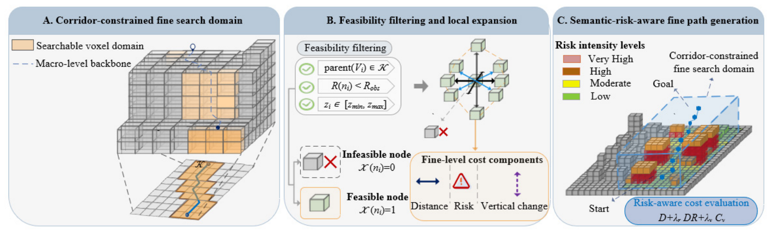
The resulting macro-corridor K serves as the interface between the two stages of HSPC-A*. Unlike the soft risk cost used at the macro level, K is treated as a hard spatial constraint in the second stage. Any voxel node V i participating in L24-H fine-level search must satisfy
p a r e n t ( V i ) K
Thus, the second-stage L24-H search is restricted to voxels whose parent L21 grid cells lie within K . The macro-level topology-planning and corridor-generation process is illustrated in Figure 7.

4.2. Fine-Level 3D Voxel Search Within the Macro-Corridor

The second stage performs voxel-level path planning within the macro-corridor generated in Section 4.1. A candidate L24-H voxel is searchable only when its parent L21 cell lies inside the corridor, its altitude is within the allowable mission range, and its risk value is below the hard-blocking threshold. Dynamically inserted no-fly voxels are treated as non-traversable states.
The fine-level search uses the original L24-H semantic-risk values rather than the aggregated L21 risks. Consequently, the semantic distinctions among rooftop buffers, roads, water areas, and ordinary open airspace are retained during final path generation. The macro risk determines where the fine-level search is conducted, whereas the voxel risk determines feasibility and path cost within that domain.
The adopted voxel connectivity is a mission-planning abstraction for hover-capable or highly maneuverable UAVs. Platform-specific constraints such as turning radius, velocity continuity, acceleration, and climb-rate limits are not incorporated at this stage and are discussed as limitations in Section 7.
The fine-level search graph is defined as
G f = ( V f , E f )
where V f denotes the set of candidate L24-H voxel nodes satisfying corridor, altitude, and risk constraints,
V f = { V i p a r e n t ( V i ) K ,   z i   [ z min , z max ] ,   R ( V i ) < R b l o c k }
where R b l o c k is the non-traversable risk threshold, mainly corresponding to building hard no-fly zones and no-fly voxels.
A voxel belongs to the candidate set only when it simultaneously satisfies the macro-corridor, altitude-range, and hard-blocking constraints.
For neighborhood expansion and cost calculation, a fine-level search node n i is defined as
n i = x i , y i , z i , R i , P i
where ( x i , y i , z i ) denotes the voxel-center coordinates derived from the L24 GeoSOT address and height-layer code. R i = R ( V i ) and P i are inherited from the voxel-level semantic-risk value and dominant semantic attribute defined in Section 3.3.
Because the building safety envelope already incorporates the adopted UAV-clearance allowances, the UAV is represented as a point state at the center of each L24-H voxel during graph search.
The node-feasibility function is further defined as:
χ n i = 1 , p a r e n t ( n i ) K ,   R ( n i ) < R b l o c k ,   z i [ z m i n , z m a x ] 0 , o t h e r w i s e
where χ ( n i ) = 1 indicates that node n i can be expanded, and χ ( n i ) = 0 indicates that the node is non-traversable.
This function encodes corridor, semantic-risk, and altitude constraints. Nodes outside K , inside non-traversable voxels, or outside the allowable altitude range are not inserted into the OPEN list.
The fine-level edge set E f is defined by local motion transitions between feasible nodes:
E f = { ( n i , n j ) n j N ( n i ) ,   χ ( n j ) = 1 }
where N ( n i ) , denotes the 3D neighborhood of node n i .
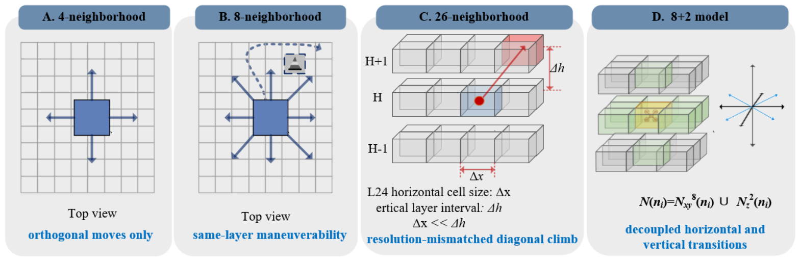
Considering the local maneuvering capability of hover-capable or highly maneuverable low-altitude UAVs, the neighborhood is defined as the union of the horizontal and vertical neighborhoods:
N ( n i ) = N x y ( n i ) N z ( n i )
The horizontal neighborhood adopts the Moore 8-neighborhood within the same height layer:
N x y ( n i ) = { n j Δ x , Δ y { 1 , 0 , 1 } ,   ( Δ x , Δ y ) ( 0 , 0 ) ,   Δ k = 0 }
where Δ k denotes the change in height-layer index.
The vertical neighborhood allows for climbing or descending to adjacent height layers at the same horizontal position,
N z ( n i ) = { n j Δ x = 0 , Δ y = 0 ,   Δ k { 1 , + 1 } }
The horizontal 8-neighborhood supports local detours within the same height layer, while the vertical neighborhood supports rooftop-buffer avoidance and altitude adjustment. For horizontal diagonal movement, if either of the two corresponding orthogonal neighboring nodes is non-traversable, the diagonal transition is considered infeasible. This prevents the path from crossing obstacle corners or corridor boundaries.
Unlike the conventional 26-neighborhood in 3D expansion, the proposed 8 + 2 neighborhood model decouples horizontal movement from vertical transitions. Horizontal expansion is performed using the 8-neighborhood, and vertical movement is allowed only between adjacent height layers at the same horizontal position. This design avoids unconstrained 3D diagonal climbing during search. It also makes altitude variation more controllable, which is consistent with the requirement for stable cruising and safe height-layer transitions in urban low-altitude operations. The proposed decoupled 8 + 2 neighborhood model is illustrated in Figure 8.
The basic 3D distance from node n i to neighboring node n j is defined as:
D n i , n j = ( x i x j ) 2 + ( y i y j ) 2 + ( z i z j ) 2
In urban low-altitude logistics, emergency supply transportation, and inspection tasks, UAVs are generally expected to maintain relatively stable cruising altitudes within a constrained vertical range. Frequent large-scale climbing or descending may increase energy consumption and control burden. It may also increase the risk of conflicts with rooftop safety buffers, local obstacles, or regulated low-altitude layers. Therefore, a vertical maneuvering cost is introduced in the L24-H fine-level search to suppress unnecessary height-layer switching. This cost does not prohibit necessary climbing or descending. Instead, it prioritizes paths with smoother vertical variations among feasible candidates, thereby improving operational stability and path executability.
Based on the basic distance, the semantic-risk penalty and vertical maneuvering cost are further incorporated into the fine-level cumulative cost function:
g f ( n j ) = g f ( n i ) + D ( n i , n j ) + λ r D ( n i , n j ) R ( n j ) + λ v C v ( n i , n j )
where g f ( n i ) denotes the accumulated cost from the start node to the current node n i , R ( n j ) denotes the semantic-risk value of the target node, λ r denotes the risk-penalty weight, and λ v denotes the vertical maneuvering cost weight.
This cost function considers not only geometric distance but also semantic-risk exposure and vertical motion. The risk term guides the path away from high-risk voxels, while the vertical maneuvering cost suppresses unnecessary height changes.
The vertical maneuvering cost C v ( n i , n j ) is defined as
C v n i , n j = γ u p | z j z i | , z j > z i γ d o w n | z j z i | , z j < z i 0 , z j = z i
where γ u p and γ d o w n denote the climb and descent cost coefficients, respectively.
Only the start and goal height layers are mapped from the mission inputs before the search, as described in Section 3.1; no intermediate cruising layer or height-transition sequence is predefined. During node expansion, the decoupled 8 + 2 neighborhood defined in Equations (34)–(36) supplies feasible same-layer and adjacent-layer candidate states, and Equation (38) updates their cumulative path costs, with the vertical-maneuver cost in Equation (39) penalizing but not prohibiting vertical transitions. Consequently, the intermediate height-layer sequence is jointly determined with the horizontal route during the L24-H A* search and forms part of the recovered three-dimensional path, rather than being assigned in a separate post-processing step.
The fine-level A* evaluation function is defined as:
f f ( n i ) = g f ( n i ) + w f h f ( n i )
where w f denotes the fine-level heuristic weight, and h f ( n i ) denotes the 3D heuristic distance from the current node to the goal node n g .
It is defined as:
h f ( n i ) = D ( n i , n g )
when w f = 1 , the evaluation function corresponds to the standard A* form. When w f > 1 , the search is more strongly guided toward the goal. This improves search efficiency but may sacrifice part of path optimality.
The final 3D discrete path generated in the fine-level search is represented as:
P * = { n 0 , n 1 , , n q }
Its optimization objective is expressed as:
P * = a r g m i n P i = 1 q [ D ( n i 1 , n i ) + λ r D ( n i 1 , n i ) R ( n i ) + λ v C v ( n i 1 , n i ) ]
subject to
p a r e n t ( n i ) K , R ( n i ) < R b l o c k ,   z i [ z m i n , z m a x ]
Therefore, the second stage outputs an L24-H voxel-center path that satisfies the macro-corridor, altitude, and semantic-risk constraints. The resulting path is represented by an ordered sequence of feasible L24-H voxel-center nodes satisfying the corridor-membership, altitude-range, hard-blocking, and neighborhood constraints in Equations (42)–(44).
Figure 9 illustrates the corresponding corridor-constrained fine-level search mechanism, including search-domain construction, candidate-node filtering, local neighborhood expansion, and semantic-risk-aware cost evaluation.
Based on the macro-level corridor construction and fine-level search formulation above, Algorithm 1 summarizes the complete two-stage HSPC-A* procedure. Stage 1 generates a risk-guided L21 macro backbone and expands it into a macro-corridor, whereas Stage 2 performs corridor-constrained A* search over feasible L24-H voxel-center states.
Algorithm 1. HSPC-A*: Hierarchical Semantic-Risk-Aware Path Planning with Corridor-Constrained A*
Input: Macro graph G c ; L24-H voxel field V ; macro risk R ¯ ( C ) ; voxel risk R ( V ) ; start and goal nodes n s , n g ; allowable altitude range [ z m i n , z m a x ] ; blocking threshold R b l o c k ; corridor radius r c ; cost parameters w c , w f , λ r , λ c , λ v .
Output: Feasible L24-H voxel-center path P * , or FAILURE.
Stage 1: L21 macro-level search and corridor generation
1 C s p a r e n t ( n s ) , C g p a r e n t ( n g )
2 P c * M a c r o A S t a r ( G c , C s , C g , J c , f c = g c + ω c h c )
3if  P c * = ∅ then return FAILURE
4 K { C j C d g ( C j , P c * ) r c }
Stage 2: Corridor-constrained fine-level search
5 V f { V i V | p a r e n t ( V i ) K , z i [ z m i n , z m a x ] , R ( V i ) < R b l o c k }
6if  n s V f or n g V f  then return  F A I L U R E
7 g f ( n ) , n V f ; g f ( n s ) 0
8 O P E N f n s ; π f
9 f f ( n s ) ω f h f ( n s )
10While  O P E N f  do
11     n i E x t r a c t M i n ( O P E N f , f f )
12    if  n i = n g  then return RecoverPath ( n g , π f )
13    end if
14    for each  n j N 8 + 2 ( n i )  do
15        if  χ ( n j ) = 0  or DiagonalRuleViolated ( n i , n j )  then continue
16         g n e w g f ( n i ) + D ( n i , n j ) + λ r D ( n i , n j ) R ( n j ) + λ v C v ( n i , n j )
17        if  g n e w < g f ( n j )  then
18             g f ( n j ) g n e w , π f ( n j ) n i
19             f f ( n j ) g f ( n j ) + ω f h f ( n j ) ; InsertOrDecreaseKey ( O P E N f , n j , f f ( n j ) )
20        end if
21    end for
22end while
23return FAILURE

5. Dynamic Airspace Constraint Insertion and Mission-Level Replanning

For urban low-altitude UAV missions, dynamic airspace constraints may arise from temporary flight restrictions, emergency control zones, local airspace occupancy, sudden obstacle-related restrictions, or mission-safety requirements. Such constraints may invalidate a previously planned path and require rapid mission-level emergency replanning. In this study, a dynamic no-fly event is modeled as a local time-varying hard constraint that can be inserted into the existing GeoSOT-H semantic-risk field.
The proposed dynamic update mechanism operates at the planning layer. It does not reconstruct the full 3D airspace model and does not perform low-level collision avoidance control. Instead, it converts the dynamic no-fly event into an affected GeoSOT-H voxel-code set, updates the corresponding local risk attributes, detects whether the original path intersects the updated no-fly region, and triggers HSPC-A* emergency replanning when necessary. This design supports rapid path updating for UAV missions under changing low-altitude airspace constraints.

5.1. Dynamic No-Fly Event Representation and Risk-Field Insertion

A dynamic no-fly event is represented as a temporary airspace constraint with both horizontal and vertical extents. In UAV mission planning, such an event may correspond to a temporary control zone, emergency rescue airspace, local conflict area, or newly restricted low-altitude region. Let the horizontal geometric domain of the dynamic no-fly event at time t be Ω E ( t ) , and let its vertical influence range be [ z E m i n , z E m a x ] . The event semantic attribute is denoted by α E , and its event risk value is denoted by R E . Since the event represents a temporary no-fly constraint, R E is assigned as a non-traversable risk value and is treated as a hard constraint during path search.
For any L24-H voxel V i , let f o o t p r i n t ( V i ) denote its horizontal projection, and let Z ( H i ) denote the physical altitude interval corresponding to the height-layer code H i . The set of L24-H voxels affected by the event is defined as
V E ( t ) = V i f o o t p r i n t ( V i ) Ω E ( t ) ,   Z ( H i ) [ z E m i n , z E m a x ]
where V E ( t ) denotes the set of event-affected L24-H voxels.
For any voxel affected by the dynamic no-fly event, its risk value and semantic attribute are updated as
R t ( V i ) = R E , P t ( V i ) = P E , V i V E ( t )
where R t ( V i ) and P t ( V i ) denote the updated risk value and semantic attribute at time t , respectively.
For voxels not affected by the event, the original semantic-risk value is retained:
R t ( V i ) = R ( V i ) , V i V E ( t )
where R ( V i ) denotes the original semantic-risk value before event insertion.
This modeling approach does not change the hierarchical structure or spatial topology of the GeoSOT-H grid. It only updates the risk attributes of event-affected voxels. Therefore, dynamic airspace constraints can be inserted into the existing 3D semantic-risk field through local risk-field updates.

5.2. GeoSOT-H Code-Based Event Update and Affected Path Detection

To avoid voxel-by-voxel geometric intersection checking over the full L24-H domain, the dynamic no-fly event update is transformed into a GeoSOT-H code-set matching problem. First, the horizontal event domain Ω E ( t ) is mapped to the affected L24 horizontal grid-code set:
G E 24 ( t ) = G p , q 24 G p , q 24 Ω E ( t )
where G p , q 24 denotes an L24 horizontal grid indexed by ( p , q ) .
Meanwhile, the affected height-layer set is generated according to the vertical influence range of the event:
H E ( t ) = H k Z ( H k ) [ z E m i n , z E m a x ]
The corresponding 3D GeoSOT-H code set affected by the event is then expressed as:
C E ( t ) = { ( G p , q 24 , H k ) G p , q 24 G E 24 ( t ) , H k H E ( t ) } .
During dynamic updating, only the L24-H voxels corresponding to C E ( t ) are modified. This mechanism converts event insertion from geometric traversal into code-set matching, thereby reducing the computational cost of local no-fly event updates.
After the dynamic no-fly event is inserted, the original static path defined in Equation (42) needs to be checked for conflicts. For each L24-H voxel-center node n i P * , its corresponding GeoSOT-H code is denoted by C ( n i ) . The path-conflict detection function is defined as:
δ P * , Ω E t = 1 , n i P * ,   C ( n i ) C E ( t ) , 0 , o t h e r w i s e .
when δ ( P * , Ω E ( t ) ) = 0 , the original path does not pass through event-affected voxels and remains feasible. When δ ( P * , Ω E ( t ) ) = 1 , the original path is affected by the dynamic no-fly event, and emergency replanning is required.
To quantify the influence of the event on the original path, the affected path length is further defined as:
L E = i = 1 q I C ( n i 1 ) C E ( t ) C ( n i ) C E ( t ) D n i 1 , n i
where I ( ) denotes the indicator function.

5.3. HSPC-A* Replanning Under Updated No-Fly Constraints

When a dynamic no-fly event occurs, the affected airspace is encoded as a set of L24-H voxels and inserted into the existing semantic-risk field as a hard constraint. Let V E ( t ) denote the set of L24-H voxels affected by the event at time t . The corresponding blocked-code set is defined as:
B E ( t ) = ( p , q , k ) V p , q , k V E ( t )
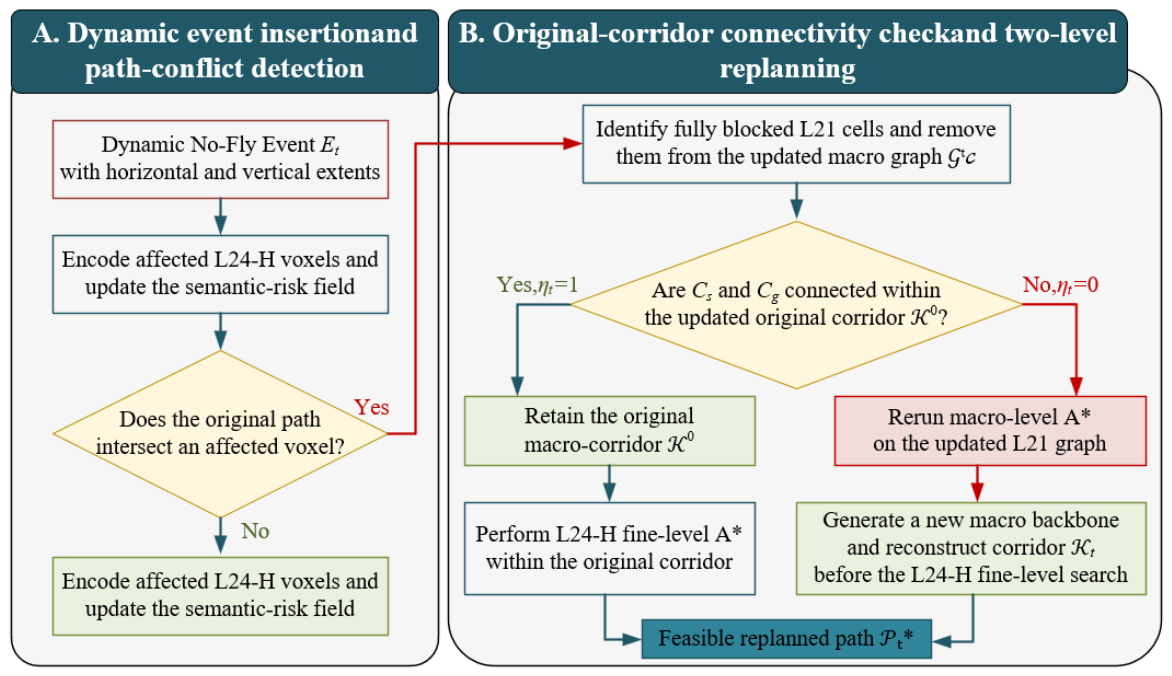
The GeoSOT-H codes of the original path nodes are compared directly with B E ( t ) . If the original path does not intersect the event-affected voxel set, the original path remains valid, and no replanning is required. If an intersection is detected, the local risk field is updated, and the connectivity of the original L21 macro-corridor is evaluated before selecting the replanning level.
For each L21 cell C , the set of feasible L24-H child states remaining after insertion of the dynamic event is defined as:
V f r e e ( C , t ) = { V c h i l d ( C ) z ( V ) [ z m i n   , z m a x   ] , R t ( V ) < R b l o c k , V V E ( t ) }
where c h i l d ( C ) denotes the set of L24-H states contained in L21 cell C , z ( V ) is the representative altitude of voxel V , [ z m i n , z m a x ] is the allowable mission altitude range, R t ( V ) is the updated semantic-risk value, and R b l o c k is the numerical hard-blocking marker used to identify non-traversable voxels.
An L21 cell is considered fully blocked when none of its L24-H child states within the allowable altitude range remain feasible. The set of fully blocked L21 cells is therefore defined as:
B 21 ( t ) = C V c V f r e e ( C , t ) =
where V c denotes the set of L21 cells in the macro-level graph. This definition prevents an L21 cell from being removed merely because some of its child voxels are affected. Macro-level blocking is activated only when no feasible fine-level state remains within that cell.
After the fully blocked L21 cells have been identified, they are removed from the macro-level graph. The updated macro graph is expressed as:
G c t = G c V c B 21 ( t ) , η t = C o n n G c t [ K 0 ] , C s , C g
Here, G c is the original L21 macro graph, K 0 is the original macro-corridor before event insertion, and G c t [ K 0 ] is the subgraph of the updated macro graph induced by the cells belonging to the original corridor. C s and C g denote the L21 cells containing the start and goal states, respectively. The connectivity indicator is defined as η t = 1 when C s and C g remain connected within the updated original corridor and η t = 0 when that connectivity is interrupted.
The macro-corridor used for dynamic replanning is then selected according to
K t = K 0 , η t = 1 , C j V c d g C j , P c , t * r c , η t = 0 .
where P c , t * is the new macro backbone generated by rerunning macro-level A* on G c t , d g denotes the grid distance from an L21 cell to the updated macro backbone, and r c is the corridor-expansion radius. Therefore, K t equals the original corridor when its updated start–goal connectivity is retained and equals the regenerated corridor when macro-level fallback is triggered.
At the fine level, whether a candidate node belongs to the dynamic no-fly region is determined by
χ E n , t = 1 , V ( n ) V E ( t ) , 0 , V ( n ) V E ( t ) .
where V ( n ) denotes the L24-H voxel associated with fine-level node (n). A node satisfying χ E ( n , t ) = 1 is treated as non-traversable and is excluded from the OPEN list during fine-level expansion.
If η t = 1 , the event is treated as a local blockage because the original corridor still provides at least one macro-level connection between the start and goal cells. In this case, the planner retains K 0 and repeats only the L24-H fine-level search within the connected original corridor. This branch avoids unnecessary macro-level reconstruction.
If η t = 0 , the fully blocked L21 cells have disconnected the original corridor. The planner therefore reruns macro-level A* on G c t , generates the updated macro backbone ( P c , t * ) , expands it according to the corridor radius r c , and obtains the regenerated corridor K t . The L24-H fine-level search is subsequently repeated within this new corridor.
Under either branch, the resulting dynamic replanning path is represented as:
P t * = n 0 t , n 1 t , , n m t
where n 0 t = n s and n m t = n g denote the unchanged start and goal states. The intermediate nodes are determined by minimizing the cumulative HSPC-A* cost in the updated semantic-risk field.
Each node in the replanned path must satisfy
n 0 t = n s ,         n m t = n g , n i + 1 t N 8 + 2 n i t ,         i = 0,1 , , m 1 , p a r e n t n i t K t ,         i = 0,1 , , m , R t n i t < R b l o c k ,         i = 0,1 , , m , V n i t V E ( t ) ,         i = 0,1 , , m .
where N 8 + 2 ( n i t ) denotes the decoupled eight-horizontal-plus-two-vertical neighborhood of node n i t , and p a r e n t ( n i t ) denotes the L21 cell containing that node. Equation (60) ensures that the replanned path remains inside the branch-dependent macro-corridor, satisfies the updated semantic-risk constraint, avoids all dynamically prohibited voxels, and follows the adopted fine-level neighborhood rule.
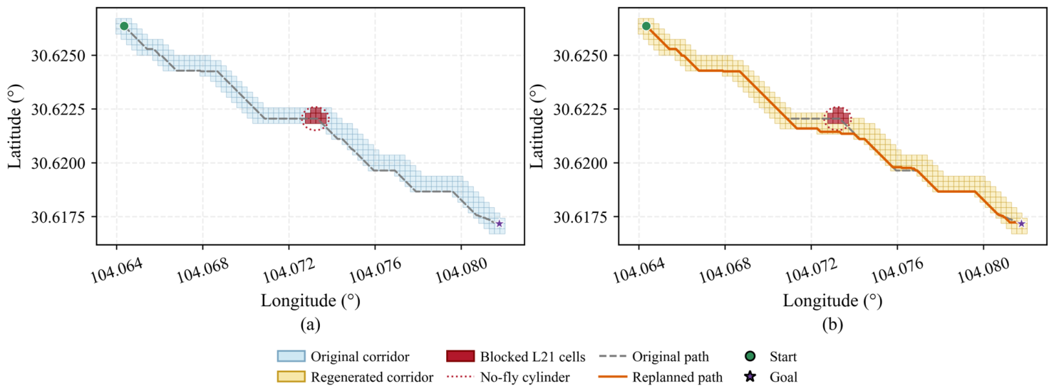
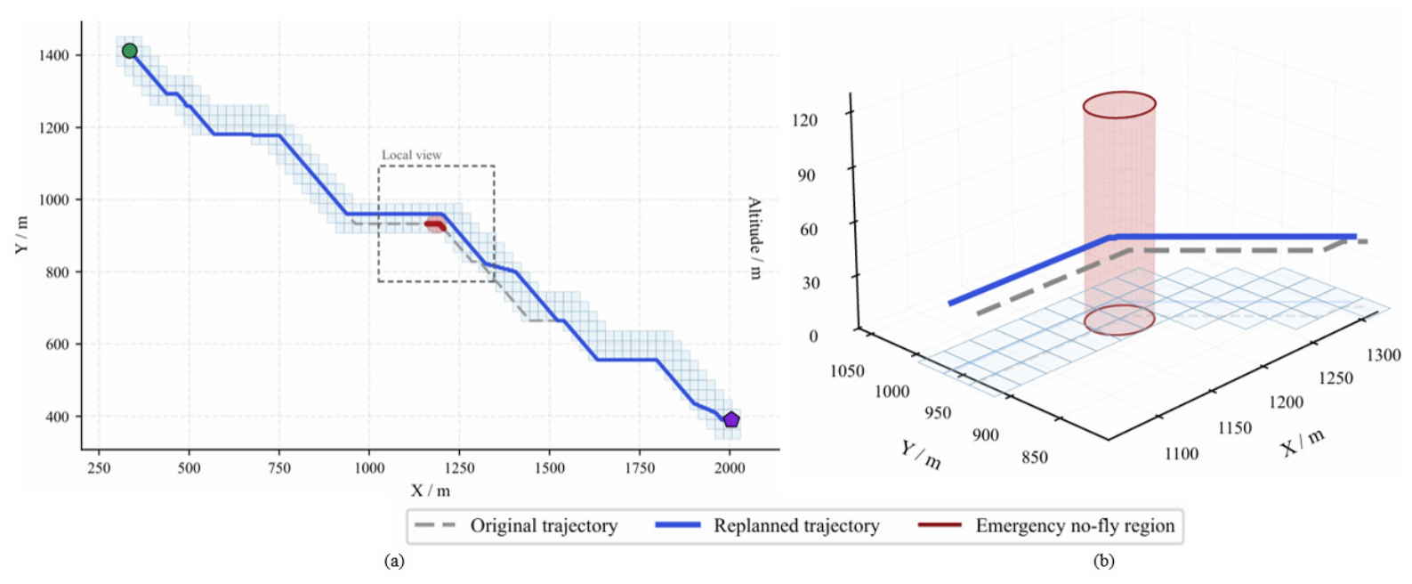
As illustrated in Figure 10, the proposed mechanism therefore contains two complementary replanning branches. When the updated original corridor remains connected, only the L24-H fine-level path is replanned within the retained corridor. When the original corridor becomes disconnected, macro-level fallback is activated, a new L21 corridor is constructed on the updated macro graph, and the fine-level search is repeated within the regenerated corridor. The replanning level is thus determined by the updated start–goal connectivity of the original macro-corridor rather than solely by whether the original path intersects the dynamic event.

6. Experiments and Evaluation

6.1. Experimental Settings

6.1.1. Study Area, Data, and Reproducibility Settings

A 2.89 km2 central urban area in Chengdu, China, containing dense buildings, major roads, and continuous water areas, was selected to evaluate the proposed GeoSOT-H representation and HSPC-A planning framework. The spatial heterogeneity of the area provides representative geometric and semantic constraints for urban low-altitude UAV path planning.
The input data comprised building footprints with height attributes, road polylines, water-body polygons, the study-area boundary, start and goal states, allowable altitude limits, and temporary no-fly-event parameters. Before GeoSOT-H modeling, all spatial datasets underwent geometry repair, duplicate removal, boundary clipping, attribute standardization, and coordinate-system harmonization.
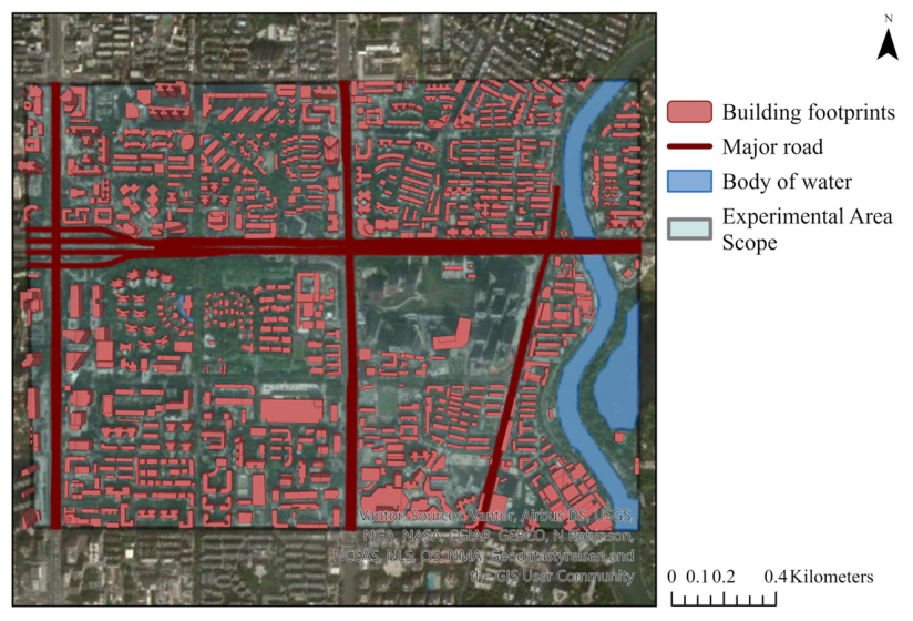
The source data were transformed into the CGCS2000 geographic coordinate system (EPSG:4490) for GeoSOT coding and spatial indexing. Metric operations, including building buffering, path-length calculation, area statistics, and distance measurement, were conducted in a projected coordinate system covering the study area. The processed features were then mapped back to the GeoSOT-H coding space for risk assignment and path search. The spatial distribution of the basic geographic data is shown in Figure 11.
All planners were evaluated using the unified protocol summarized in Table 1. For grid-search methods, including conventional 3D A and HSPC-A, the L24-H voxel centers along each path were used directly as evaluation points. For RRT* and PRM*, each path segment was uniformly resampled before the sampled points were mapped to the same L24-H semantic-risk field. This procedure ensured that geometric paths generated by different algorithm families were evaluated using consistent semantic-risk queries.
Path quality was evaluated using 3D path length, horizontal path length, and vertical maneuvering distance. Semantic-risk exposure was evaluated using average risk, maximum risk, high-risk samples, and no-fly samples. Computational performance was evaluated using search time and the number of expanded or sampled nodes, while dynamic response was evaluated using update time, affected voxels, and event-crossing length.
The average semantic risk is defined as:
R a v g = 1 N i = 1 N R i
where R a v g denotes the average semantic risk of the path, N denotes the number of path-evaluation points, and R i denotes the semantic-risk value of the i -th path-evaluation point queried from the GeoSOT-H risk hashmap.
The maximum semantic risk is defined as
R m a x = max 1 i N R i
where R m a x denotes the maximum risk value in the path-evaluation point sequence.
The number of high-risk samples is defined as:
N h i g h = i = 1 N I ( R i R h i g h ) , R h i g h = 50
where R h i g h is the high-risk threshold.
In this study, a path-evaluation point is classified as a high-risk sample when R ( v i ) R h i g h = 50 .
The workflow was implemented in Python 3.12.13 using NumPy 1.26.4, pandas 2.2.1, GeoPandas 0.14.3, Shapely 2.0.3, and Matplotlib 3.10.9. GeoPackage files stored spatial grids and visualization outputs, CSV files recorded path nodes and experimental statistics, and Python dictionary/hashmap structures supported fast queries between GeoSOT-H codes, height layers, semantic attributes, and risk values. ArcGIS Pro 3.6 was used for spatial inspection, preprocessing, and three-dimensional visualization.
All timing experiments were conducted on a desktop computer equipped with an AMD Ryzen 9 5900X 12-Core Processor (Advanced Micro Devices, Inc., Santa Clara, CA, USA), 32 GB RAM, and Windows 11 Pro 64-bit operating system (Microsoft Corporation, Redmond, WA, USA). The reported search time was measured from the start of the corresponding planning procedure to the generation of a feasible path. For HSPC-A*, the timing includes macro-corridor construction and fine-level search, while data loading, file writing, and visualization are excluded unless otherwise stated.
The source code is not publicly released at this stage because it contains project-specific preprocessing scripts and data interfaces. The experimental settings, parameter configurations, and data-structure definitions are reported to support reproducibility. The code may be made available from the corresponding author upon reasonable request, subject to project and data-use restrictions.

6.1.2. GeoSOT-H Semantic-Risk Field Construction

The experimental risk field used GeoSOT L21 as the macro level and L24-H as the locally refined fine level. The 0–120 m altitude range was divided into eight 15 m layers, H01–H08. Building footprints were horizontally expanded by 2 m, and a 10 m traversable rooftop safety buffer was constructed above each building.
Based on the voxel-level semantic-risk function defined in Section 3.3, expanded building hard no-fly zones, rooftop safety-buffer regions, roads, water areas, and ordinary open airspace were assigned different risk values. The parameter configuration is given as:
( R b l o c k , R r o o f , R r o a d , R o p e n , R w a t e r ) = ( 9999 ,   50 ,   20 ,   5 ,   1 )
The semantic-risk values used in this study are rule-based ordinal scores rather than calibrated accident probabilities. Specifically, R w a t e r = 1 , R o p e n = 5 , R r o a d = 20 , and R r o o f = 50 represent relative planning preferences among different semantic classes. A larger value indicates a stronger avoidance preference in the path-cost function, but it does not represent an empirically calibrated accident probability. The value R b l o c k = 9999 is used as a hard-blocking marker for non-traversable voxels, such as building-occupied space and dynamic no-fly areas. Therefore, 9999 should not be interpreted as a numerical risk level. The threshold of 50 is used only to identify exposure to the highest traversable semantic-risk class in the experiment.
The statistics of the constructed GeoSOT-H semantic-risk field are summarized in Table 2.
Table 2 summarizes the constructed GeoSOT-H semantic-risk field. The study area contains 5073 L21 macro grid cells, of which 3699 were refined into L24-H voxels because they intersected semantic-sensitive objects. The refined-grid ratio is 72.92%. In contrast to full-domain uniform L24-H voxelization, which would generate 2,597,376 voxels, the semantic-triggered refinement strategy explicitly stored only 426,077 risk voxels, accounting for 16.4% of full-domain voxelization. The 16.4% storage ratio reflects a substantial reduction in redundant 3D voxel storage while retaining fine-resolution representation around semantically sensitive regions. The expanded building hard no-fly voxels include the original building footprints and their horizontally expanded safety envelopes below building height. The aggregated L21 macro-risk values range from 1.00 to 44.02, providing a continuous risk gradient for macro-corridor generation.
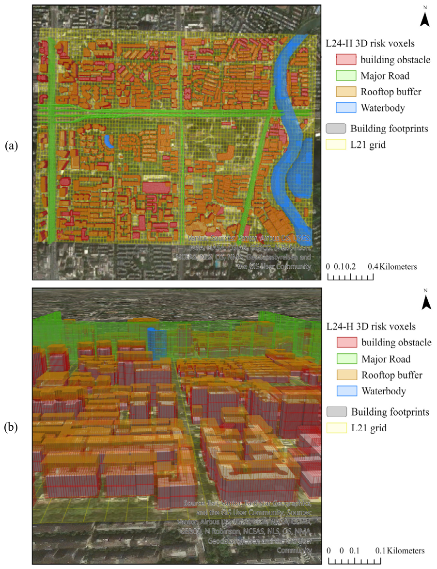
The constructed multi-granularity 3D semantic-risk field and the generated paths were visualized in the ArcGIS Pro Local Scene environment, as shown in Figure 12.

6.2. Path Planning Under Static Semantic-Risk Field

6.2.1. Comparison with Baseline Algorithms

To evaluate the path-planning performance of HSPC-A* in an urban low-altitude semantic-risk environment, static path-planning experiments were conducted using the GeoSOT-H multi-granularity semantic-risk field constructed in Section 6.1.2. All planners used the same study area, start and goal states, altitude range, L24-H risk hashmap, and hard no-fly constraints. The algorithms were compared in terms of geometric path quality, semantic-risk exposure, vertical stability, and search efficiency. The evaluated metrics included 3D path length, horizontal path length, vertical maneuvering distance, average semantic risk, maximum semantic risk, high-risk samples, and search time. The reported search time only includes the path-search process and excludes risk-hashmap loading, result export, visualization, and memory tracing.
Conventional 3D A* was tested under both the standard 26-neighborhood setting and the 8 + 2-neighborhood setting. The latter used the same adjacent-layer height-transition rule as HSPC-A*, so that the effects of macro-corridor restriction and semantic-risk-aware cost could be isolated from neighborhood connectivity. For both 3D A* settings, the search cost only included geometric movement distance, the heuristic weight was set to 1.0, and semantic-risk costs were not included. The standard 26-neighborhood result was retained as the conventional 3D A* baseline.
RRT* and PRM* were implemented as stochastic sampling-based baselines and were each run 30 times using random seeds starting from 42. RRT* used a maximum of 120,000 iterations, 10,000 post-solution optimization iterations, a step size of 40 m, a rewiring radius of 100 m, a goal sampling rate of 0.08, a goal connection radius of 45 m, and an edge-checking resolution of 5 m. PRM* used 5000 random samples, a k-nearest connection with k = max ( 20 , 3.0 log n ) , a maximum connection radius of 150 m, an edge-checking resolution of 5 m, and Dijkstra search on the constructed roadmap. For both RRT* and PRM*, sampled altitudes were snapped to the nearest height-layer center, and only hard-blocked voxels with R b l o c k = 9999 were treated as non-traversable. Their results are reported as the mean and standard deviation of 30 independent runs, whereas conventional 3D A* and HSPC-A* are deterministic algorithms and are reported using single-run results.
As shown in Table 3, the proposed HSPC-A* does not produce the shortest geometric path but achieves the lowest average semantic-risk exposure. Relative to conventional 3D A*, HSPC-A* reduces the average semantic risk by 38.8% and the search time by 97.7%, while increasing the 3D path length by only 0.89%. Both methods produce a vertical maneuvering distance of 60.00 m. RRT* obtains the shortest mean path, whereas RRT* and PRM* require substantially greater vertical maneuvering distances. Taken together, HSPC-A* offers a more balanced trade-off among semantic-risk exposure, path length, vertical stability, and computational efficiency.
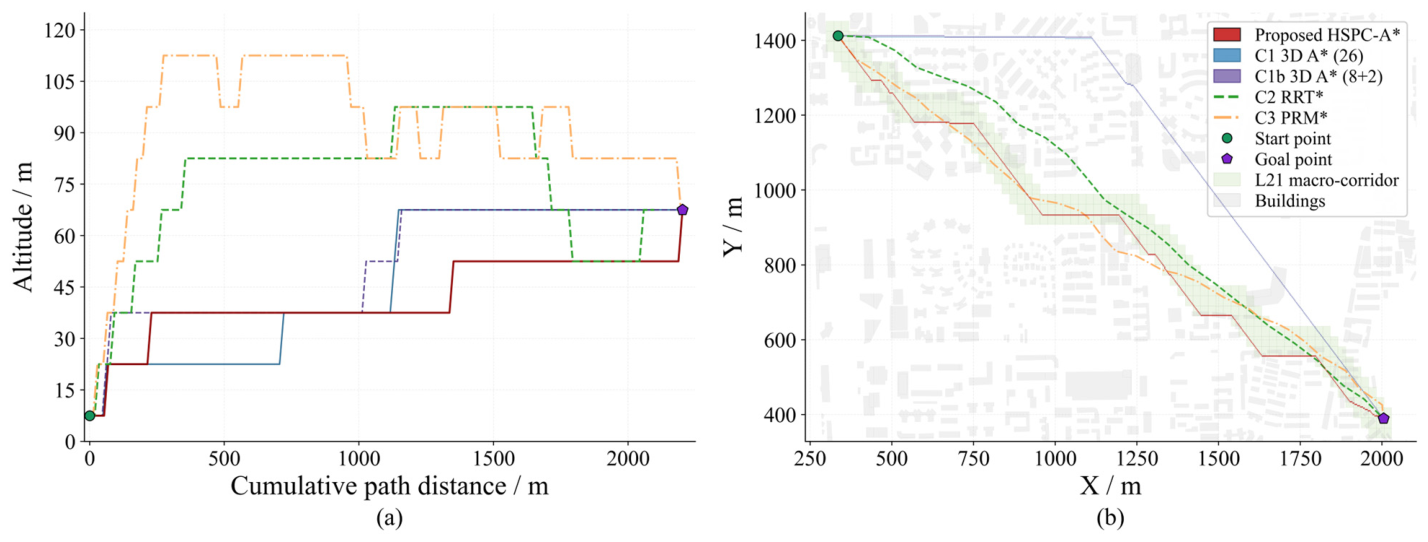
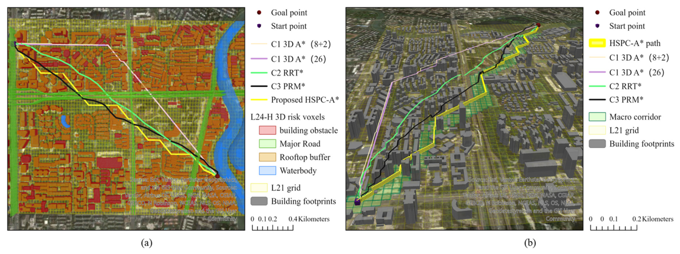
Figure 13 compares the altitude profiles and horizontal path layouts of the baseline algorithms and the proposed HSPC-A*. The altitude profiles show that HSPC-A* maintains relatively stable height changes, whereas the sampling-based methods exhibit larger altitude fluctuations. The top-view comparison shows that HSPC-A* follows the L21 macro-corridor and generates a risk-aware path without excessive horizontal detours. The stable altitude profile and controlled horizontal routing are consistent with the intended roles of the vertical-maneuver cost and macro-corridor constraint.
Figure 14 further illustrates the spatial relationship between the planned paths and the constructed semantic-risk field. In Figure 14a, the L24-H risk voxels show the distribution of expanded building hard no-fly voxels, rooftop safety-buffer regions, road-related risk voxels, and water-related risk voxels. The proposed HSPC-A* path avoids high-risk semantic regions while remaining within the risk-guided planning structure. Figure 14b shows the 3D relationship between the planned paths, building footprints, and the L21 macro-corridor. The proposed path therefore remains globally guided by the macro-corridor while retaining local flexibility for obstacle avoidance and height adjustment.

6.2.2. Additional Comparison with A*-Based Variants

To isolate the contribution of the proposed search-space organization strategy, HSPC-A* was further compared with three representative A*-based variants: Weighted A*, Hierarchical A*, and a multi-resolution planner. All methods used the same study area, start and goal states, altitude range, semantic-risk field, hard-blocking criterion, metric definitions, and 8 + 2 neighborhood setting. For hierarchical methods, both macro-level and fine-level search costs were included in the reported search time and expanded nodes.
HSPC-A* differs from these variants in how the search space is organized. Weighted A* mainly changes the heuristic priority, Hierarchical A* uses coarse-level search primarily for geometric guidance, and the multi-resolution planner changes grid resolution during search. In contrast, HSPC-A* first constructs a semantic-risk-aware macro-corridor from the GeoSOT-H risk field and then performs fine-level constrained search within the refined L24-H voxel space. Therefore, this comparison evaluates whether the proposed risk-aware hierarchical organization can reduce semantic-risk exposure while maintaining acceptable path length and computational cost. The results are presented in Table 4.
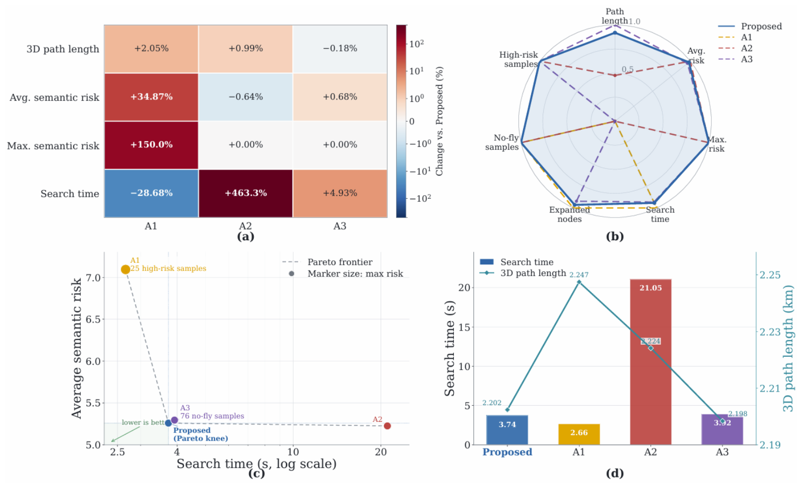
Weighted A* achieves the lowest computational cost but also produces the highest average and maximum semantic risk. Hierarchical A* and the multi-resolution planner improve geometric optimality but still suffer from relatively high semantic-risk exposure and large search overhead due to extensive node expansion. In contrast, HSPC-A* achieves a more balanced performance: although its path length is slightly higher than the best geometric result, it significantly reduces average and maximum semantic risk while also lowering node expansions and search time compared with the other structured A*-based methods. Overall, the risk-aware hierarchy achieves lower semantic-risk exposure without excessive computational cost in this comparison.

6.3. Mechanism Verification

To further verify the contribution of key components and the robustness of the main parameters, ablation and parameter-sensitivity experiments were conducted.

6.3.1. Ablation of Key Components

The complete HSPC-A* consists of the L21 macro-corridor constraint, L24-H fine-risk query, semantic-risk cost, and expanded building hard no-fly constraints. Three ablation variants were designed to evaluate the contribution of each component. The w/o risk cost variant removes the semantic-risk cost and retains only the hard no-fly constraints. The w/o macro-corridor variant removes the L21 macro-corridor constraint and adopts the bounding window of the start and goal points as the fine-level search boundary. The L21-risk-only variant uses only the parent-level L21 macro risk and does not query the L24-H fine-risk voxels. The ablation results are shown in Table 5.
Table 5 differentiates the roles of the three components. Removing the semantic-risk cost increases the average semantic risk from 5.2595 to 7.0936, raises the maximum semantic risk from 20.0 to 50.0, and produces 25 high-risk samples; geometric distance and hard no-fly constraints alone are therefore insufficient to avoid rooftop safety buffers and other high-risk voxels. Removing the L21 macro-corridor leaves risk exposure unchanged but increases the expanded nodes from 61,472 to 362,685 and the search time from 3735.93 to 21,046.08 ms. The macro-corridor therefore functions primarily to restrict the fine-level search space. The 76 no-fly samples produced by the L21-risk-only variant in the L24-H post-evaluation highlight the limitation of parent-level macro risk in guaranteeing voxel-level safety. The semantic-risk cost, macro-corridor constraint, and L24-H fine-risk query thus play complementary roles in balancing path safety and search efficiency.
Figure 15 provides a multi-perspective comparison of the ablation variants. Removing the semantic-risk cost is mainly associated with increased risk exposure, whereas removing the L21 macro-corridor primarily increases search time. In the normalized radar plot, HSPC-A* maintains a comparatively balanced profile across path length, semantic-risk exposure, no-fly avoidance, expanded nodes, and search time. The higher post-evaluation risk of the L21-risk-only variant further underscores the need for fine-level voxel risk queries. The three components therefore address distinct aspects of path safety and search efficiency.

6.3.2. Parameter Robustness and Sensitivity Analysis

To examine the robustness of HSPC-A* to parameter variations, the sensitivity analysis covered three aspects. The first involved the search-cost parameters, including the risk-cost coefficient λ r and heuristic weight w f . The second examined the semantic-risk value structure using compressed, baseline, and expanded ordinal configurations. The third considered the spatial-representation parameters, including the horizontal building-envelope expansion distance r s a f e , rooftop buffer distance h r o o f , and vertical resolution Δ z . A single-factor design was adopted throughout: only the parameter or risk-value structure under examination was varied, while all other settings were kept at their baseline values. The hard-blocking marker R b l o c k = 9999 remained unchanged in all tests.
The risk-cost coefficient λ r controls the contribution of semantic-risk cost to the path cost. Its effects were evaluated using path length, average and maximum semantic risk, expanded nodes, and search time.
As shown in Table 6 and Figure 16, introducing the risk-cost term substantially reduces semantic-risk exposure. When λ r increases from 0 to 0.01, the average semantic risk decreases from 7.1215 to 5.2595, and the maximum risk decreases from 50.0 to 20.0. Further increases in λ r provide only marginal additional risk reduction but substantially increase the number of expanded nodes and search time. Therefore, λ r = 0.01 is retained as the baseline setting within the tested range, representing a practical compromise between semantic-risk avoidance and search complexity.
The heuristic weight w f controls the goal-directed tendency of the search. Its sensitivity results are reported in Table 7.
Table 7 and Figure 17 show that increasing w f reduces search time and node expansion by strengthening goal-directed search. From w f = 1.0 to w f = 1.2 , search time decreases from 8335.15 to 3735.93 ms, while the maximum semantic risk remains 20.0. When w f 1.4 , however, the maximum semantic risk increases to 50.0, and the path becomes longer, indicating reduced risk-aware exploration. Consequently, w f = 1.2 is retained as the baseline setting within the tested range.
To evaluate the influence of the assigned semantic-risk values, three ordinal structures were tested: compressed (1, 3, 10, 30), baseline (1, 5, 20, 50), and expanded (1, 7, 30, 80), corresponding to ( R b l o c k , R r o o f , R r o a d , R o p e n , R w a t e r ) . In all tests, R b l o c k = 9999 , λ r = 0.01 , and the remaining parameters were unchanged. Each configuration was executed once for warm-up and then 20 times for timing statistics. Path metrics were obtained from the first successful measured run, while search time was reported as the mean ± standard deviation over the 20 measured runs.
For consistent comparison, all resulting paths were reevaluated using the baseline risk values, with R h i g h = 50 defining high-risk exposure. The results are presented in Table 8.
All configurations generated feasible paths with the same vertical maneuvering distance of 60 m. However, the compressed structure produced 4.482 m of high-risk exposure and increased the path length and average risk by 1.84% and 1.25%, respectively, relative to the baseline. High-risk exposure occurred only under the compressed structure, suggesting that insufficient separation between risk classes weakens high-risk-region avoidance.
Compared with the baseline, the expanded structure reduced path length and average risk by only 0.083% and 0.485%, while increasing expanded nodes by 8.97% and search time by 20.52%. Therefore, the baseline structure (1, 5, 20, 50) was retained as a balanced study-specific setting. These values represent ordinal planning penalties rather than calibrated probabilities or universally optimal parameters.
Beyond these two search-process parameters, additional tests were conducted for the spatial-representation settings. The horizontal expansion distance r s a f e is a planning-level safety envelope rather than the physical radius of the UAV. It accounts for the combined effects of grid discretization, building-footprint uncertainty, UAV positioning error, and small path-tracking deviations. The rooftop buffer h r o o f defines a traversable high-risk semantic zone above buildings, discouraging routes from passing immediately above rooftops without treating the entire buffer as a hard obstacle. The vertical resolution Δ z determines the number of altitude layers used to represent the 0–120 m airspace.
The values of r s a f e and h r o o f were not uniquely derived from a specific UAV platform or regulatory requirement. They were introduced as planning-level approximations considering the task scale, spatial-data resolution, building-data accuracy, and required safety margins. Their effects were examined over r s a f e ( 1 , 2 , 3 ) m, h r o o f ( 5 , 10 , 15 ) m, and Δ z ( 10 , 15 , 20 ) m.
As shown in Table 9, the three spatial-representation parameters produce physically interpretable changes, while the principal planning outcomes remain comparatively stable within the tested ranges. Increasing r s a f e from 1 m to 3 m increases the minimum 3-D building clearance from 2.84 m to 5.36 m. The corresponding variations in path length and average semantic risk remain within 1.42% and 0.63% of the baseline, respectively. The non-monotonic rooftop-clearance values result from changes in route geometry and should not be interpreted as a direct effect of r s a f e .
Increasing h r o o f from 5 m to 15 m increases the minimum rooftop clearance from 16.50 m to 25.50 m, whereas path length and average semantic risk vary by no more than 1.00% and 0.11% from the baseline. Therefore, the rooftop-buffer setting primarily changes rooftop-clearance outcomes without substantially altering the principal route characteristics within the tested range.
Reducing Δ z to 10 m increases the number of vertical layers from 8 to 12 and the expanded nodes by 44.7%. Increasing Δ z to 20 m reduces the layer number to six and the expanded nodes by 18.7%. Meanwhile, path length and average semantic risk vary by no more than 1.00% and 0.50%, respectively. Thus, Δ z = 15 m is retained as a practical compromise between vertical representation detail and search complexity, rather than as a universally optimal resolution.
Overall, the sensitivity results show that the principal planning outcomes remain stable within the tested ranges, while the examined parameters affect different aspects of the planning process. The risk-cost coefficient λ r governs the trade-off between semantic-risk avoidance and search complexity, whereas w f primarily affects goal-directed search efficiency. Compressing the differences between semantic-risk classes weakens high-risk-region avoidance, while expanding them provides only marginal path improvements at a higher computational cost. The spatial parameters r s a f e , h r o o f , and Δ z mainly control building-envelope clearance, rooftop separation, and vertical representation complexity, respectively.
Accordingly, λ r = 0.01 , w f = 1.2 , the semantic-risk structure (1, 5, 20, 50), r s a f e = 2 m, h r o o f = 10 m, and Δ z = 15 m were retained as the baseline settings because they provided balanced safety, path, and computational outcomes within the tested ranges. These values are study-specific planning settings rather than calibrated probabilities, universally optimal parameters, or externally validated safety thresholds.
When the framework is transferred to a different environment, the semantic-risk weights and geometric safety margins should be recalibrated rather than directly reused. Semantic-risk weights can be initialized according to local land use, population exposure, obstacle characteristics, operational requirements, and available incident or expert data, and subsequently selected through route-level sensitivity analysis. Geometric safety margins should be determined independently by considering UAV dimensions, positioning and mapping errors, obstacle-model uncertainty, tracking errors, wind disturbance, and locally required separation. The parameter values adopted in this study therefore represent scenario-specific experimental settings and are not claimed to be universally optimal.

6.4. Dynamic No-Fly Events and Two-Branch Replanning

To evaluate both branches of the connectivity-driven replanning mechanism under consistent event inputs, two cylindrical temporary no-fly events were applied to the original HSPC-A* path. Scenario 1 used a radius of 25 m and intersected the fine-level path without disconnecting the original L21 corridor. Scenario 2 increased the radius in 5 m increments until the original corridor became disconnected at 60 m, thereby activating macro-level fallback.

6.4.1. Event Setting and Dynamic Grid Update

Scenario 1 was first used to compare three methods for inserting the temporary no-fly event into the existing L24-H risk field. The event risk was set to the hard-blocking value 9999, and affected voxels were assigned the dynamic no-fly semantic attribute.
The geometry-based brute-force method tests every stored L24-H voxel against the event geometry. The R-tree method first retrieves spatial candidates and then performs geometric intersection tests. The GeoSOT-H method generates the affected L24 horizontal code set, combines it with the affected height layers, and updates the corresponding L24-H codes through hashmap lookup.
As shown in Table 10, all three methods identify the same 272 affected voxels, with precision and recall equal to 1.0000. The GeoSOT-H code update requires only 30.8027 ms, compared with 3221.8404 ms for the geometry-based brute-force update and 101.6198 ms for the R-tree geometry update. This corresponds to a 104.6-fold speedup over the brute-force update without loss of update accuracy. The agreement in affected-voxel identification, together with the 104.6-fold speedup, supports efficient event-to-voxel mapping through GeoSOT-H coding.

6.4.2. Fine-Level Replanning Under Retained Original-Corridor Connectivity

Because the 25 m event does not disconnect the original macro-corridor, the planner retains the existing corridor and repeats only the L24-H fine-level search after updating the affected voxel risks. The original and replanned paths are compared in Table 11.
The original path intersects 17 event-affected voxels over an event-crossing length of 60.4149 m. After replanning, both measures are reduced to zero, confirming complete avoidance of the inserted hard constraint.
The replanned path length is 2200.55 m compared with 2202.38 m for the original path, while average semantic risk remains nearly unchanged at approximately 5.26. Search time decreases from 3735.93 ms to 3176.71 ms. Thus, the retained-corridor branch removes the path conflict without requiring macro-level reconstruction or degrading the principal path metrics.
Figure 18 shows that the replanned path bypasses the affected L24-H voxels while remaining within the connected original L21 corridor, thereby verifying the retained-corridor branch.

6.4.3. Macro-Level Fallback After Original-Corridor Disconnection

In Scenario 2, the cylindrical event radius was increased from 25 m in 5 m increments while retaining the same center and 0–120 m vertical extent. At a radius of 60 m, ten L21 cells became fully blocked, disconnecting the original macro-corridor and triggering the macro-level fallback branch.
Macro-level A* was subsequently rerun on the updated L21 graph to construct an alternative corridor. Fine-level HSPC-A* search was then performed within the regenerated corridor. The key results are summarized in Table 12.
After the original corridor became disconnected, macro-level fallback restored a feasible search space. The regenerated corridor supported an event-avoiding fine-level path without traversing any dynamically prohibited L24-H state. Fine-level search accounted for most of the total fallback time, whereas corridor-connectivity evaluation and macro-level regeneration contributed comparatively little computational overhead.
Figure 19 illustrates how the enlarged event disconnects the original corridor and activates macro-level fallback. The regenerated corridor bypasses the affected region and constrains the subsequent fine-level search, producing a feasible path around the temporary no-fly event.

7. Discussion

The performance of HSPC-A* mainly results from separating macro-level search-space organization from fine-level feasibility evaluation. Aggregated L21 risks guide the search toward lower-risk regions and restrict the fine-level search domain, whereas the original L24-H risks preserve voxel-level hard constraints and semantic differences. This hierarchical organization reduces unnecessary full-domain expansion while retaining detailed obstacle and risk checking. The resulting path is therefore not geometrically shortest, but achieves a more balanced trade-off among semantic-risk exposure, path length, vertical stability, and computational cost.
The dynamic experiments show that path conflict and macro-corridor failure should be treated as different conditions. When the updated original corridor remains connected, fine-level replanning is sufficient and avoids unnecessary macro reconstruction. When fully blocked L21 cells disconnect the corridor, macro-level fallback is required to restore a feasible search domain. This connectivity-driven decision rule enables the framework to handle both local and corridor-scale disruptions. Code-based voxel updating further reduces event-insertion overhead, although the present results do not yet establish real-time onboard performance.
The ablation results confirm that the semantic-risk cost, macro-corridor restriction, and L24-H risk query perform complementary functions: they respectively control risk exposure, search-space size, and voxel-level feasibility. The sensitivity results further show that the principal path characteristics remain stable within the tested ranges, although different parameters affect different aspects of the planning process. The value 9999 is a hard-blocking marker, whereas (1, 5, 20, 50) are ordinal planning penalties, and 50 is only the reporting threshold for the highest traversable risk class. Similarly, the 2 m horizontal expansion, 10 m rooftop buffer, and 15 m vertical resolution are study-specific settings rather than regulatory or universally optimal values. Transfer to another environment therefore requires recalibration according to UAV characteristics, spatial-data quality, local exposure conditions, positioning and tracking errors, and operational safety requirements.
The present framework remains a mission-planning method and does not explicitly model acceleration, turning radius, climb rate, velocity continuity, or other platform-specific dynamics. The generated voxel-center path therefore requires smoothing, time parameterization, collision rechecking, and dynamic-feasibility verification before flight execution. Validation is also limited to one urban area and representative temporary no-fly events. Future work will evaluate multiple urban environments and sequential or moving restrictions, incorporate platform-specific trajectory constraints, and conduct onboard and real-flight validation.

8. Conclusions

This study developed a GeoSOT-H-enabled framework integrating three components: a multigranularity semantic-risk airspace representation, a two-stage HSPC-A* planner combining risk-aware L21 corridor guidance with L24-H fine-level search, and a connectivity-driven replanning mechanism for both retained-corridor and corridor-disconnecting events.
In the tested urban scenario, semantic-triggered refinement stores 16.4% of the full-domain L24-H voxels. Relative to conventional 3D A*, HSPC-A* reduces average semantic risk from 8.5927 to 5.2595 and search time from 164.09 s to 3.74 s, with a 0.89% increase in path length. Code-based event updating achieves a 104.6-fold speedup, and both replanning branches generate paths that avoid the updated prohibited voxels. Comparisons with A*-based variants, ablation tests, and sensitivity analysis further support the complementary roles and robustness of the proposed components within the tested conditions.
These findings establish the feasibility of the proposed representation and planning mechanism under the tested conditions, but do not demonstrate universal applicability or directly executable flight trajectories. Future work will evaluate multiple urban regions, dynamic-event configurations, and unmanned aerial vehicle platforms while incorporating parameter calibration, path smoothing, trajectory generation, platform-specific dynamics, onboard implementation, and real-flight validation.

Author Contributions

Conceptualization, K.T., H.L., L.Z. and X.Z.; Methodology, H.L., L.Z. and K.T.; Software, H.L., L.Z. and M.L.; Validation, H.L., L.Z. and M.L.; Formal Analysis, H.L., L.Z. and M.L.; Investigation, H.L., M.L. and B.L.; Resources, B.L., K.T. and X.Z.; Data Curation, H.L., L.Z. and M.L.; Visualization, H.L., L.Z. and M.L.; Writing—Original Draft, H.L., L.Z. and M.L.; Writing—Review and Editing, L.Z., K.T. and X.Z.; Supervision, K.T. and X.Z.; Project Administration, K.T. and X.Z.; Funding Acquisition, K.T. and X.Z. All authors have read and agreed to the published version of the manuscript.

Funding

This research was funded by the National Key R&D Program of China, grant number 2024YFB2605205; the Open Fund Project of Sichuan Provincial Engineering Technology Research Center for Civil Aviation Flight Technology and Safety, grant number GY2024-03B; and the Fundamental Research Funds for the Central Universities, grant number 26CAFUC03042.

Data Availability Statement

The original contributions presented in this study are included in the article. Further inquiries can be directed to the corresponding author.

Conflicts of Interest

Author Bo Li was employed by China Airport Construction Group Co., Ltd. The remaining authors declare that the research was conducted in the absence of any commercial or financial relationships that could be construed as potential conflicts of interest.

References

  1. Shakhatreh, H.; Sawalmeh, A.H.; Al-Fuqaha, A.; Dou, Z.; Almaita, E.; Khalil, I.; Othman, N.S.; Khreishah, A.; Guizani, M. Unmanned aerial vehicles (UAVs): A survey on civil applications and key research challenges. IEEE Access 2019, 7, 48572–48634. [Google Scholar] [CrossRef]
  2. Mohsan, S.A.H.; Othman, N.Q.H.; Li, Y.; Alsharif, M.H.; Khan, M.A. Unmanned aerial vehicles (UAVs): Practical aspects, applications, open challenges, security issues, and future trends. Intell. Serv. Robot. 2023, 16, 109–137. [Google Scholar] [CrossRef] [PubMed]
  3. Otto, A.; Agatz, N.; Campbell, J.; Golden, B.; Pesch, E. Optimization approaches for civil applications of unmanned aerial vehicles (UAVs) or aerial drones: A survey. Networks 2018, 72, 411–458. [Google Scholar] [CrossRef]
  4. Ait Saadi, A.; Soukane, A.; Meraihi, Y.; Benmessaoud Gabis, A.; Mirjalili, S.; Ramdane-Cherif, A. UAV path planning using optimization approaches: A survey. Arch. Comput. Methods Eng. 2022, 29, 4233–4284. [Google Scholar] [CrossRef]
  5. Tang, H.; Zhu, Q.; Qin, B.; Song, R.; Li, Z. UAV path planning based on third-party risk modeling. Sci. Rep. 2023, 13, 22259. [Google Scholar] [CrossRef] [PubMed]
  6. Dong, C.; Zhang, Y.; Jia, Z.; Liao, Y.; Zhang, L.; Wu, Q. Three-dimension collision-free trajectory planning of UAVs based on ADS-B information in low-altitude urban airspace. Chin. J. Aeronaut. 2025, 38, 103170. [Google Scholar] [CrossRef]
  7. Primatesta, S.; Rizzo, A.; la Cour-Harbo, A. Ground risk map for unmanned aircraft in urban environments. J. Intell. Robot. Syst. 2020, 97, 489–509. [Google Scholar] [CrossRef]
  8. Nowakowski, M.; Mendes, J.; Berger, G.S.; Lima, J.; dos Santos, M.F.; Pereira, A.I. Vision-based traversability assessment in hostile environments using UAV RGB imagery. In Proceedings of the 2026 27th International Carpathian Control Conference (ICCC), Szilvásvárad, Hungary, 1–3 June 2026; pp. 413–418. [Google Scholar] [CrossRef]
  9. Prevot, T.; Rios, J.; Kopardekar, P.; Robinson, J.E., III; Johnson, M.; Jung, J. UAS traffic management (UTM) concept of operations to safely enable low altitude flight operations. In Proceedings of the 16th AIAA Aviation Technology, Integration, and Operations Conference, Washington, DC, USA, 13–17 June 2016; p. 3292. [Google Scholar] [CrossRef]
  10. Cohen, A.P.; Shaheen, S.A.; Farrar, E.M. Urban air mobility: History, ecosystem, market potential, and challenges. IEEE Trans. Intell. Transp. Syst. 2021, 22, 6074–6087. [Google Scholar] [CrossRef]
  11. Garrow, L.A.; German, B.J.; Leonard, C.E. Urban air mobility: A comprehensive review and comparative analysis with autonomous and electric ground transportation for informing future research. Transp. Res. Part C Emerg. Technol. 2021, 132, 103377. [Google Scholar] [CrossRef]
  12. Dong, R.; Zhang, J.; Wang, B.; Feng, C.; Jiang, J.; Tian, J. Collaborative beamforming for secure UAV swarm communications: An end-to-end MAPPO-based framework against mobile eavesdroppers. Drones 2026, 10, 409. [Google Scholar] [CrossRef]
  13. Han, C.; Huo, L.; Tong, X.; Wang, H.; Liu, X. Spatial anti-jamming scheme for Internet of Satellites based on the deep reinforcement learning and Stackelberg game. IEEE Trans. Veh. Technol. 2020, 69, 5331–5342. [Google Scholar] [CrossRef]
  14. Gibb, R. OGC Abstract Specification Topic 21—Discrete Global Grid Systems—Part 1: Core Reference System and Operations and Equal Area Earth Reference System; Open Geospatial Consortium: Wayland, MA, USA, 2021. [Google Scholar]
  15. Sahr, K.; White, D.; Kimerling, A.J. Geodesic discrete global grid systems. Cartogr. Geogr. Inf. Sci. 2003, 30, 121–134. [Google Scholar] [CrossRef]
  16. Mahdavi-Amiri, A.; Samavati, F.; Peterson, P. Categorization and conversions for indexing methods of discrete global grid systems. ISPRS Int. J. Geo-Inf. 2015, 4, 320–336. [Google Scholar] [CrossRef]
  17. Purss, M.B.J.; Gibb, R.; Samavati, F.; Peterson, P.; Ben, J. The OGC® Discrete Global Grid System core standard: A framework for rapid geospatial integration. In Proceedings of the 2016 IEEE International Geoscience and Remote Sensing Symposium, Beijing, China, 10–15 July 2016; pp. 3610–3613. [Google Scholar] [CrossRef]
  18. Bousquin, J. Discrete Global Grid Systems as scalable geospatial frameworks for characterizing coastal environments. Environ. Model. Softw. 2021, 146, 105210. [Google Scholar] [CrossRef] [PubMed]
  19. Stephen, S.; Faulk, M.; Janowicz, K.; Fisher, C.; Thelen, T.; Zhu, R.; Hitzler, P.; Shimizu, C.; Currier, K.; Schildhauer, M.; et al. The S2 hierarchical discrete global grid as a nexus for data representation, integration, and querying across geospatial knowledge graphs. arXiv 2024, arXiv:2410.14808. [Google Scholar] [CrossRef]
  20. Zhou, C.; Lu, H.; Xiang, Y.; Wu, J.; Wang, F. GeohashTile: Vector geographic data display method based on Geohash. ISPRS Int. J. Geo-Inf. 2020, 9, 418. [Google Scholar] [CrossRef]
  21. Cheng, C.; Ren, F.; Pu, G.; Wang, H.; Chen, B. Introduction to Spatial Information Subdivision Organization; Science Press: Beijing, China, 2012. [Google Scholar]
  22. Ouyang, X.; Yu, X.; Chen, Y.; Deng, G.; Liu, X. G-SEED: A spatio-temporal encoding framework for forest and grassland data based on GeoSOT. In Proceedings of the International Conference on Remote Sensing and Digital Earth, Hangzhou, China, 2025; SPIE: Bellingham, WA, USA, 2026; Volume 14054, p. 1405402. [Google Scholar] [CrossRef]
  23. Sun, G.; Xu, Q.; Zhang, G.; Qu, T.; Cheng, C.; Deng, H. An intelligent UAV path-planning method based on the theory of the three-dimensional subdivision of earth space. ISPRS Int. J. Geo-Inf. 2023, 12, 397. [Google Scholar] [CrossRef]
  24. ElSayed, M.; Mohamed, M. Robust digital-twin airspace discretization and trajectory optimization for autonomous unmanned aerial vehicles. Sci. Rep. 2024, 14, 12506. [Google Scholar] [CrossRef] [PubMed]
  25. Zhang, Y.; Nie, Y.; Liu, Y. UAV path planning based on GeoSOT grid and JPS3D optimized algorithm. In The International Archives of the Photogrammetry, Remote Sensing and Spatial Information Sciences; Copernicus Publications: Göttingen, Germany, 2025; Volume XLVIII-4/W14-2025, pp. 421–427. [Google Scholar] [CrossRef]
  26. la Cour-Harbo, A. Quantifying risk of ground impact fatalities for small unmanned aircraft. J. Intell. Robot. Syst. 2019, 93, 367–384. [Google Scholar] [CrossRef]
  27. Braßel, H.; Zeh, T.; Lindner, M.; Fricke, H. Risk-aware UAV trajectory optimization using open urban GIS data and target level of safety constraints. Drones 2025, 9, 666. [Google Scholar] [CrossRef]
  28. Feng, Q.; Zhang, H.; Tang, W.; Wang, F.; Feng, D.; Zhong, G. Digital low-altitude airspace unmanned aerial vehicle path planning and operational capacity assessment in urban risk environments. Drones 2025, 9, 320. [Google Scholar] [CrossRef]
  29. Aggarwal, S.; Kumar, N. Path planning techniques for unmanned aerial vehicles: A review, solutions, and challenges. Comput. Commun. 2020, 149, 270–299. [Google Scholar] [CrossRef]
  30. Yahia, H.S.; Mohammed, A.S. Path planning optimization in unmanned aerial vehicles using meta-heuristic algorithms: A systematic review. Environ. Monit. Assess. 2023, 195, 30. [Google Scholar] [CrossRef] [PubMed]
  31. De Filippis, L.; Guglieri, G.; Quagliotti, F. Path planning strategies for UAVs in 3D environments. J. Intell. Robot. Syst. 2012, 65, 247–264. [Google Scholar] [CrossRef]
  32. Hu, Z.; Shirinzadeh, B. Comparative analysis of UAV path planning algorithms based on RRT for 3D environment. In Proceedings of the 19th International Conference on Intelligent Unmanned Systems; Akmeliawati, R., Harvey, D., Sergiienko, N., Yang, L.J., Park, H.C., Eds.; Springer: Singapore, 2024; Volume 1248, pp. 251–263. [Google Scholar] [CrossRef]
  33. Lindqvist, B.; Patel, A.; Löfgren, K.; Nikolakopoulos, G. A tree-based next-best-trajectory method for 3-D UAV exploration. IEEE Trans. Robot. 2024, 40, 3496–3513. [Google Scholar] [CrossRef]
  34. Lu, Y.; Yan, D.; Wan, Z.; Feng, C. Conflict-free 3D path planning for multi-UAV based on jump point search and incremental update. Drones 2025, 9, 688. [Google Scholar] [CrossRef]
  35. Kavraki, L.E.; Švestka, P.; Latombe, J.C.; Overmars, M.H. Probabilistic roadmaps for path planning in high-dimensional configuration spaces. IEEE Trans. Robot. Autom. 1996, 12, 566–580. [Google Scholar] [CrossRef]
  36. Karaman, S.; Frazzoli, E. Sampling-based algorithms for optimal motion planning. Int. J. Robot. Res. 2011, 30, 846–894. [Google Scholar] [CrossRef]
  37. Roberge, V.; Tarbouchi, M.; Labonté, G. Comparison of parallel genetic algorithm and particle swarm optimization for real-time UAV path planning. IEEE Trans. Ind. Inform. 2013, 9, 132–141. [Google Scholar] [CrossRef]
  38. Bui, D.N.; Duong, T.N.; Phung, M.D. Ant colony optimization for cooperative inspection path planning using multiple unmanned aerial vehicles. In Proceedings of the 2024 IEEE/SICE International Symposium on System Integration, Ha Long, Vietnam, 8–11 January 2024; pp. 675–680. [Google Scholar] [CrossRef]
  39. Ramezani, M.; Habibi, H.; Sanchez-Lopez, J.L.; Voos, H. UAV path planning employing MPC-reinforcement learning method considering collision avoidance. In Proceedings of the 2023 International Conference on Unmanned Aircraft Systems, Warsaw, Poland, 6–9 June 2023; pp. 507–514. [Google Scholar] [CrossRef]
  40. Reijgwart, V.; Cadena, C.; Siegwart, R.; Ott, L. Efficient hierarchical any-angle path planning on multi-resolution 3D grids. In Proceedings of the Robotics: Science and Systems Conference, Los Angeles, CA, USA, 21–25 June 2025. [Google Scholar] [CrossRef]
  41. Wu, Z.; Wang, Z.; Xie, W.; Lin, Z.; Wu, Y.; Mo, Y. 3D voxel-based collaborative path planning for UAVs in urban emergency response. In The International Archives of the Photogrammetry, Remote Sensing and Spatial Information Sciences; Copernicus Publications: Göttingen, Germany, 2025; Volume XLVIII-G-2025, pp. 1573–1579. [Google Scholar] [CrossRef]
  42. Stentz, A. The focussed D* algorithm for real-time replanning. In Proceedings of the 14th International Joint Conference on Artificial Intelligence, Montreal, QC, Canada, 20–25 August 1995; pp. 1652–1659. [Google Scholar]
  43. Koenig, S.; Likhachev, M. D* Lite. In Proceedings of the AAAI Conference on Artificial Intelligence, Edmonton, AB, Canada, 28 July–1 August 2002; Volume 17, pp. 476–483. [Google Scholar]
  44. Falanga, D.; Kleber, K.; Scaramuzza, D. Dynamic obstacle avoidance for quadrotors with event cameras. Sci. Robot. 2020, 5, eaaz9712. [Google Scholar] [CrossRef] [PubMed]
  45. Deng, M.; Yang, Q.; Peng, Y. A real-time path planning method for urban low-altitude logistics UAVs. Sensors 2023, 23, 7472. [Google Scholar] [CrossRef] [PubMed]
  46. Tang, J.; Liang, Y.; Li, K. Dynamic scene path planning of UAVs based on deep reinforcement learning. Drones 2024, 8, 60. [Google Scholar] [CrossRef]
  47. Kong, X.; Zhou, Y.; Li, Z.; Wang, S. Multi-UAV simultaneous target assignment and path planning based on deep reinforcement learning in dynamic multiple obstacles environments. Front. Neurorobot. 2024, 17, 1302898. [Google Scholar] [CrossRef] [PubMed]
  48. Guo, J.; Zhou, G.; Huang, H.; Huang, C. Advancements in UAV path planning: A deep reinforcement learning approach with soft actor–critic for enhanced navigation. Unmanned Syst. 2025, 13, 1065–1084. [Google Scholar] [CrossRef]
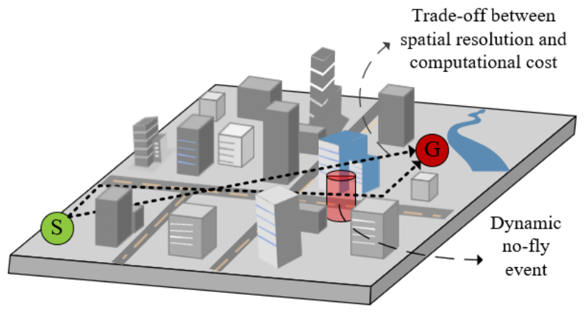
Figure 1. Problem scenario of urban low-altitude UAV path planning.
Drones 10 00603 g001
Figure 2. Overall framework of GeoSOT-H-based HSPC-A* path planning method. P* denotes the final planned three-dimensional path generated by the L24-H corridor-constrained semantic-risk-aware fine search.
Drones 10 00603 g002
Figure 3. UAV clearance-aware building safety envelope construction. (a) Horizontal C-space expansion of the original building footprint. (b) Rooftop safety buffer construction above the expanded footprint.
Drones 10 00603 g003
Figure 4. Multi-granularity GeoSOT-H representation. The colors of the stacked voxel layers are used only for visual distinction among different height layers, rather than indicating semantic-risk categories or specific risk values.
Drones 10 00603 g004
Figure 5. Semantic-triggered local voxel refinement strategy. The question mark in the decision node denotes a binary judgment on whether the current L21 macro grid cell C i intersects the semantic coverage set Ω s + . If C i Ω s + , the cell is refined into L24-H voxels; otherwise, it is retained as an L21 coarse cell.
Drones 10 00603 g005
Figure 6. Cross-scale semantic-risk field generation.
Drones 10 00603 g006
Figure 7. Macro-level topology planning and corridor generation.
Drones 10 00603 g007
Figure 8. Rationale for the proposed decoupled 8 + 2 neighborhood model. Solid arrows denote the directly allowed neighbor-expansion directions in each model, while the dashed curved arrow in panel B illustrates a same-layer detour for bypassing an obstacle rather than an additional neighbor-expansion direction.
Drones 10 00603 g008
Figure 9. Corridor-constrained fine-level 3D search mechanism in HSPC-A*.
Drones 10 00603 g009
Figure 10. GeoSOT-H-based dynamic no-fly event update, original-corridor connectivity evaluation, and two-level replanning mechanism.
Drones 10 00603 g010
Figure 11. Distribution of basic geographic data in the experimental area.
Drones 10 00603 g011
Figure 12. Semantic-triggered GeoSOT-H 3D risk field. (a) Global view. (b) Local view of L24-H risk voxels.
Drones 10 00603 g012
Figure 13. Comparison of baseline and proposed paths under the static GeoSOT-H semantic-risk field. (a) Altitude profiles. The colored lines in (a) represent the altitude profiles of different path-planning algorithms. (b) Top-view comparison.
Drones 10 00603 g013
Figure 14. ArcGIS Pro visualization of planned paths and semantic-risk constraints. (a) Top-view comparison. (b) Proposed path with buildings and macro-corridor.
Drones 10 00603 g014
Figure 15. Ablation comparison of HSPC-A* variants under the unified L24-H evaluation protocol. (a) Relative changes in path length, average semantic risk, maximum semantic risk, and search time compared with the proposed method; (b) normalized multi-metric comparison, where a larger normalized value indicates better performance; (c) risk–time relationship; (d) search time and path length comparison. A1, A2, and A3 denote the variants without semantic-risk cost, without L21 macro-corridor, and with L21 macro risk only, respectively.
Drones 10 00603 g015
Figure 16. Sensitivity analysis of the risk-cost coefficient λ r . (a) Path length and average semantic risk. (b) Search time and expanded nodes. The dashed vertical line and red marker indicate the default setting λ r = 0.01 .
Drones 10 00603 g016
Figure 17. Sensitivity analysis of the heuristic weight w f . (a) Search time and expanded nodes. (b) Heap operations. (c) Path length and risk indicators. The dashed vertical line and red marker indicate the default setting w f = 1.2 .
Drones 10 00603 g017
Figure 18. Emergency replanning under the updated no-fly constraint. (a) Original and replanned paths. (b) Local view of the dynamic no-fly event. The green and purple endpoint markers denote the start and goal points, respectively.
Drones 10 00603 g018
Figure 19. Macro-level fallback after disconnection of the original L21 corridor. (a) Original corridor blocked by the cylindrical temporary no-fly event at a radius of 60 m; (b) regenerated macro-corridor and final L24-H path.
Drones 10 00603 g019
Table 1. Evaluation protocol for path-planning and replanning experiments.
CategoryMetrics
Path quality3D path length, horizontal path length, vertical maneuvering distance
Semantic-risk exposureAverage semantic risk; maximum semantic risk; high-risk samples; no-fly samples
Search efficiencyExpanded nodes; tree/roadmap nodes; search time
Dynamic responseUpdate time; affected path length; event-crossing length
Table 2. Statistics of the constructed GeoSOT-H risk field.
ItemValue
L21 macro grids5073
Refined L21 grids3699
Refined-grid ratio72.92%
Unrefined ordinary L21 grids1374
Theoretical full L24-H voxels2,597,376
Stored L24-H risk voxels426,077
Storage ratio relative to full L24-H voxels16.4%
Expanded building hard no-fly voxels180,659
Rooftop safety-buffer voxels82,680
Road-related risk voxels41,855
Water-related risk voxels120,883
Macro-risk range1.00–44.02
Mean macro-risk9.62
Table 3. Quantitative comparison of path-planning algorithms with different search domains and neighborhood configurations under the static GeoSOT-H semantic-risk field.
MethodNeighborhoodSearch Time/ms3D Path
Length/m
Horizontal
Length/m
Vertical Maneuvering
Distance/m
Avg.
Semantic Risk
Conventional 3D A*26164,088.412183.062138.3660.008.5927
8 + 224,589.002198.362138.3660.007.3177
RRT*56,979.00 ± 12,374.982129.17 ± 23.341983.24 ± 5.09198.00 ± 33.416.5290 ± 0.9081
PRM*3988.26 ± 1217.172231.69 ± 25.942002.56 ± 7.78308.00 ± 37.096.7522 ± 1.2871
Proposed HSPC-A*8 + 23735.932202.382142.3860.005.2595
Table 4. Comparison of HSPC-A* with representative A*-based variants.
MethodSearch Time/ms3D Path
Length/m
Expanded NodesMax. Semantic RiskAvg.
Semantic Risk
Weighted A*35.722249.0188650.09.9830
Hierarchical A*5684.512195.78115,41050.07.0609
Multi-resolution planner16,637.882195.78299,72450.08.7304
Proposed HSPC-A*3735.932202.3861,47220.05.2595
Table 5. Ablation results of key components.
MethodRemoved Module3D Path Length/mAvg. Semantic RiskMax. Semantic RiskSearch Time/msExpanded NodesNo-Fly SamplesHigh-Risk Samples
Proposed HSPC-A*None2202.385.259520.03735.9361,47200
w/o risk costSemantic-risk cost2247.497.093650.02664.3550,340025
w/o macro-corridorL21 macro-corridor2224.145.225820.021,046.08362,68500
L21-risk onlyL24-H fine-risk query2198.405.295320.03920.2374,708760
Table 6. Sensitivity results of the risk-cost coefficient λ r .
Risk-Cost Scale ( λ r )Search Time/msExpanded NodesAvg. Semantic RiskMax. Semantic Risk3D Path Length/mHorizontal Length/m
0.00010,289.4550,3407.121550.02247.802187.80
0.00512,249.4659,7005.700050.02242.842182.84
0.0103735.9361,4725.259520.02202.382142.38
0.02016,352.2578,1145.234020.02200.552140.55
0.05025,328.34121,6725.235220.02192.862132.86
Table 7. Sensitivity results of the heuristic weight w f .
Heuristic Weight ( w f )Search Time/msExpanded NodesAvg. Semantic RiskMax. Semantic Risk3D Path Length/m
1.08335.15119,5615.235220.02192.86
1.16506.8092,9915.234820.02195.78
1.23735.9361,4725.259520.02202.38
1.32361.8938,4295.223520.02259.55
1.41606.0522,8235.547350.02282.64
1.51310.7418,2306.064450.02294.39
Table 8. Sensitivity of HSPC-A* to alternative semantic-risk value structures.
Risk StructureRisk Values3D Path Length/mAvg. Semantic RiskMax. Semantic RiskHigh-Risk ExposureExpanded NodesSearch Time/ms
Compressed(1, 3, 10, 30)2242.845.325050.04.482 m (0.200%)61,7892819.84 ± 190.15
Baseline(1, 5, 20, 50)2202.385.259520.0061,4722769.76 ± 150.32
Expanded(1, 7, 30, 80)2200.555.234020.0066,9853338.00 ± 150.82
Note: R b l o c k = 9999 is a hard-blocking marker and is not included in the sensitivity variation.
Table 9. Sensitivity results of spatial-representation parameters.
ParameterValue3D Path Length/mAvg. Semantic
Risk
Min. 3D Building-Prism Clearance/mMin. Rooftop Vertical Clearance (m)Expanded Nodes
Baseline r s a f e = 2   m ; h r o o f = 10   m ; Δ z = 15   m 2202.385.2604.2819.5061,472
r s a f e 1 m2233.655.2272.8431.5067,574
r s a f e 3 m2226.575.2535.3619.5066,686
h r o o f 5 m2224.455.2544.1016.5066,541
h r o o f 15 m2213.425.2574.2825.5061,826
Δ z 10 m2197.625.2344.2821.0088,951
Δ z 20 m2224.455.2554.1024.0050,003
Note: Minimum 3D clearance is the shortest distance between the densified path and the original, non-inflated building prisms, evaluated using a sampling interval not exceeding 0.5 m. Minimum rooftop clearance denotes the minimum vertical separation between the path and the building roofs. For each vertical resolution, the physical start and goal altitudes are mapped to the centers of their corresponding vertical layers.
Table 10. Dynamic no-fly event update performance using different update strategies.
MethodUpdated VoxelsUpdate Time/msPrecisionRecall
Geometry-based brute-force update2723221.84041.00001.0000
R-tree geometry update272101.61981.00001.0000
GeoSOT-H code update27230.80271.00001.0000
Table 11. Emergency replanning results under the updated GeoSOT-H risk field.
Path3D Path Length/mAvg. Semantic RiskEvent-Affected VoxelsEvent-Crossing Length/mExpanded NodesSearch Time/ms
Original path2202.38005.25951760.414961,4723735.93
Replanned path2200.55005.260000.000060,0213176.71
Table 12. Key configuration and replanning results for the macro-level fallback branch.
Evaluation ItemResult
Fully blocked L21 cells10
Affected L24 cells/blocked L24-H states1219/9752
Fine-level search/total fallback time3010.89/3731.80 ms
Regenerated corridor294 L21 cells
Final 3D path length2200.55 m
Disclaimer/Publisher’s Note: The statements, opinions and data contained in all publications are solely those of the individual author(s) and contributor(s) and not of MDPI and/or the editor(s). MDPI and/or the editor(s) disclaim responsibility for any injury to people or property resulting from any ideas, methods, instructions or products referred to in the content.