1. Introduction
Indoor urban firefighting and search operations put first responders at risk of hazards that may be deadly, including limited sightlines, exposure to toxic gases, high temperatures, and poor structural stability. Emergency and urgent operations that require rapid response with an incomplete understanding of the situation often require firefighters to traverse hazardous conditions, often forcing them to enter dangerous environments before comprehensive situational assessments can be completed. Even though protective gear and training protocols have made significant progress, injuries to firefighters and fatalities during interior operations remain stubbornly high [
1,
2].
Unmanned aerial vehicles (UAVs) have demonstrated utility in emergency response over the last decade and have been used for flammable gas detection [
3], autonomous mapping during fire incidents [
4], and emergency response training [
5]. Recent advancements in sensing, autonomy, and cost [
6,
7], have enabled effective mapping and perception on smaller, lower-cost platforms, thereby reducing barriers to adoption for municipal fire departments. However, there remains a gap between outdoor UAVs—dominating both post-incident damage assessment [
8] and large-area search operations [
5]—and cramped indoor firefighting conditions. In indoor firefighting situations, currently available UAV platforms face significant limitations. Current systems are generally larger than the available homes’ doorways, hallways, or stairwells, thereby limiting their use to specific areas where victims may be trapped. In smoke-covered areas where thermal imaging is crucial for locating victims and assessing structures, single-modality RGB sensing is insufficient [
9]. Moreover, traditional quadrotors have inadequate collision protection, and many platforms are preconfigured to require complex setup, making them unable to accommodate the rapid deployment required for emergency response. There is empirical evidence supporting the promise and highlighting the obstacles of drone technology in emergency response. Wankmüller et al. [
10] conducted 11 usability tests involving 288 rescuers from Austrian and Italian rescue organizations across 49 realistic emergency situations. They found that drones significantly enhance operational safety in search-and-rescue missions, particularly in rugged terrain and confined spaces. However, the study found that single-modality sensing did not reliably detect victims, image analysis caused cognitive overload for operators who had to control the flight simultaneously, and communication problems between drone operators and incident commanders complicated a coordinated response plan. A scoping review by Daud et al. [
8], which examined 52 studies from 2009 to 2020, further underscores these gaps. Although the number of drone applications in disaster management has grown rapidly, only 2% of the studies reviewed addressed human-made disaster scenarios such as structural fires. The authors explicitly noted that research on drone applications for victim detection in confined spaces was lacking, citing technological limitations such as limited battery capacity, restricted access to these tight spaces, suboptimal performance, and susceptibility to adverse environments. In this context, a comprehensive solution to indoor firefighting UAV design is proposed to address the reported difficulties.
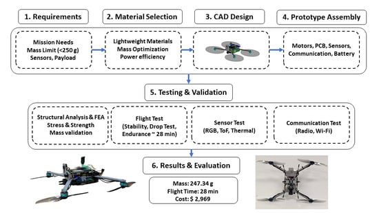
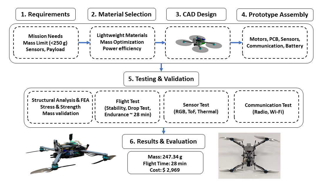
This paper presents the design and experimental evaluation of a lightweight micro-UAV platform intended for indoor emergency response applications. The system integrates concurrent RGB and thermal sensing within a protective airframe weighing 247.34 g (sub-250 g class), enabling deployment in smoke-filled and structurally complex environments encountered during firefighting and search operations. Under strict mass and power constraints, the platform is organized around four primary subsystems: (1) mass-constrained system design, achieving a total weight of 247.34 g through careful component selection, power budgeting, and structural optimization; (2) multimodal sensing using RGB and thermal imaging to improve situational awareness in low-visibility conditions; (3) onboard computation supporting sensor integration, basic autonomy, and data processing; and (4) a communication architecture combining radio telemetry with onboard video recording to maintain data availability during wireless disruptions, alongside a protective 3D-printed cage designed to balance impact resistance, lightweight construction, and manufacturability.
This work makes several key contributions. First, it presents a lightweight UAV platform specifically designed for post-fire indoor inspection by first responders, addressing the unique challenges of confined, smoke-damaged, and structurally uncertain environments. Second, it demonstrates a constraint-driven system design that enables the integration of multimodal sensing (RGB and thermal) within strict sub-250 g mass and power limitations, which is not commonly achieved in existing platforms. Third, the work provides a practical design methodology that balances sensing capability, structural protection, affordability, and deployability for real-world emergency response scenarios. Finally, the system is experimentally evaluated through subsystem-level testing, communication analysis, and structural validation, illustrating the feasibility of the proposed design.
In comparison with existing UAV platforms for emergency response, many systems exceed the sub-250 g mass threshold, which may limit their deployment in confined indoor environments such as residential structures. While prior work has demonstrated UAV capabilities in mapping, gas detection, and outdoor search operations, these systems are often designed for less constrained settings and larger platforms. In this context, the proposed system adopts a constraint-driven design approach centered on achieving a sub-250 g platform while maintaining essential sensing capabilities. The resulting UAV achieves a total system mass of 247.34 g and integrates RGB and thermal sensing within a protective airframe, aiming to support deployment in space-constrained and low-visibility conditions encountered during indoor emergency response scenarios.
2. System Requirements
The system requirements were developed based on direct feedback gathered through engagement with the Southfield Fire Department in Detroit, Michigan, and informed by operational needs observed during indoor firefighting evaluations. These requirements emphasize rapid deployment, situational awareness, environmental sensing, and operator usability under severe constraints on size, mass, and power. The following subsections describe the high-level system requirements, as well as detailed sensor, software, hardware, and operational requirements that collectively define the design space of the proposed platform.
2.1. High-Level System Requirements
The proposed system shall be a compact, lightweight unmanned aerial platform designed specifically for indoor urban firefighting and post-fire search and data collection missions to help identify high-risk areas within buildings. Emphasis is placed on minimizing system size and mass to enable safe operation in confined spaces and rapid deployment by first responders. The platform must support simultaneous RGB and thermal environment mapping to provide situational awareness in low-visibility and smoke-filled conditions.
Additional sensing capabilities, including environmental gas concentration measurement (CO2, O2, H2S, and NH3), were considered during the system design phase to assist first responders in evaluating air quality, hazard levels, and occupant survivability. However, these modalities were not integrated into the current prototype due to mass, power, and platform compatibility constraints.
All vehicle control, sensing, and visualization functions shall be accessible through a unified user interface; however, the Unreal Engine–based visualization component will be developed in future work [
11]. The system must support bidirectional audio communication between first responders and building occupants to enable real-time interaction during rescue operations. To ensure mission practicality, the platform shall provide a minimum continuous operational time of 30 min on a single battery charge. Furthermore, all applicable hardware components shall comply with Blue UAS certification requirements to ensure secure, trusted deployment in public safety contexts. The following high-level system requirements define the core functional and operational objectives of the proposed unmanned aerial platform. These requirements emphasize compactness, situational awareness, environmental sensing, endurance, and secure deployment for indoor firefighting and search missions.
2.2. Sensor Requirements
The sensor suite is designed to support navigation, mapping, hazard detection, and human interaction while remaining compatible with strict mass, power, and interface constraints imposed by a compact aerial platform.
Table 1 summarizes the primary sensing requirements considered during the system design phase based on operational needs in indoor post-fire inspection scenarios.
While multiple sensing modalities were initially considered, including gas detection and bidirectional audio communication, these were not integrated into the current prototype due to mass, power, and platform compatibility constraints. The implemented system focuses on RGB imaging, thermal sensing, and inertial measurement for flight stabilization and environmental awareness.
2.3. Software Requirements
Reliable communication between the unmanned aerial vehicle and the user interface is a critical software requirement for real-time operation in emergency response scenarios. The user interface shall be developed in Unreal Engine, which provides native integration support for the Robot Operating System (ROS). The overall system architecture shall be implemented using ROS 2 to enable modular communication, scalable sensor integration, and robust inter-process data exchange. To support full controllability and monitoring through ROS 2, the flight controller firmware shall be compatible with ROS 2 communication pipelines, such as those provided by PX4-based systems. The software stack shall support receiving flight commands from the Unreal Engine interface, aggregating and transmitting sensor data over ROS 2 topics, and fusing RGB, thermal, and distance data into a unified three-dimensional representation of the environment suitable for visualization and situational awareness.
2.4. Hardware Requirements
The hardware architecture balances compactness, endurance, robustness, and onboard computational capability within constrained mass and power budgets represented in
Table 2.
2.5. Operational Requirements
To ensure reliable deployment in emergency response environments, the system must satisfy operational and structural requirements emphasizing simplicity, durability, and mission effectiveness. The platform shall be usable by operators with little to no prior piloting experience, while still providing sufficient endurance, communication reliability, and robustness to support indoor search missions.
The system shall support rapid, throwable deployment and allow battery replacement without loss of mission data or operational state. Real-time audio and video data shall be transmitted over a wireless radio link to the operator interface. Structurally, the platform shall be capable of withstanding harsh operating conditions, including elevated temperatures, smoke, falling debris, and incidental water exposure, without catastrophic failure. The airframe and propulsion system shall be designed to survive falls or collisions with minimal, low-cost damage, and the propellers shall be protected to enhance durability and ensure operator and bystander safety.
3. Design Process
Because mass was the primary design constraint, each component’s contribution to total system mass was tracked throughout the development process. A reference micro-UAV platform, the Starling 2 [
12], was evaluated to establish baseline values for mass, center of gravity (CG), and power consumption, providing practical bounds for early component selection. Subsystem-level mass budgeting was used to define design limits, such as constraining the sensor payload to approximately 30 g, and informed both battery selection and CAD-based CG placement.
When multiple candidate components were available, a structured multi-criteria decision process was used to guide hardware selection across all major subsystems, including flight control/computing, sensors, communications, and airframe hardware. Candidate options were first screened against non-negotiable constraints such as mass and volume limits, electrical and software compatibility, ROS 2 integration feasibility, and component availability. Remaining candidates were then evaluated using a weighted feature scoring method across seven criteria: mass, affordability, durability, end-user usability, fabricability, maintainability, and assemblability. Criterion weights were derived through pairwise comparisons to reflect their relative importance under the sub-250 g indoor UAV constraint. The evaluation process was conducted by the authors, whose expertise includes robotics, embedded systems, UAV design, and software integration. Pairwise comparisons were initially performed independently and finalized through consensus discussions. In cases of disagreement or ties, decisions were resolved through majority agreement or by re-evaluating the criteria based on mission priorities.
Final selections were based on weighted total scores while also considering integration risks such as sensor compatibility, documentation maturity, and required hardware adapters.
Table 3 summarizes the component selection procedure, while detailed pairwise matrices and scoring tables for each subsystem are provided in
Appendix A.
3.1. Flight Controller and Companion Board
The flight controller (FC) was selected early in the design process due to its influence on downstream hardware and software decisions. Primary selection constraints included the need for a compact, lightweight system architecture and compatibility with ROS-based flight control stacks, such as PX4 or ArduPilot. While multiple FCs support these stacks, enforcing strict mass limits significantly reduced viable options. ROS-compatible flight control firmware manages only low-level flight functions, requiring sensing, perception, and communication tasks to be executed on a separate companion computer. Although common solutions pair a lightweight FC with an external computer (e.g., Raspberry Pi [
13]), the combined mass of additional boards, cabling, and mounting hardware proved prohibitive for the target weight class. To formalize these trade-offs, a feature-based pairwise comparison was conducted to evaluate candidate flight controllers against key selection criteria. The resulting weighted scoring, summarized in
Table A1, reflects the relative importance of mass, manufacturability, maintainability, and usability within the constraints of the target form factor.
As a result, integrated flight control and computing platforms were evaluated. Among available options, ModalAI’s VOXL 2 [
14] and VOXL 2 Mini [
15] emerged as the only viable candidates within the mass constraint. A weighted feature comparison was conducted considering mass, cost, durability, usability, fabricability, maintainability, and assemblability, with the resulting scores summarized in
Table A2. While the VOXL 2 Mini offers a lower board mass (11 g vs. 15 g), its limited sensor support and documentation significantly constrained integration flexibility. The VOXL 2 provides broader native support for RGB, thermal, and depth sensors, reducing the need for additional adapters and mitigating potential mass increases. Based on these considerations, the VOXL 2 was selected as the flight control and companion computing platform.
3.2. Perception Sensors
The UAV is designed to support simultaneous localization and mapping (SLAM) with an overlaid thermal layer, requiring an RGB camera, a thermal imager, and a distance sensor. Given the selection of the VOXL 2 as the flight control and computing platform, only sensors with verified compatibility were considered. Although USB-based sensors are supported, their reliance on breakout hardware and limited available ports increased system mass and complexity. As a result, preference was given to sensors interfacing via onboard MIPI or I2C connections to minimize mass.
For RGB imaging, two Blue UAS–certified cameras supported by the VOXL 2 were evaluated: the M0161 [
16] and M0186 [
17]. The M0161 was selected due to its lower mass (7.5 g vs. 10.5 g) and higher resolution (4K vs. 1540p), with comparable cost and form factor. Depth sensing selection was constrained by the need for sufficient point density to support SLAM under strict mass limits. Time-of-flight (ToF) sensors were identified as the most viable option in this weight class. The VOXL 2 ToF depth sensor [
18] was selected due to its high resolution (240 ×180) and native support, outperforming lightweight alternatives such as the VL53L5CX [
19], which provides significantly lower spatial resolution (8 × 8). Thermal sensing presented the greatest challenge due to competing constraints on mass, resolution, and software support. Two candidates were evaluated: the FLIR Lepton [
20] and the MLX90640 [
21]. While the Lepton offers higher spatial resolution (80 × 60), it requires additional breakout hardware, increasing total mass. The MLX90640, with a lower resolution (24 × 32) but higher frame rate (64 Hz) and minimal interfacing requirements, was favored in weighted feature comparisons represented in
Table A3.
3.3. Motors and Propellers
Based on application requirements, the maximum operational speed was constrained by sensing performance. With environment data acquired at 15 Hz and a target spatial resolution of 5 cm, the maximum allowable translational speed was limited to 0.75 m/s. Thrust-to-weight requirements were evaluated for steady lateral motion, vertical ascent, and rapid maneuvering. For lateral flight at the maximum speed and a maximum tilt angle of 20°, aerodynamic drag effects were estimated using a representative drag coefficient for micro-UAV platforms [
22], resulting in a required thrust-to-weight ratio of approximately 1.07. For vertical ascent at 1 m/s, the corresponding thrust-to-weight ratio was approximately 1.01.
To ensure sufficient responsiveness during aggressive maneuvers and transitions from hover, additional thrust margin was included. Assuming a peak acceleration of 7.5 m/s
2, the thrust-to-weight ratio requirement increased to approximately 1.76. Based on these combined constraints and to provide adequate control margin, a target thrust-to-weight ratio of 1.8 was selected for the propulsion system. An electric multirotor propulsion sizing tool [
23] was used to evaluate motor–propeller combinations meeting this criterion. Combinations yielding thrust-to-weight ratios below 1.8 were excluded. Candidate options were ranked using a weighted feature comparison considering mass, cost, current draw, and thrust (
Table A4).
The selected configuration consists of HGLRC Aeolus 1303.5–2500 KV brushless motors paired with Gemfan LR5126 5.1 × 2.6 bi-blade propellers. Each motor weighs approximately 6.5 g, and the corresponding propeller adds approximately 2.6 g, resulting in a total motor–propeller pair mass of approximately 9.1 g [
24]. While motors of this size provide limited torque for a 5-inch propeller, this configuration represents an acceptable performance–mass trade-off. The low-pitch LR5126 propeller reduces aerodynamic load, enabling efficient cruise and hover while satisfying the strict mass budget enabled by lightweight composite structural materials [
25]. This selection was further constrained by component availability, as lightweight motors with sufficient torque for 5-inch propellers are scarce in the sub-250 g class.
The motors and propellers could be mounted in either a tractor or puller configuration. The tractor configuration, with motors mounted above the frame arms, is susceptible to airflow interference caused by the arms. To mitigate this effect, the motors were mounted in a puller configuration, below the arms. Prior studies have shown that this configuration reduces airflow disruption and improves efficiency [
26,
27,
28].
3.4. Battery
The battery pack is typically the heaviest component in a UAV and therefore strongly constrains system design. Single-cell configurations were excluded due to insufficient voltage for propulsion, while higher cell counts increase mass. Battery suitability was evaluated based on mass and throughput, defined as energy capacity and continuous discharge capability, with operability considered for ease of replacement. A two-cell, 28.8 Wh battery used in the reference platform served as the baseline for comparison. No lighter commercial alternatives meeting throughput requirements were identified. Although higher-discharge options exist, their mass exceeded acceptable limits. By imposing software-based throttle limits to constrain peak current draw, the reference battery provided safe operation and achieved the highest overall score in
Table A5.
3.5. Electronic Speed Controller Selection
Electronic speed controllers (ESCs) regulate motor speed and are critical for stable and reliable flight. ESC selection was constrained by the small mass requirement and compatibility with the VOXL flight controller architecture. Both individual ESCs and integrated 4-in-1 ESC boards were evaluated. While individual ESCs offer modularity, their additional wiring and mounting hardware introduce significant mass penalties. In contrast, 4-in-1 ESCs consolidate all motor controllers onto a single PCB, reducing mass and wiring complexity, which is essential for meeting the system mass budget for sub-250 g platforms [
29].
Selection criteria were weighted based on their impact on system performance. As shown in
Table A6, current handling capability received the highest weighting (67%) to ensure reliable operation during peak load conditions, while mass was weighted at 33%. Cost was assigned a weight of 0%, as budget constraints were not limiting for this component. Using these weights, candidate ESCs were scored on a five-point scale and evaluated using a weighted scoring methodology. The averaged results for the top three candidates are summarized in
Table A7. The analysis resulted in a tie between the ModalAI 4-in-1 ESC (M0129) and ModalAI 4-in-1 ESC (M0138), both achieving a total score of 3.67, with the Holybro Tekko32 35A 4-in-1 scoring 3.33.
Although the M0138 offered superior current handling, its significantly higher mass reduced its suitability for the sub-250 g platform. The Holybro Tekko32 provided competitive performance but was heavier and lacked native VOXL integration. The ModalAI 4-in-1 ESC (M0129) achieved the highest mass rating while providing sufficient current capacity for the selected motors and propulsion system [
30]. Additionally, native VOXL compatibility simplifies integration with onboard communication and telemetry subsystems [
31]. Based on this evaluation, the ModalAI 4-in-1 ESC (M0129) was selected as the motor control solution, offering the best balance of mass efficiency, electrical performance, and system integration.
3.6. Communication System Selection
The communication system provides the link between the UAV and the ground control station, supporting telemetry, command transmission, and data exchange. Candidate communication modules were evaluated with respect to mass, power efficiency, range, and ease of integration.
An initial goal was to use a single radio module for both flight control and high-bandwidth data transfer. However, this approach proved impractical due to conflicting communication requirements. Flight control demands low latency and reliable packet delivery to ensure vehicle stability, whereas data transmission prioritizes throughput and can tolerate higher latency or packet loss. Lightweight radio modules suitable for the sub-250 g class are generally unable to support both functions without performance degradation. As a result, a dual-communication architecture was adopted, with separate modules optimized for control and data. For the control channel, the radio module used in the Starling 2 platform was selected due to its proven flight heritage and native compatibility with the VOXL 2 ecosystem, reducing integration risk. For data transfer, candidate wireless modules were evaluated using a weighted feature comparison. As shown in
Table A8, current draw and mass received the highest weighting (27% and 33%, respectively), reflecting their impact on endurance and system mass. Integration was weighted at 20%, while range, cost, and assembly were each assigned 6.7%.
Using this weighting, candidate modules were scored on a five-point scale and evaluated using a weighted scoring method (
Table A9). The NRF52840-DONGLE achieved the highest total score (3.93), outperforming the Microhard data link module (1.80). While the Microhard module offered superior range [
31], this advantage was offset by higher mass and power consumption. The NRF52840-DONGLE provided superior efficiency, low mass, and strong integration and assembly scores [
32], making it well-suited to the intended operational profile. Based on this analysis, the final communication architecture employs the Starling 2 radio module for flight control and the NRF52840-DONGLE for high-bandwidth data transfer, delivering a lightweight, power-efficient dual-channel solution. However, despite Linux compatibility and successful driver installation, the adapter could not be accessed by the VOXL platform without firmware-level changes. The Bluetooth module was therefore replaced with a USB Wi-Fi adapter, which also provided reduced mass and reliable connectivity. In the final implementation, the communication architecture consists of a dedicated radio link for control and telemetry, while Wi-Fi is used for high-bandwidth data transmission, resulting in a dual-link system without Bluetooth integration.
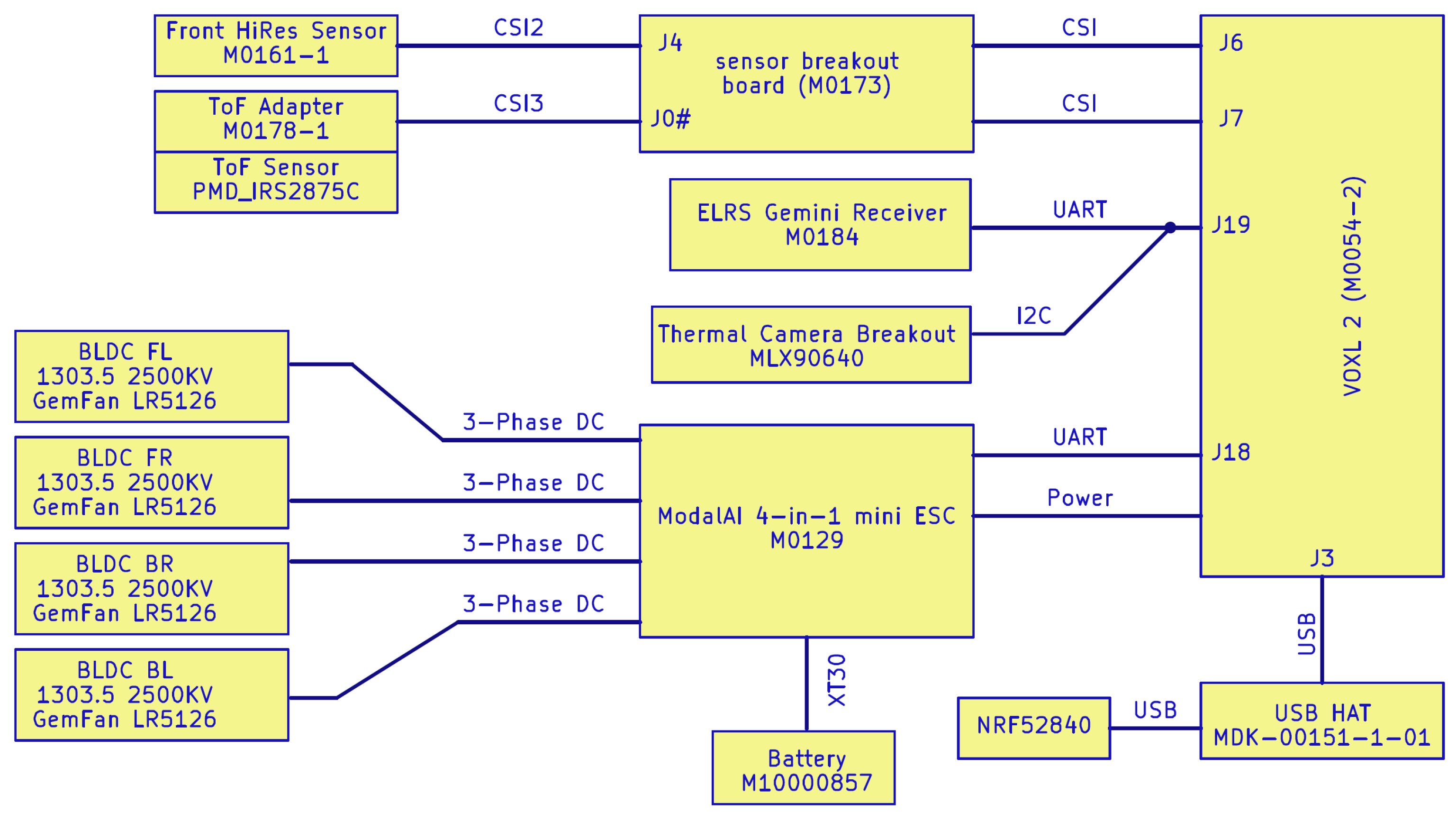
3.7. System Block Diagram
The selected flight control and companion board, perception sensors, motors, battery, electronic speed controller, and communication system are shown as a block diagram in
Figure 1.
3.8. Chassis Design
The primary objective of the chassis design was to reduce structural mass while maintaining appropriate center-of-gravity placement, stiffness, and mechanical robustness. Chassis design efforts focused on locating the motors, supporting the flight controller, ESC, and battery, and providing mounting locations for the perception sensor package, all while keeping mass and manufacturing complexity low. The design was achieved through a combination of material selection and lightweight mechanical design.
3.8.1. Chassis Material Selection
Material selection for the chassis was guided by five factors: capital investment, strength, mass, fabrication, and material cost. These criteria were weighted according to their impact on system performance, with mass receiving the highest weighting due to the sub-250 g constraint. Capital investment captured the level of specialized equipment or expertise required, while fabrication assessed the ease of manufacturing the chassis geometry. Material cost was assigned the lowest weighting, as performance and manufacturability were prioritized. The resulting feature comparison and weights are shown in
Table A10. Five candidate materials were evaluated using the weighted scoring methodology: T800 carbon fiber (3K woven face plies), PEEK, ABS, PLA, and Markforged Onyx with continuous fiber reinforcement. Relative performance scores are summarized in
Table A11 and
Table A12. Carbon fiber achieved a strong overall score (3.20) due to its excellent strength-to-weight ratio but required higher capital investment and machining effort. PEEK offered high strength and thermal resistance but was penalized by fabrication difficulty and cost. ABS and PLA scored lower overall, as their reduced stiffness and durability limited suitability for a structural airframe despite ease of fabrication.
Markforged Onyx with continuous fiber reinforcement achieved the highest overall score (3.30), offering an optimal balance of low mass, high stiffness, and manufacturability. Onyx’s nylon matrix with short carbon fibers provides improved strength and dimensional stability over conventional thermoplastics, while continuous fiber reinforcement enables near–carbon-fiber-level mechanical performance. This combination makes Markforged Onyx well suited for lightweight structural components, leading to its selection as the chassis material.
3.8.2. Chassis Mechanical Design
The chassis design started as a typical X-shaped concept. During the evolution of the design, particular attention was focused on the arm cross-section for bending stiffness, mounting features for the sensors and battery, and lightweighting features.
A key structural characteristic of the design is the T-shaped cross-section used for each motor arm. This profile significantly increased bending stiffness and torsional rigidity compared to a flat plate arm of equivalent mass, improved vibration resistance, and did not significantly impact 3D printing of the chassis. Mounting features for the sensor package and battery were integrated into the chassis. With the goal of ease of manufacturability, the main chassis was kept almost flat. The mounts were designed with tabs that could be inserted into corresponding slots in the chassis plate. It was understood that this design could introduce vibration into the cameras, but the <250g requirement prevented a more robust design. The sensor mounting plates and battery clips were bonded to the chassis using adhesive to improve structural integrity while reducing the number of fasteners and overall UAV mass.
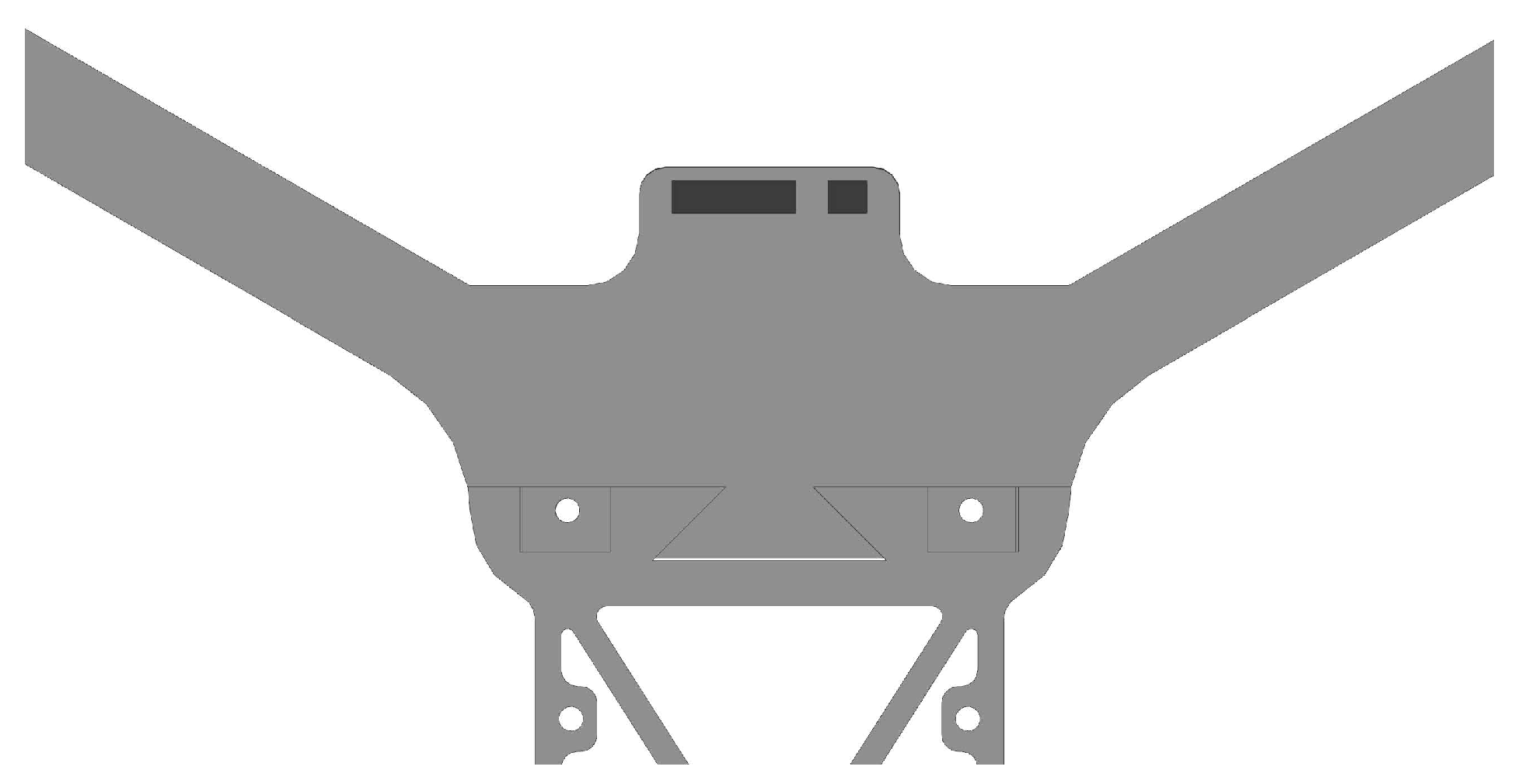
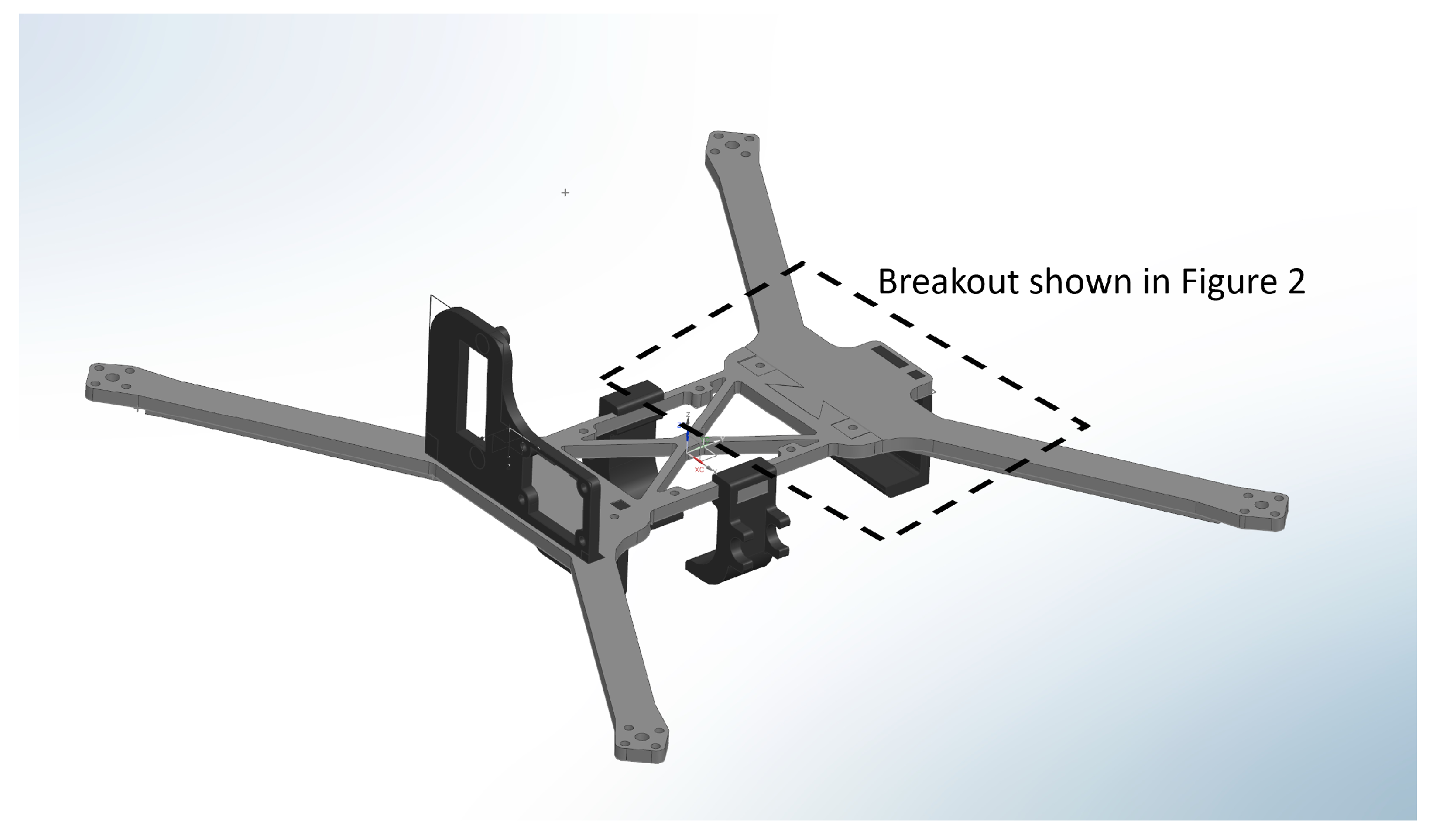
Between the motor arms and the electronics mounting points, the overall chassis was developed with a thickness of 3 mm. The chassis mid-frame incorporates an X-shaped reinforcement pattern to minimize the amount of printed material required while providing additional structural stability. The chassis is printed using Markforged Onyx reinforced with continuous carbon fiber, which provides an excellent balance of strength, stiffness, and low mass. Onyx’s nylon–carbon-fiber composite delivers high dimensional stability and impact resistance. This material choice enables a lightweight yet rigid structure that is well suited for the drone’s arms, mid-frame, and sensor mounting features. An additional chassis design feature became necessary during the manufacture of the first prototype. The length of each arm was selected from the propeller length and required clearance between the propeller tips. With the selected 5-inch propellers, the motor-to-motor length exceeded the print bed dimensions of the Markforged Onyx print bed. To overcome this limitation, the chassis was split into two components that joined with a dovetail connection, as shown in
Figure 2. This enabled the frame to be manufactured in two smaller components and then assembled into a rigid structure.
The final chassis design is shown in
Figure 3. The finalized design satisfies structural and manufacturability constraints while providing a compact and rigid platform suitable for continued development.
3.9. UAV Assembly
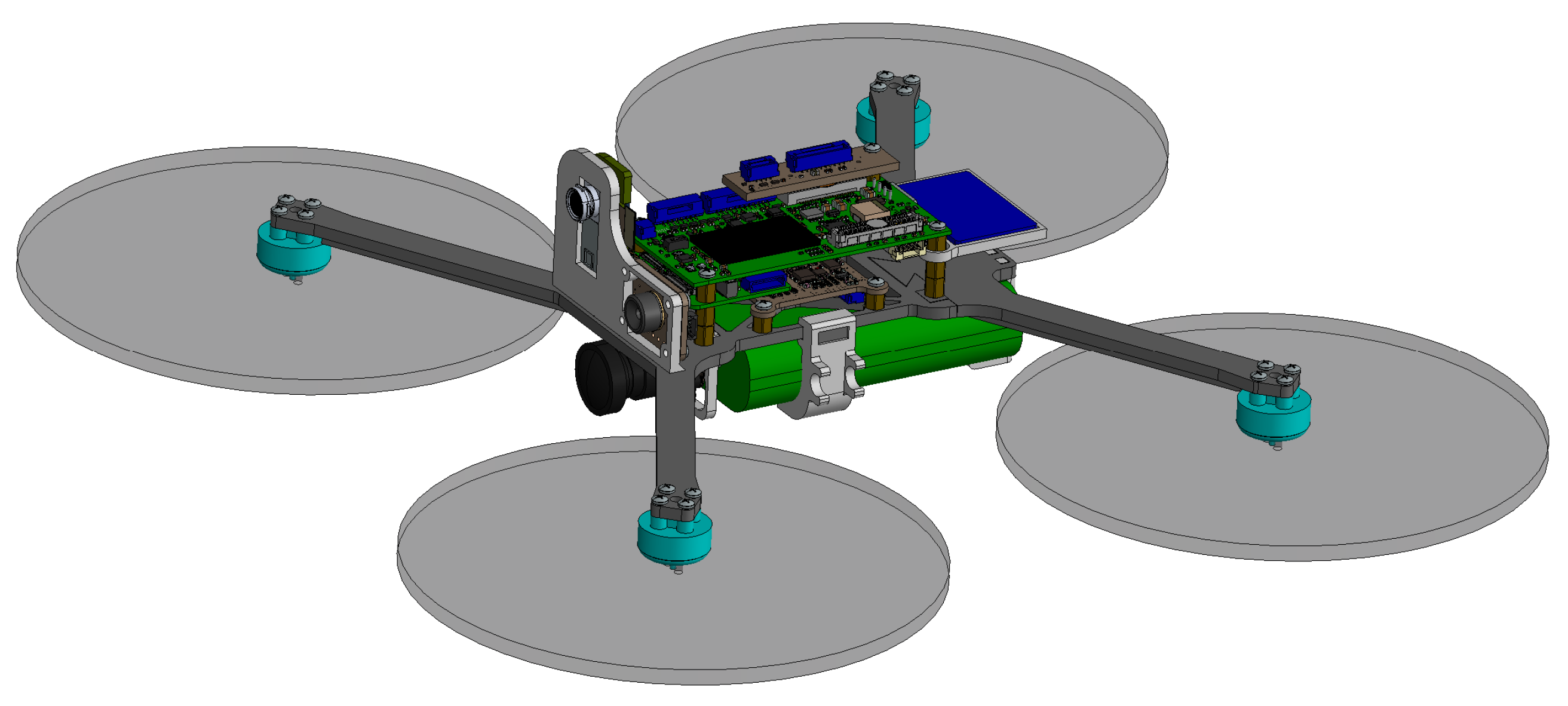
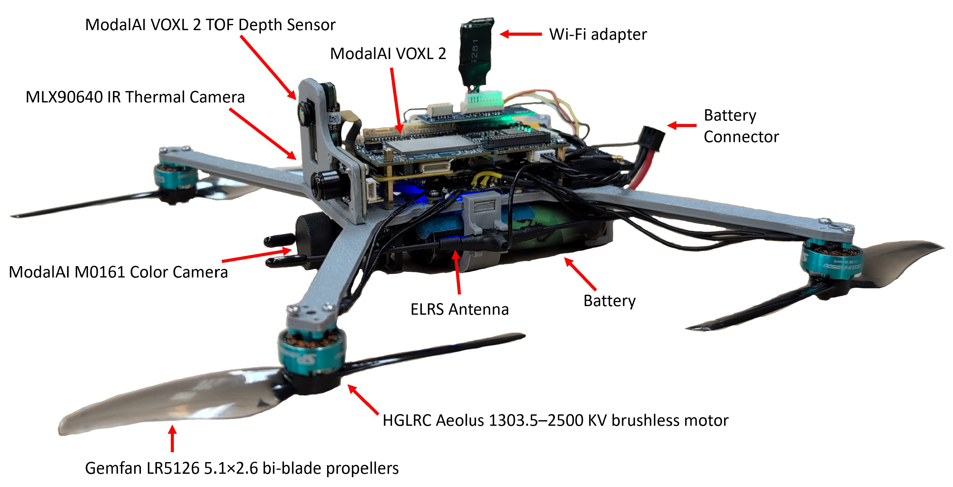
The final assembled UAV is shown as a CAD assembly in
Figure 4 and in hardware in
Figure 5. The mass achieved in the assembly was 247.34 g.
4. Validation and Testing
4.1. Blue UAS Compliance
The Blue UAS Framework emphasizes certification of critical subsystems responsible for data processing, storage, and transmission—such as flight controllers, communication modules, and perception sensors—rather than commodity components like motors or electronic speed controllers. The proposed platform follows this philosophy by prioritizing certified components while maintaining compliance with National Defense Authorization Act (NDAA) supply chain restrictions.
The system architecture was designed to align with the Blue UAS Framework 2.0 established by the Defense Innovation Unit. The ModalAI VOXL 2 flight controller was selected as the core computing and control platform and is certified as compliant with NDAA Section 848. This certification verifies adherence to Department of Defense supply chain security and operational standards. In addition, the use of associated ModalAI components, including the RGB camera and time-of-flight depth sensor, ensures that the perception stack avoids hardware sourced from prohibited entities. By selecting appropriate components, the overall UAV may be eligible for Blue UAS certification at a later date.
4.2. Perception Sensors Validation
The perception stack consists of an RGB camera, a time-of-flight (ToF) distance sensor, and a thermal camera. Each sensor was evaluated for output quality, accuracy (where applicable), and data rate. All tests were conducted over ROS by connecting the drone and a remote testing computer to a shared Wi-Fi network. Image quality was assessed through visual inspection in RViz, and output frequencies were measured using the ROS topic hz tool, with each topic sampled for two minutes to obtain an average rate.
The RGB camera was evaluated at both 4K and 720p resolutions, as summarized in
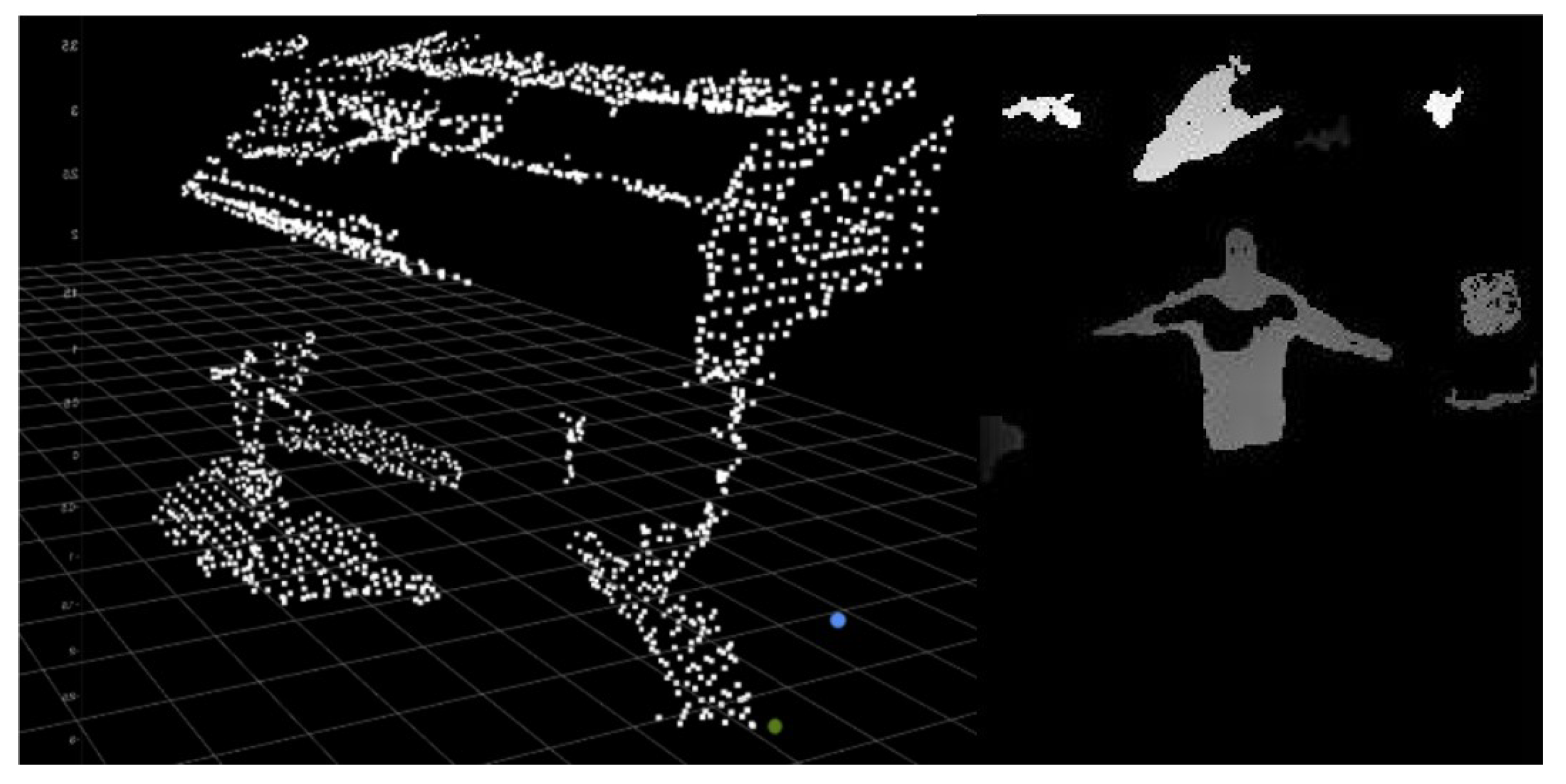
Table 4. Image quality was deemed sufficient at both resolutions for mapping and reporting tasks. The encoded 4K image stream achieved a sustained rate of 30 Hz, while the unencoded streams exhibited significantly lower bandwidth efficiency. Although the 720p encoded topic was not explicitly tested, the encoded 4K stream provided sufficient quality and frame rate for all intended use cases and was selected for system integration. The ToF distance sensor demonstrated accurate depth measurements across test distances ranging from 0.2 to 12 ft, validated using the VOXL Portal point cloud viewer. Depth data is visualized as both a depth image and a point cloud in
Figure 6. However, the point cloud topic exhibited a low and inconsistent update rate, averaging approximately 3 Hz and occasionally dropping below 1 Hz. The observed limitation is primarily attributed to the data processing and communication pipeline, including ROS 2 DDS middleware and point cloud conversion, rather than the sensor hardware itself, which is capable of higher output rates.
Due to firmware limitations, the thermal camera could not be evaluated directly on the VOXL platform and was instead tested using a Raspberry Pi 2 Model B. While this platform is significantly less capable than the VOXL and required running ROS 2 through a Docker container, it was sufficient to validate basic sensor functionality and data acquisition. However, this validation does not fully represent performance on the intended VOXL deployment platform. System-level factors such as power delivery, processing load, and thermal characteristics may influence the effective performance of the sensor when integrated into the final UAV system. In particular, onboard heat generation and power regulation differences may affect thermal measurements and data rates. Due to computational constraints, the achievable output rate was limited to approximately 2 Hz, despite the sensor’s nominal capability of higher frame rates. As a result, output rate was not used as a disqualifying metric. Full validation on the VOXL platform remains part of future work.
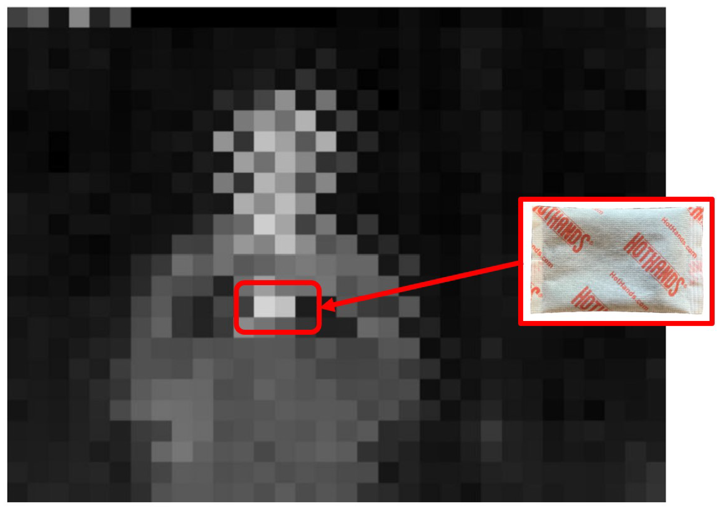
Thermal data were transmitted as a 32-bit grayscale image encoding temperature values in degrees Celsius. A lightweight decoding node was used on the remote computer to reconstruct the temperature array for validation and visualization (
Figure 7). Accuracy was assessed using a handheld infrared thermometer and was found to be within ±2 °C at distances up to 10 ft. A 2 in × 1 in hand warmer was clearly identifiable as a thermal hotspot, with measured values closely matching ground-truth readings.
4.3. Structural Validation
The structural performance of the drone frame was evaluated using a combination of finite element analysis (FEA) and physical testing. A linear static simulation was performed in SolidWorks (2022 SP5.0) on a single chassis arm modeled as a 3 mm thick printed Onyx component [
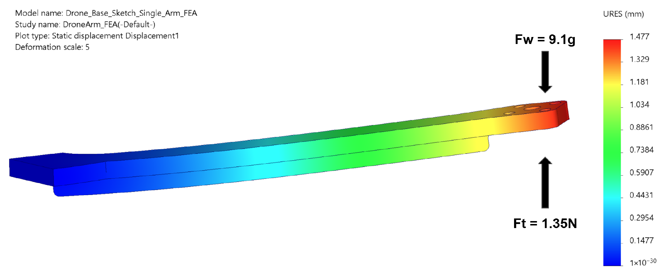
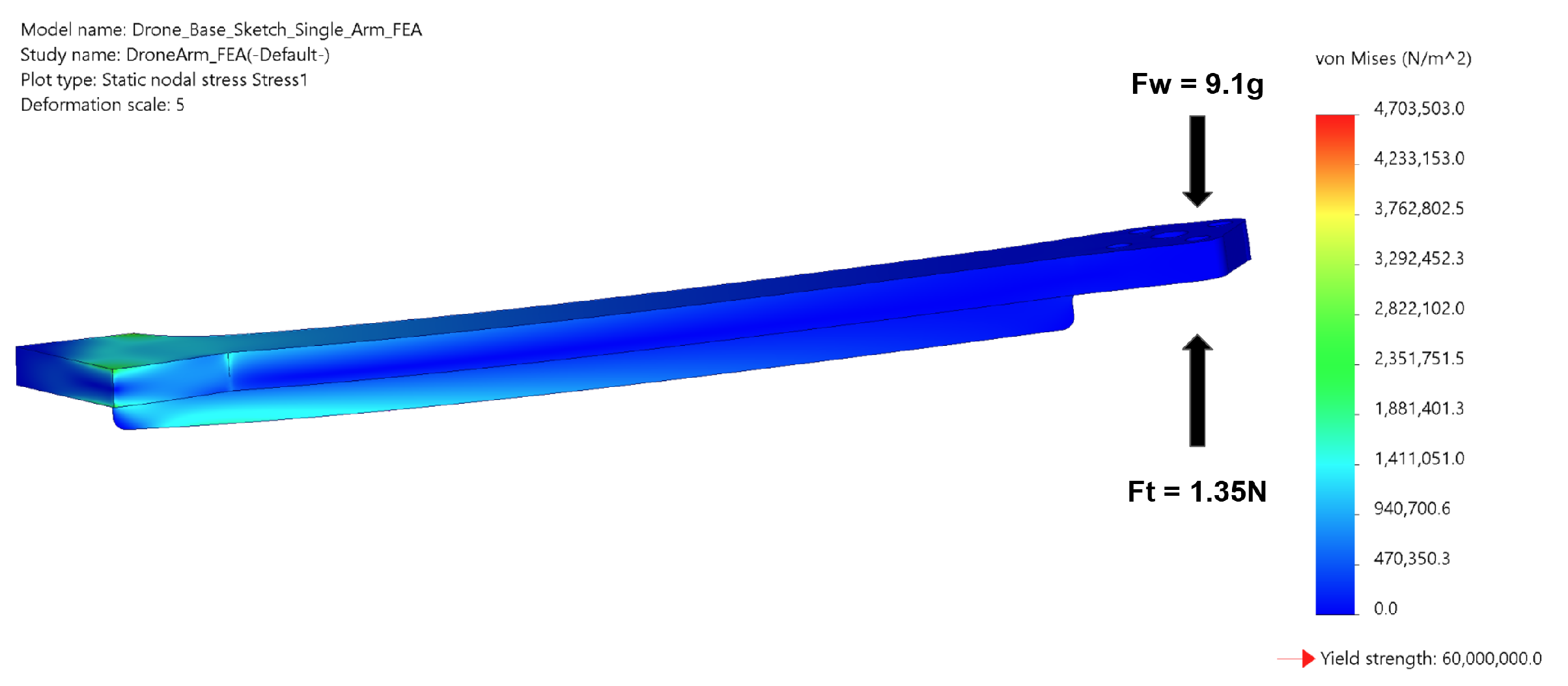
33]. The arm root was constrained as a fixed support. An upward tip load of 1.35 N from the motor thrust and a downward tip load from the motor weight were applied at the motor mounting location. This load corresponds to the maximum thrust produced by a single motor, based on a vehicle mass of 250 g, a target thrust-to-weight ratio of 2.2, and a four-motor configuration. A grid refinement study was completed, and the final study included 672,680 total nodes and 468,707 total tetrahedral elements.
FEA results indicated a maximum tip deflection of approximately 15 mm at the end of the arm (
Figure 8). The peak von Mises stress occurred at the arm-to-chassis interface and reached approximately 42 MPa (
Figure 9), remaining below the assumed material yield strength of 60 MPa for printed Onyx. This corresponds to an estimated factor of safety of approximately 1.4–1.5 under maximum static thrust conditions, indicating no expected permanent deformation during normal operation.
To validate the simulation results, a dedicated chassis was fabricated for destructive testing and assembled with representative electronics. The structure was subjected to drop tests from heights of 1 m, 2 m, and 3 m across multiple orientations, including flat, arm-first, and corner impacts. No cracks, permanent deformation, or plate loosening were observed. A single brass standoff failure occurred during the 3 m drop test, but no structural damage to the frame was detected. Additionally, vibration testing was performed by exciting the sensor mounting plates. Oscillations decayed rapidly with no visible instability, indicating a stiff and well-damped structure. Together, the FEA and physical testing confirm that the final frame design provides sufficient stiffness, strength, and impact resistance for typical flight operations, meeting all structural design requirements.
4.4. Communication Validation
The drone employs a dual communication architecture consisting of a dedicated radio link and a Wi-Fi interface. All flight control commands are transmitted over the radio link, isolating critical control functions from potential packet loss or latency caused by high-bandwidth data transmission. The Wi-Fi interface connects the drone to a ground control station (GCS), which serves as an intermediary between the user interface and the onboard system. This link carries all ROS data streams, including point clouds, images, and pose estimates.
Wi-Fi performance was evaluated by connecting both the drone and a testing computer to a shared hotspot positioned approximately 20 ft away. During testing, high-bandwidth topics—including depth point clouds, unencoded high-resolution images, and thermal imagery—were subscribed to simultaneously. Topic update rates and network latency were monitored over a 10-min interval. No significant degradation in data throughput or latency was observed compared to baseline sensor tests, and performance remained consistent with the hotspot placed at varying distances within the test range.
The radio communication system was tested at close range, at a distance of 40 ft, and through intervening walls. Across all test conditions, no noticeable delay or data loss was observed, demonstrating reliable and robust control communication.
4.5. Mission Validation
A 30-min endurance test was conducted to evaluate system performance without teleoperation over ROS, focusing on sensor stability and overall flight behavior. The test included a combination of hovering and mild maneuvering with all onboard sensors active. The fully assembled drone demonstrated stable flight and consistent sensor data transmission for approximately 28 min but did not meet the 30 min endurance requirement. The test was terminated when a noticeable discrepancy emerged between commanded and actual thrust, consistent with battery depletion.
An IMU calibration and stability test was also performed to assess flight stabilization and attitude control. The vehicle maintained stable hover within a ±0.5 m positional deviation and executed smooth attitude transitions, satisfying all performance criteria. These results confirm reliable stabilization and control behavior necessary for teleoperated missions and consistent data acquisition.
5. Discussion and Future Work
Throughout the design and fabrication process, several limitations were identified that influenced the final system configuration. Due to the constrained development timeline and the late identification of several integration challenges, these issues could not be fully addressed in the delivered prototype. This section summarizes the main limitations of the current system and outlines directions for future development.
During the system design phase, multiple sensing modalities were identified as desirable for indoor emergency response applications, including RGB imaging, thermal sensing, gas detection, audio capture, and inertial sensing. However, due to strict mass, power, and platform compatibility constraints associated with the sub-250 g UAV design, not all sensing modalities listed in the initial system requirements were integrated into the final prototype. The implemented platform focuses on RGB imaging, thermal sensing, and inertial measurement, which provide core functionality for navigation, flight stabilization, and situational awareness. Additional sensing capabilities, such as gas detection and bidirectional audio communication, remain important targets for future system iterations, where improved hardware integration or more flexible computing platforms may enable their incorporation without compromising system constraints.
A major constraint in the current design is the reliance on the VOXL computing platform. While the VOXL and VOXL Mini boards are among the few commercially available solutions capable of meeting the strict sub-250 g mass requirement, their closed ecosystem limits system modularity. Sensor compatibility is largely restricted to ModalAI-supported hardware, and available documentation is incomplete and difficult to maintain. Although an unused I2C interface is present at the hardware level, it is disabled in firmware and cannot be enabled through existing tools, preventing broader sensor integration without firmware modification.
Related firmware restrictions also affected communication and thermal sensor validation. For example, although the selected Bluetooth adapter functioned correctly on standard Linux distributions, Bluetooth over USB was disabled at the firmware level on the VOXL platform. Enabling this capability would require custom firmware modifications, which were considered out of scope for this project and could introduce long-term maintenance challenges. Similarly, full thermal sensor validation on the target VOXL platform was not completed. Due to firmware restrictions, thermal testing was performed on a Raspberry Pi platform, which differs from the deployed UAV computing platform in computational capability, power delivery, and thermal behavior. Therefore, while basic thermal sensor functionality was verified, complete system-level performance on the final UAV platform remains to be validated.
Another limitation is the current data processing and communication pipeline. Although the sensing hardware is capable of higher frame rates, the effective point cloud update rate was reduced by the current software implementation, including ROS 2 DDS middleware, message serialization, and point cloud generation. This limitation is therefore not attributed to the sensing hardware itself but rather to the data handling and communication pipeline. Future work should investigate more efficient message formats, image transport methods, and optimized DDS configurations. In particular, switching from the default Fast DDS implementation to Cyclone DDS may improve throughput and latency.
Future communication architectures may also benefit from revisiting Bluetooth-based data transfer. While ROS communication over Wi-Fi functions reliably, Bluetooth communication would require a bridging layer capable of selectively serializing and transmitting ROS messages. Although this approach increases system complexity, modern Bluetooth hardware can achieve data rates comparable to 2.4 GHz Wi-Fi while providing more controlled and efficient transmission of selected data streams. Alternative middleware solutions, such as Zenoh, may also provide promising performance improvements for large data streams and distributed robotic systems, although they are not yet officially supported within the core ROS ecosystem.
The current prototype was also not fully validated in real-world firefighting environments. While subsystem-level testing was performed for sensing, communication, and structural performance, the UAV has not yet been deployed in operational indoor firefighting or post-fire inspection scenarios. As such, the current results should be interpreted as a proof-of-concept demonstration rather than a fully validated field-ready system. Future work will focus on task-level validation in realistic environments to evaluate system performance under practical deployment conditions.
An additional direction for future development involves advanced visualization and digital twin integration. During early development stages, preliminary experiments were conducted using Unreal Engine in combination with ModalAI visualization tools to explore immersive environment reconstruction and operator interfaces. However, this functionality was not fully integrated with the final UAV platform presented in this work. Future research will focus on connecting ROS 2 data streams from the UAV to an Unreal Engine–based visualization environment to enable real-time three-dimensional scene reconstruction, thermal hotspot visualization, and improved situational awareness for incident commanders. Such an interface could support enhanced decision-making during emergency response operations by providing a spatial representation of UAV sensor data within a digital twin of the operating environment.
6. Conclusions
This paper presented the design and preliminary validation of a sub-250 g UAV platform with a total system mass of 247.34 g and a total system cost of $2969, intended as a proof-of-concept for post-fire indoor inspection and situational assessment. The redesigned airframe achieved the required strength, rigidity, and manufacturability, with finite element analysis and physical drop testing confirming structural integrity under thrust loading and impacts up to 3 m. Subsystem-level testing demonstrated reliable performance of the RGB, ToF, thermal, radio, and Wi-Fi components, highlighting the feasibility of integrating multimodal sensing within strict mass and power constraints. These results support the viability of a constraint-driven UAV design tailored for first-responder deployment in confined and hazardous environments. While certain limitations remain, including constraints in the current software pipeline and platform-level integration, the proposed system establishes a strong foundation for future development. The platform enables continued work toward improved sensing performance, expanded system capabilities, and integration with advanced visualization and digital twin frameworks for enhanced situational awareness in emergency response operations.
Author Contributions
Conceptualization, R.S. and J.A.M.; methodology, R.S., C.O., A.R.M., A.K.M.Z., S.S. and J.A.M.; software, C.O. and A.R.M.; validation, C.O., A.R.M., A.K.M.Z. and S.S.; formal analysis, C.O., A.R.M. and S.S.; investigation, C.O., A.R.M., A.K.M.Z. and S.S.; resources, R.S. and J.A.M.; data curation, C.O. and A.R.M.; writing—original draft preparation, R.S.; writing—review and editing, R.S., Y.K.L. and J.A.M.; visualization, C.O. and A.R.M.; supervision, R.S. and J.A.M.; project administration, R.S. and J.A.M.; funding acquisition, R.S. and J.A.M. All authors have read and agreed to the published version of the manuscript.
Funding
This research was funded by Mutually Assured Development, LLC. Blue Devil Ventures serves as the managing studio entity supporting Mutually Assured Development, LLC.
Data Availability Statement
The original contributions presented in this study are included in the article. Further inquiries can be directed to the corresponding author.
Acknowledgments
The authors would like to thank Pedro Guillen, Margarita Hernandez, and Southfield Fire Department for their guidance and technical insights provided during the development of this work.
Conflicts of Interest
Roya Salehzadeh has been involved as a technical advisor to Mutually Assured Development, LLC. Yeen K. Lee has been involved as a part-time employee of Mutually Assured Development, LLC. James A. Mynderse has been involved as a technical advisor to Mutually Assured Development, LLC.
Abbreviations
The following abbreviations are used in this manuscript:
| CAD | Computer-Aided Design |
| CG | Center of Gravity |
| ESC | Electronic Speed Controller |
| FEA | Finite Element Analysis |
| GCS | Ground Control Station |
| IMU | Inertial Measurement Unit |
| I2C | Inter-Integrated Circuit |
| PX4 | Pixhawk Autopilot Firmware |
| RGB | Red, Green, Blue (color imaging) |
| ROS | Robot Operating System |
| SLAM | Simultaneous Localization and Mapping |
| ToF | Time-of-Flight |
| UAV | Unmanned Aerial Vehicle |
| USB | Universal Serial Bus |
| Wi-Fi | Wireless Fidelity |
Appendix A. Detailed Component Selection Tables
The feature comparison tables present the pairwise comparison matrices used to derive the criterion weights for the component selection process. Each table compares the relative importance of evaluation criteria by indicating, for each pair, which criterion is preferred. The letter in each cell denotes the more important criterion in that comparison. The “Total” column represents the number of times each criterion is preferred across all comparisons, and the “Weight” column is obtained by normalizing these totals to reflect the relative importance of each criterion. For example, in
Table A1, the first row indicates that “Mass (A)” is preferred over all other criteria, resulting in the highest total score and corresponding weight.
Table A1.
Feature Comparison Scoring.
Table A1.
Feature Comparison Scoring.
| Feature | A | B | C | D | E | F | G | Total | Weight |
|---|
| Mass (A) | – | A | A | A | A | A | A | 6 | 27% |
| Affordability (B) | | – | C | B | E | F | B | 2 | 9% |
| Durability (C) | | | – | D | CE | F | G | 2 | 9% |
| Usability (End User) (D) | | | | – | E | F | G | 1 | 5% |
| Fabricability (E) | | | | | – | F | G | 3 | 14% |
| Maintainability (F) | | | | | | – | F | 5 | 23% |
| Assemblability (G) | | | | | | | – | 3 | 14% |
Table A2.
Averaged Weighted Feature Scores for FC Selection.
Table A2.
Averaged Weighted Feature Scores for FC Selection.
| Criterion | Wt. | VOXL 2 | VOXL 2 Mini |
|---|
| Rating | Score | Rating | Score |
|---|
| Mass | 27% | 3.75 | 1.02 | 5.00 | 1.36 |
| Affordability | 9% | 2.25 | 0.20 | 1.50 | 0.14 |
| Durability | 9% | 3.00 | 0.27 | 3.00 | 0.27 |
| Usability (End User) | 5% | 4.00 | 0.18 | 1.75 | 0.08 |
| Fabricability | 14% | 3.75 | 0.51 | 2.75 | 0.38 |
| Maintainability | 23% | 3.75 | 0.85 | 2.75 | 0.63 |
| Assemblability | 14% | 3.75 | 0.51 | 3.25 | 0.44 |
| Total | | | 3.56 | | 3.30 |
Table A3.
Averaged Weighted Feature Scores for Thermal Camera Selection.
Table A3.
Averaged Weighted Feature Scores for Thermal Camera Selection.
| Criterion | Wt. | FLIR Lepton | MLX90640 |
|---|
| Rating | Score | Rating | Score |
|---|
| Mass | 27% | 2.25 | 0.61 | 4.00 | 1.09 |
| Affordability | 9% | 2.00 | 0.18 | 4.00 | 0.36 |
| Durability | 9% | 3.00 | 0.27 | 2.75 | 0.25 |
| Usability (End User) | 5% | 2.25 | 0.10 | 3.25 | 0.15 |
| Fabricability | 14% | 2.50 | 0.34 | 4.00 | 0.55 |
| Maintainability | 23% | 3.00 | 0.68 | 3.00 | 0.68 |
| Assemblability | 14% | 2.00 | 0.27 | 3.00 | 0.41 |
| Total | | | 2.47 | | 3.49 |
Table A4.
Feature Comparison Table for Motor–Propeller Set Selection.
Table A4.
Feature Comparison Table for Motor–Propeller Set Selection.
| Feature | A | B | C | D | Total | Weight |
|---|
| Mass (A) | – | A | C | A | 2 | 29% |
| Cost (B) | | – | C | D | 0 | 0% |
| Current Draw (C) | | | – | CD | 3 | 43% |
| Thrust (D) | | | | – | 2 | 29% |
Table A5.
Feature Comparison Table for Battery Selection.
Table A5.
Feature Comparison Table for Battery Selection.
| Feature | A | B | C | D | E | Total | Weight |
|---|
| Mass (A) | – | A | A | A | A | 5 | 50% |
| Throughput (B) | | – | B | B | A | 2 | 20% |
| Cost (C) | | | – | D | E | 0 | 0% |
| Operability (D) | | | | – | E | 1 | 10% |
| Availability (E) | | | | | – | 2 | 20% |
Table A6.
Feature Comparison Table Used for ESC Selection.
Table A6.
Feature Comparison Table Used for ESC Selection.
| Feature | A | B | C | Total | Weight |
|---|
| Mass (A) | – | A | C | 1 | 33% |
| Cost (B) | | – | C | 0 | 0% |
| Current Draw (C) | | | – | 2 | 67% |
Table A7.
Weighted Scoring Comparison for Top Three ESC Options.
Table A7.
Weighted Scoring Comparison for Top Three ESC Options.
| Criterion | Wt. | ModalAI M0129 | ModalAI M0138 | Holybro Tekko32 |
|---|
| Rating | Score | Rating | Score | Rating | Score |
|---|
| Mass | 33% | 5 | 1.67 | 1 | 0.33 | 2 | 0.67 |
| Cost | 0% | 1 | 0.00 | 1 | 0.00 | 5 | 0.00 |
| Current Draw | 67% | 3 | 2.00 | 5 | 3.33 | 4 | 2.67 |
| Total | | | 3.67 | | 3.67 | | 3.33 |
Table A8.
Feature Comparison Table for Communication System Selection.
Table A8.
Feature Comparison Table for Communication System Selection.
| Feature | A | B | C | D | E | F | Total | Weight |
|---|
| Current Draw (A) | – | B | A | A | A | A | 4 | 27% |
| Mass (B) | | – | B | B | B | B | 5 | 33% |
| Range (C) | | | – | C | E | F | 1 | 6.7% |
| Cost (D) | | | | – | E | D | 1 | 6.7% |
| Integration (E) | | | | | – | E | 3 | 20% |
| Assembly (F) | | | | | | – | 1 | 6.7% |
Table A9.
Weighted Scoring Comparison for Data Transfer Module Selection.
Table A9.
Weighted Scoring Comparison for Data Transfer Module Selection.
| Criterion | Wt. | MicroHard | NRF52840-DONGLE |
|---|
| Rating | Score | Rating | Score |
|---|
| Current Draw | 27% | 2 | 0.53 | 4 | 1.07 |
| Mass | 33% | 1 | 0.33 | 4 | 1.33 |
| Range | 6.7% | 5 | 0.33 | 3 | 0.20 |
| Cost | 6.7% | 1 | 0.07 | 4 | 0.27 |
| Integration | 20% | 2 | 0.40 | 4 | 0.80 |
| Assembly | 6.7% | 2 | 0.13 | 4 | 0.27 |
| Total | | | 1.80 | | 3.93 |
Table A10.
Comparison table used for material selection.
Table A10.
Comparison table used for material selection.
| Feature | A | B | C | D | E | Total | Weight |
|---|
| Capital Investment (A) | – | B | C | D | A | 1 | 10% |
| Strength (B) | | – | C | D | B | 2 | 20% |
| Mass (C) | | | – | C | C | 4 | 40% |
| Fabrication (D) | | | | – | D | 3 | 30% |
| Material Cost (E) | | | | | – | 0 | 0% |
Table A11.
Relative performance of carbon fiber, PEEK, and ABS based on the weighted scale.
Table A11.
Relative performance of carbon fiber, PEEK, and ABS based on the weighted scale.
| Selection Criteria | Wt. | Carbon Fiber | PEEK | ABS |
|---|
| Rating | Score | Rating | Score | Rating | Score |
|---|
| Capital Investment | 10% | 3 | 0.30 | 2 | 0.20 | 4 | 0.40 |
| Strength | 20% | 4 | 0.80 | 3 | 0.60 | 1 | 0.20 |
| Mass | 40% | 3 | 1.20 | 3 | 1.20 | 2 | 0.80 |
| Fabrication | 30% | 3 | 0.90 | 2 | 0.60 | 4 | 1.20 |
| Material Cost | 0% | 2 | 0.00 | 1 | 0.00 | 5 | 0.00 |
| Total Score | | 3.20 | 2.60 | 2.60 |
Table A12.
Relative performance of PLA and Markforged Onyx on the weighted scale.
Table A12.
Relative performance of PLA and Markforged Onyx on the weighted scale.
| Selection Criteria | Wt. | PLA | Markforged Onyx |
|---|
| Rating | Score | Rating | Score |
|---|
| Capital Investment | 10% | 4 | 0.40 | 4 | 0.40 |
| Strength | 20% | 1 | 0.20 | 2 | 0.40 |
| Mass | 40% | 2 | 0.80 | 4 | 1.60 |
| Fabrication | 30% | 4 | 1.20 | 3 | 0.90 |
| Material Cost | 0% | 5 | 0.00 | 1 | 0.00 |
| Total Score | | 2.60 | 3.30 |
References
- Bralewska, K.; Rogula-Kozłowska, W.; Białas, J.; Dmochowska, A. Assessment of firefighters’ health exposure to indoor air pollutants inside fire station. Indoor Built Environ. 2025, 34, 1829–1843. [Google Scholar] [CrossRef]
- Alharbi, B.H.; Pasha, M.J.; Al-Shamsi, M.A.S. Firefighter exposures to organic and inorganic gas emissions in emergency residential and industrial fires. Sci. Total Environ. 2021, 770, 145332. [Google Scholar] [CrossRef] [PubMed]
- Yang, J.; Ding, T.; Deng, Q.; Li, Z.; Wang, Y.; Wu, J.; Shi, M. A Multi-UAV Indoor Air Real-Time Detection and Gas Source Localization Method Based on Improved Teaching–Learning-Based Optimization. Atmos. Environ. 2024, 318, 120200. [Google Scholar] [CrossRef]
- Unlu, H.U.; Chaikalis, D.; Tsoukalas, A.; Tzes, A. UAV Indoor Exploration for Fire-Target Detection and Extinguishing. J. Intell. Robot. Syst. Theory Appl. 2023, 108, 54. [Google Scholar] [CrossRef]
- Khan, A.; Gupta, S.; Gupta, S.K. Emerging UAV technology for disaster detection, mitigation, response, and preparedness. J. Field Robot. 2022, 39, 905–955. [Google Scholar] [CrossRef]
- Zhuang, L.; Zhong, X.; Xu, L.; Tian, C.; Yu, W. Visual SLAM for Unmanned Aerial Vehicles: Localization and Perception. Sensors 2024, 24, 2980. [Google Scholar] [CrossRef] [PubMed]
- Karam, S.; Nex, F.; Chidura, B.T.; Kerle, N. Microdrone-Based Indoor Mapping with Graph SLAM. Drones 2022, 6, 352. [Google Scholar] [CrossRef]
- Daud, S.M.S.M.; Yusof, M.Y.P.M.; Heo, C.C.; Khoo, L.S.; Singh, M.K.C.; Mahmood, M.S.; Nawawi, H. Applications of drone in disaster management: A scoping review. Sci. Justice 2022, 62, 30–42. [Google Scholar] [CrossRef] [PubMed]
- Truong, N.N.; Tran, L.A.; Le, M.H.; Nguyen, T.D.; Do, T.D.; Trinh, H.H. Efficient Infrared and Thermal Imaging Fusion Approach for Real-time Human Detection in Heavy Smoke Scenarios. In 2023 International Conference on System Science and Engineering (ICSSE); IEEE: Piscataway, NJ, USA, 2023. [Google Scholar] [CrossRef]
- Wankmüller, C.; Kunovjanek, M.; Mayrgündter, S. Drones in emergency response – evidence from cross-border, multi-disciplinary usability tests. Int. J. Disaster Risk Reduct. 2021, 65, 102567. [Google Scholar] [CrossRef]
- Epic Games. Unreal Engine Download. 2026. Available online: https://www.unrealengine.com/download (accessed on 16 April 2026).
- ModalAI. Starling 2 Documentation. 2026. Available online: https://docs.modalai.com/starling-2/ (accessed on 15 February 2026).
- Raspberry Pi. Raspberry Pi Compute Module 4. 2026. Available online: https://www.raspberrypi.com/products/compute-module-4/?variant=raspberry-pi-cm4001000 (accessed on 15 February 2026).
- ModalAI. VOXL2 Datasheets. 2025. Available online: https://docs.modalai.com/voxl2-datasheets/ (accessed on 1 October 2025).
- ModalAI. VOXL2 Mini Datasheets. 2025. Available online: https://docs.modalai.com/voxl2-mini-datasheets/ (accessed on 1 October 2025).
- ModalAI. Image Sensor 4K High-Resolution, Low-Light Sensor for VOXL (Starvis IMX412, MSU-M0161). 2026. Available online: https://www.modalai.com/collections/blue-uas-framework-components/products/msu-m0161 (accessed on 15 February 2026).
- ModalAI. Image Sensor 1520p FPV Low-Light for VOXL 2 (Starvis 2 IMX664, MSU-M0186). 2026. Available online: https://www.modalai.com/collections/blue-uas-framework-components/products/msu-m0186 (accessed on 15 February 2026).
- ModalAI. VOXL 2 Time of Flight (ToF) Depth Sensor. 2025. Available online: https://www.modalai.com/products/m0178 (accessed on 20 October 2025).
- STMicroelectronics. VL53L5CX Time-of-Flight Ranging Sensor Datasheet. 2025. Available online: https://www.st.com/resource/en/datasheet/vl53l5cx.pdf (accessed on 15 February 2026).
- FLIR Systems Inc. FLIR Lepton 2.5 Thermal Imaging Module Datasheet. 2025. Available online: https://cdn.sparkfun.com/assets/6/0/1/5/7/DS-16465-FLiR_Lepton_8760_-_Thermal_Imaging_Module.pdf (accessed on 1 October 2025).
- Adafruit Industries. MLX90640 IR Thermal Camera Breakout—55 Degree. 2026. Available online: https://www.adafruit.com/product/4407 (accessed on 15 February 2026).
- Hammer, T. Free fall drag estimation of small-scale multirotor unmanned aircraft systems using computational fluid dynamics and wind tunnel experiments. CEAS Aeronaut. J. 2024, 15, 269–282. [Google Scholar] [CrossRef]
- eCalc. xcopterCalc—Multicopter Calculator. 2025. Available online: https://www.ecalc.ch/xcoptercalc.php (accessed on 23 October 2025).
- Pyrodrone. HGLRC Aeolus 1303.5 2500 KV Micro Motor. 2025. Available online: https://pyrodrone.com/products/hglrc-aeolus-1303-5-2500kv-micro-motor (accessed on 23 October 2025).
- Markforged. Composite Materials Datasheet. 2026. Available online: https://s3.amazonaws.com/mf.product.doc.images/Datasheets/Material+Datasheets/CompositesMaterialDatasheet.pdf (accessed on 15 February 2026).
- Theys, B.; Dimitriadis, G.; Hendrick, P.; De Schutter, J. Influence of propeller configuration on propulsion system efficiency of multi-rotor Unmanned Aerial Vehicles. In 2016 International Conference on Unmanned Aircraft Systems (ICUAS); IEEE: Piscataway, NJ, USA, 2016; pp. 195–201. [Google Scholar] [CrossRef]
- Zabunov, S.; Mardirossian, G. SCALES FOR MEASURING UAV MICRO-MOTOR STATIC THRUST. Aerosp. Res. Bulg. 2018, 30, 96–102. [Google Scholar] [CrossRef]
- Sharma, P.; Atkins, E. Experimental Investigation of Tractor and Pusher Hexacopter Performance. J. Aircr. 2019, 56, 1920–1934. [Google Scholar] [CrossRef]
- BetaFPV. Building Sub-250 6S 5-Inch FPV Drone: BetaFPV X-Knight 5. 2025. Available online: https://oscarliang.com/betafpv-x-knight-toothpick (accessed on 23 October 2025).
- Gemfan. LR5126 2-Blade T-Mount Propeller Specifications. 2025. Available online: https://www.getfpv.com/gemfan-lr5126-2-blade-t-mount-propeller-set-of-4-1-5mm.html (accessed on 23 October 2025).
- Microhard Systems. pMDDL Series Long-Range Data Link. 2025. Available online: https://www.modalai.com/collections/voxl-add-ons/products/voxl-microhard-modem-usb-hub (accessed on 23 October 2025).
- Nordic Semiconductor. nRF52840 Dongle Product Specification. 2025. Available online: https://www.nordicsemi.com/Products/Development-hardware/nrf52840-dongle (accessed on 23 October 2025).
- Dassault Systèmes. SOLIDWORKS Official Website. 2026. Available online: https://www.solidworks.com/ (accessed on 16 April 2026).
| Disclaimer/Publisher’s Note: The statements, opinions and data contained in all publications are solely those of the individual author(s) and contributor(s) and not of MDPI and/or the editor(s). MDPI and/or the editor(s) disclaim responsibility for any injury to people or property resulting from any ideas, methods, instructions or products referred to in the content. |




 ,
,