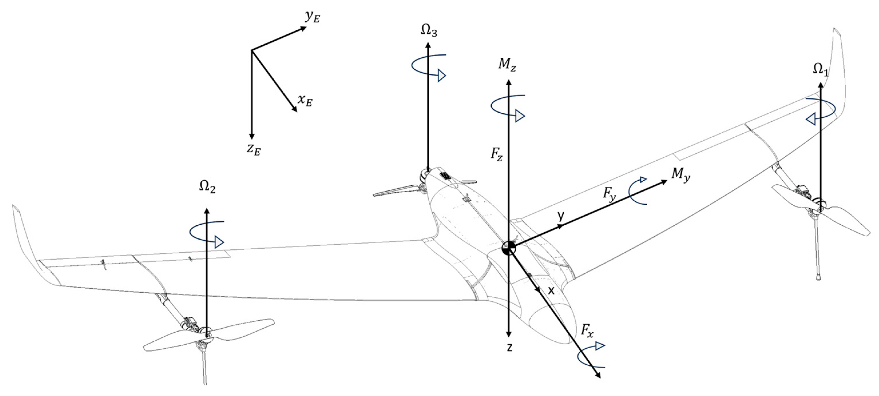
1. Introduction
Unmanned aerial vehicles (UAVs) are now widely used in surveillance, environmental monitoring, mapping, infrastructure inspection, and logistics because they can provide flexible deployment, reduced operating costs, and mission-specific aerodynamic efficiency [
1,
2,
3]. Within this broader field, hybrid fixed-wing/VTOL (Vertical Take-Off and Landing) platforms have attracted particular attention because they combine vertical take-off and landing capability with the endurance and cruise efficiency of conventional fixed-wing aircraft [
4,
5,
6]. This architectural combination is especially attractive for medium-endurance missions requiring operation from constrained areas while preserving forward-flight efficiency.
From a design perspective, however, hybrid VTOL UAVs are more demanding than conventional fixed-wing aircraft because the airframe must accommodate multiple propulsion units, external structural supports, and mission-dependent transitions between distinct flight regimes [
4,
5,
6,
7,
8]. As a result, the structural design process cannot rely only on nominal cruise loading. Preliminary sizing must also account for maneuver and atmospheric gust loads, which are commonly represented through V–n diagrams and certification-oriented envelope methods [
7,
8,
9,
10]. For relatively lightweight UAVs, these load cases are particularly important because low inertia, reduced wing loading, and compact airframes can increase sensitivity to turbulence, gusts, and operational disturbances [
9,
10].
For this reason, aerodynamic characterization is a necessary step in early wing design. High-fidelity CFD (Computational Fluid Dynamics) analysis is widely used in recent UAV studies to estimate global aerodynamic coefficients, distributed pressure fields, and configuration-level interference effects in integrated airframes [
11,
12,
13,
14]. At the same time, local aerodynamic refinement remains important at the wing level, especially when wingtip devices are used to control induced drag and spanwise loading. Recent studies continue to show that winglets and related nonplanar tip concepts can improve aerodynamic efficiency, modify tip-vortex development, and influence stability and loading distribution in small aircraft and UAV applications [
15,
16]. Accordingly, both the full-aircraft aerodynamic response and the sectional pressure distribution of the wing must be considered when the objective is not only aerodynamic assessment, but also structurally informed material selection.
This directly motivates the use of composite materials. Fiber-reinforced polymer laminates remain highly attractive for aerospace structures because of their high specific stiffness and strength, geometric adaptability, and suitability for tailored structural layouts [
17,
18,
19,
20,
21,
22]. However, the selection of a laminate system for a UAV wing should not be based solely on weight reduction. It must reflect the actual load environment, the dominant structural demand, the likely presence of local discontinuities, and the expected balance between stiffness, strength, and damage tolerance [
18,
19,
20,
21,
22]. In this context, standardized tensile, open-hole tensile, and flexural tests provide a practical basis for screening laminate candidates intended for primary wing structures [
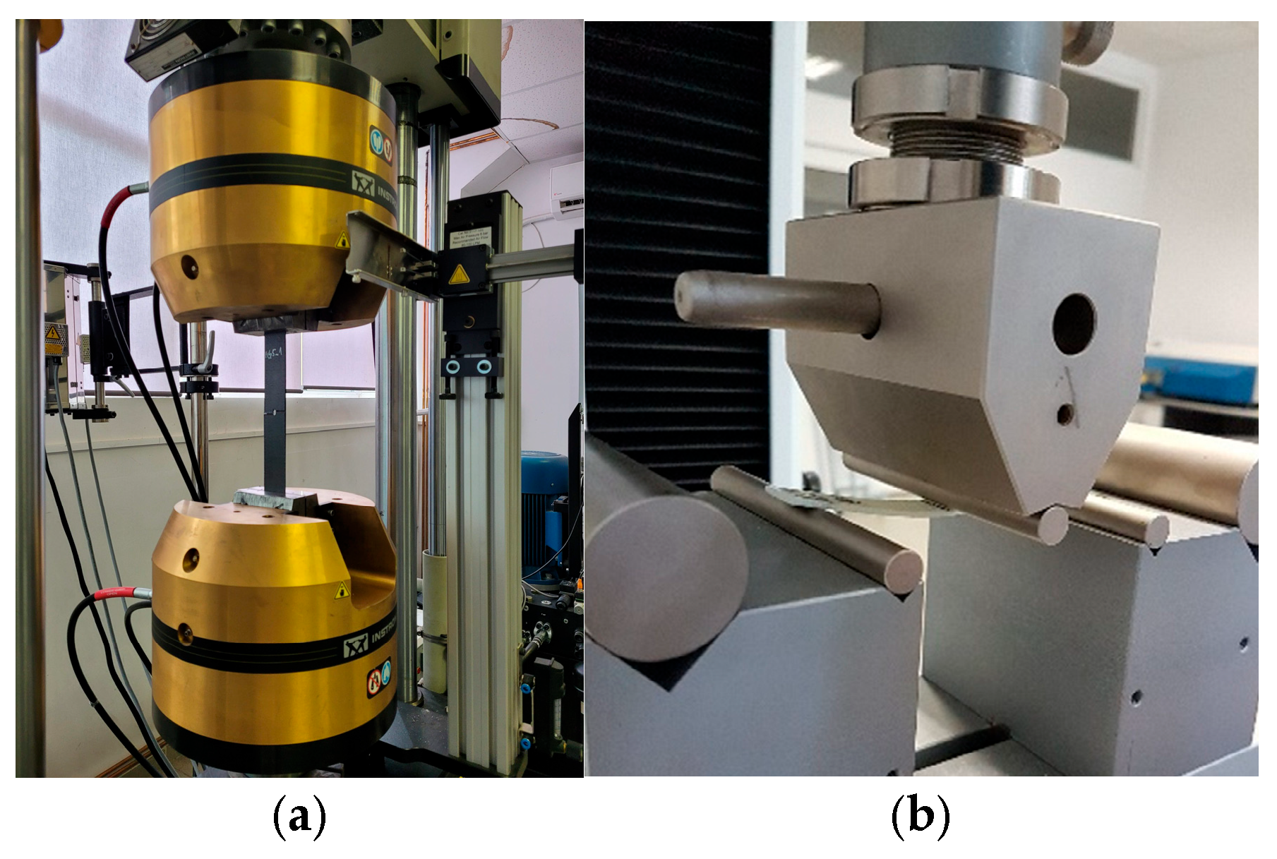
23,
24,
25]. Recent work on open-hole behavior, progressive damage, and composite failure modeling also confirms that fiber architecture and stacking sequence strongly influence structural performance, particularly in aerospace-like loading conditions [
26,
27,
28,
29,
30].
In parallel, recent research on composite wing design and aeroelastic tailoring has shown that material layout, laminate architecture, and structural optimization can significantly influence the performance of UAV and aircraft wing structures [
31,
32,
33,
34,
35]. Nevertheless, aerodynamic loading, maneuver/gust-envelope definition, and laminate selection are still often treated as separate tasks in preliminary UAV development. A practical need therefore remains for a methodology that uses certification-based load envelopes to define the structural demand, CFD to characterize the aerodynamic state and distributed pressure loading of the aircraft and wing, and experimental testing to identify the laminate system most appropriate for the dominant load modes. On this basis, the present work proposes a flight-envelope-based aerodynamic load assessment and composite material selection workflow for a hybrid tri-rotor VTOL fixed-wing UAV, with emphasis on the preliminary matching between load environment, aerodynamic response, and experimentally measured laminate capability.
3. Results
3.1. Full-Aircraft Aerodynamic Characteristics at the Nominal Cruise Condition
The full-aircraft cruise simulation established a preliminary CFD-based aerodynamic loading baseline for the hybrid VTOL UAV under the nominal operating condition. In this subsection, the aerodynamic results are presented in terms of global coefficients, distributed pressure patterns and the configuration-level interference effects generated by the fuselage and the externally mounted VTOL system.
The nominal cruise simulation yielded the global aerodynamic coefficients as summarized in
Table 3. At the prescribed operating condition, the full-aircraft configuration generated a lift coefficient of
, a drag coefficient of
, and a pitching-moment coefficient of
, corresponding to an aerodynamic efficiency of
. These values define the preliminary aerodynamic baseline used in the subsequent interpretation of the distributed pressure field and configuration-level load mechanisms.
To clarify the origin of the global aerodynamic response, the forces contributions of the main external components were evaluated separately. As expected, the wing provided the dominant lift contribution, whereas the fuselage and externally mounted VTOL system increased the total drag and influenced the global pitching moment through local interference effects and geometric offset from the reference moment point. The results are presented in
Table 4.
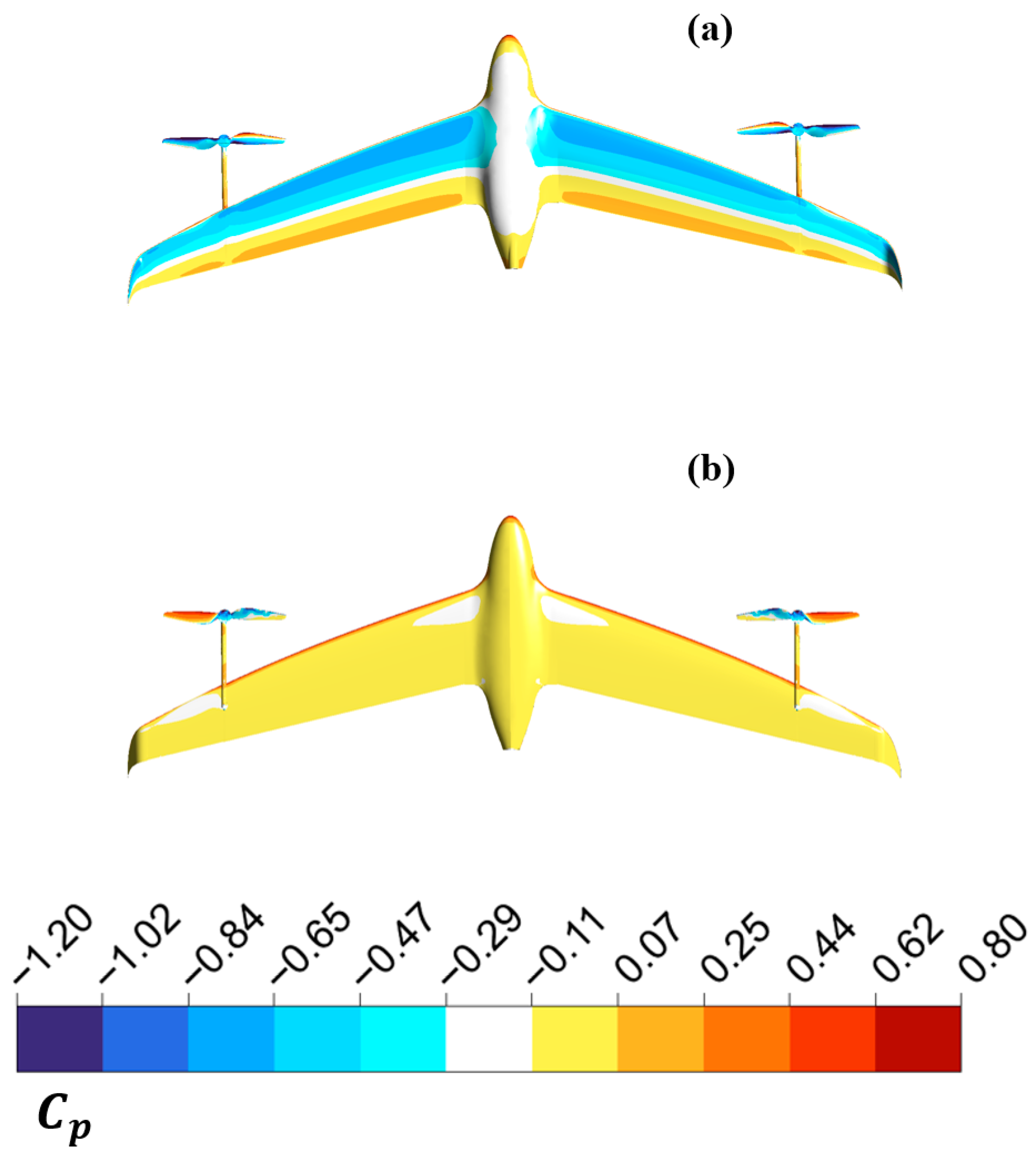
The global coefficient values are consistent with the surface pressure-coefficient distributions shown in
Figure 10. On the upper side of the aircraft, an extended region of negative
is observed over the wing, indicating suction-driven lift generation, while the lower surface exhibits milder pressure levels closer to freestream conditions and locally positive pressure regions near stagnation zones. The strongest pressure gradients occur near the wing leading edge and in the wing-body blending region, where three-dimensional flow effects become significant.
The lower-surface distribution confirms that the pressure loading is not uniform along the span, with local modifications introduced by the fuselage junction and by the VTOL support structures mounted beneath the wing.
In contrast to an isolated wing solution, the full-aircraft CFD reveals clear configuration-level interference effects. The fuselage modifies the inboard pressure field through local acceleration and flow redistribution in the wing-root region, while the externally mounted VTOL supports introduce additional localized disturbances beneath the wing. These interactions help explain the difference between the isolated-wing aerodynamic trends and the integrated full-aircraft response.
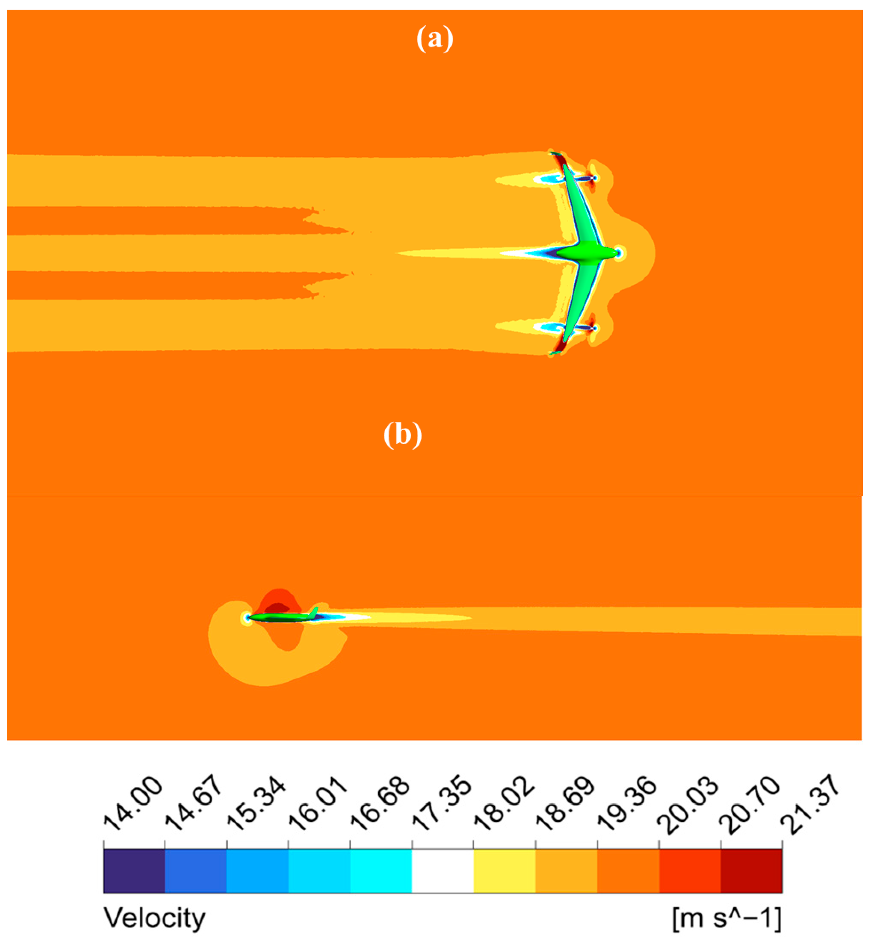
The velocity field shown in
Figure 11 further supports this interpretation. The flow remains predominantly attached over the external surfaces at the nominal cruise condition, while localized acceleration is observed around the forebody and upper wing region. Downstream of the airframe, coherent wake structures develop behind the fuselage, wing trailing edge, and VTOL support elements, confirming that the externally mounted system contributes not only to drag but also to the overall wake topology of the aircraft.
Overall, the full-aircraft cruise simulation defines the preliminary aerodynamic loading baseline of the UAV and provides the baseline pressure field against which the wing-only AoA (Angle of Attack) study and the maneuver/gust-envelope interpretation can be correlated in the following subsections.
3.2. Wing Aerodynamic Response as a Function of Angle of Attack
The supplementary wing-only AoA study characterizes the aerodynamic response of the final wing concept across the incidence range relevant to the maneuver and gust envelope. The most important results to retain are the aerodynamic polars , and , together with the chordwise pressure coefficient distributions extracted at representative spanwise stations.
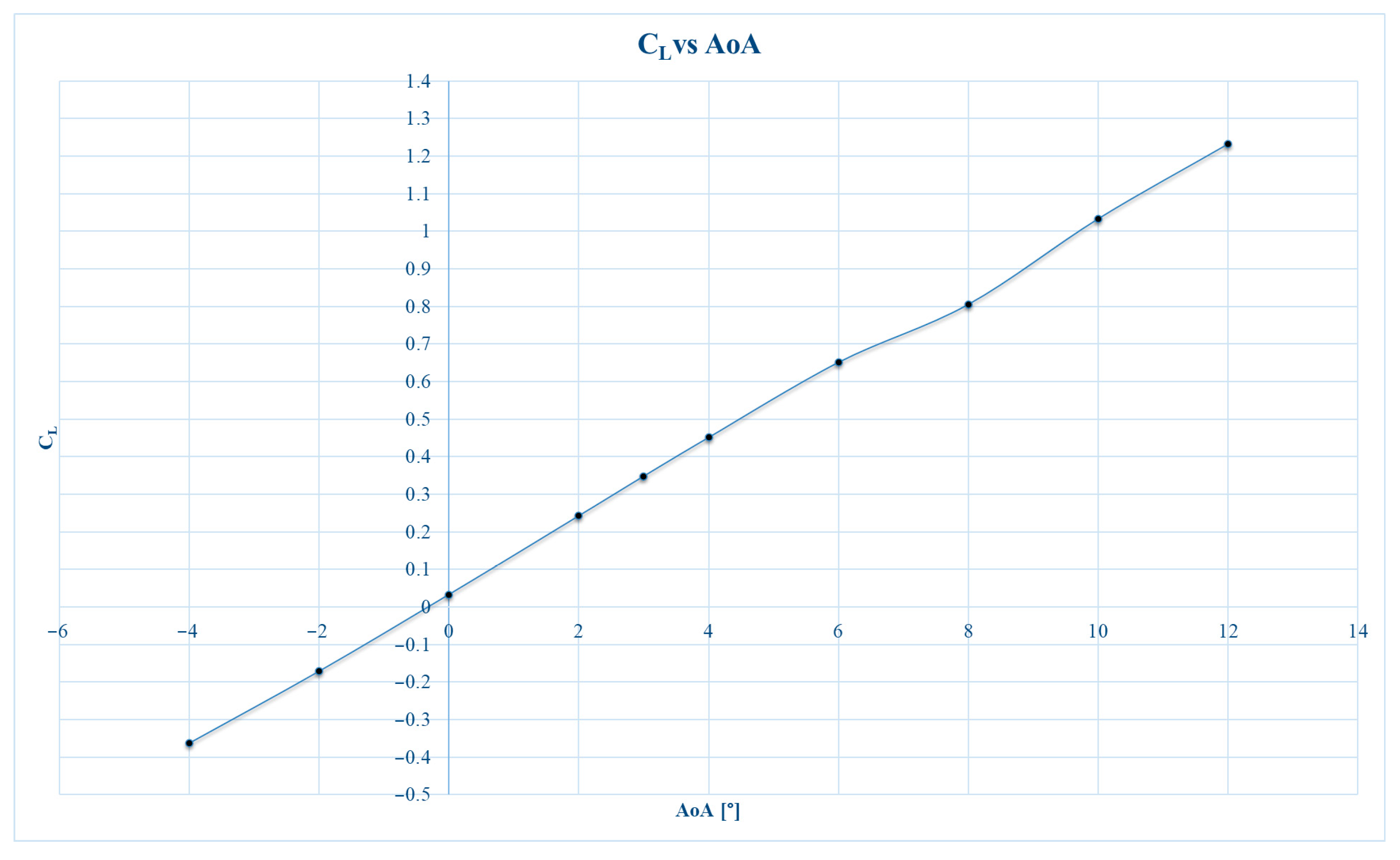
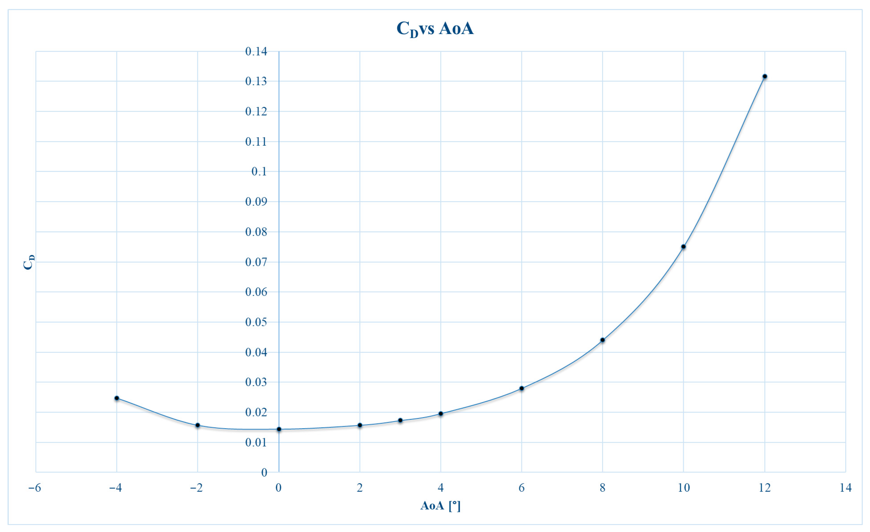
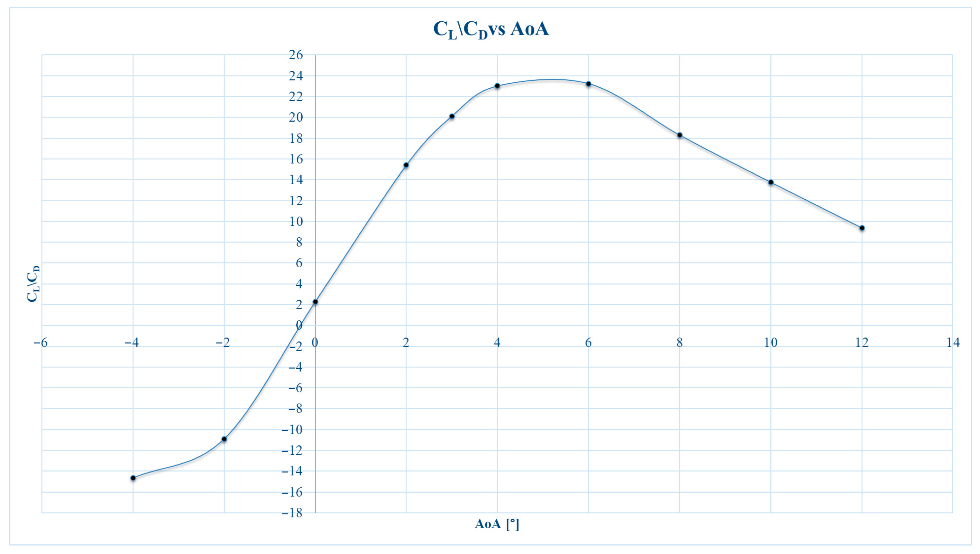
The global aerodynamic behavior of the final wing configuration was assessed through the variation in the lift coefficient, drag coefficient and aerodynamic efficiency with angle of attack. The resulting polars, shown in
Figure 12,
Figure 13 and
Figure 14, provide a compact description of the wing response over the incidence range relevant to cruise, maneuver, and gust induced load amplification. In addition to identifying the most favorable operating interval, these curves establish the aerodynamic basis for interpreting the lift capability, drag growth, and efficiency variation in the selected wing concept.
The lift-coefficient polar exhibits the expected monotonic increase of with angle of attack over the investigated range, indicating a stable lifting response in the pre-stall regime. The - trend remains nearly linear from negative incidences up to the upper part of the analyzed interval, which is consistent with attached-flow aerodynamic behavior. This result confirms that the final wing geometry provides a predictable increase in lift with incidence and maintains a favorable aerodynamic response throughout the operating range considered in the present study. From a design perspective, the curve demonstrates that the wing can supply the lift growth required to support the interpretation of maneuver and gust-related load states.
The drag-coefficient polar shows the typical nonlinear increase of with angle of attack. At low incidence, the wing presents relatively small drag values, with the minimum drag occurring in the vicinity of the near zero angle of attack region. As the angle of attack increases, the drag rises progressively, and the growth becomes significantly steeper at higher incidences. This behavior reflects the increasing aerodynamic penalty associated with stronger loading and more intense pressure gradients over the wing. The trend therefore highlights the range in which the wing remains aerodynamically efficient and also indicates the onset of the less favorable regime in which drag growth begins to dominate the aerodynamic response.
The aerodynamic efficiency curve, expressed through , provides the clearest indicator of the most favorable operating range of the final wing configuration. The efficiency increases rapidly from negative incidence toward moderate positive angles of attack, reaches a maximum, and then decreases gradually as the drag rise becomes more pronounced than the corresponding lift increase. This behavior identifies a moderate positive angle-of-attack interval as the most advantageous operating region of the wing from an aerodynamic standpoint. Consequently, the curve is particularly useful for locating the incidence range associated with the best balance between lift generation and aerodynamic resistance, which is directly relevant to cruise efficiency and low-to-moderate maneuver loading.
While the aerodynamic polars provide the integral response of the wing, they do not directly reveal how the loading is distributed over the surface. For this reason, the analysis was complemented by chordwise pressure-coefficient distributions extracted at representative spanwise stations. These sectional results provide a local interpretation of the aerodynamic behavior summarized by the , , and curves and help identify how the pressure loading evolves from the inboard region toward the wing tip.
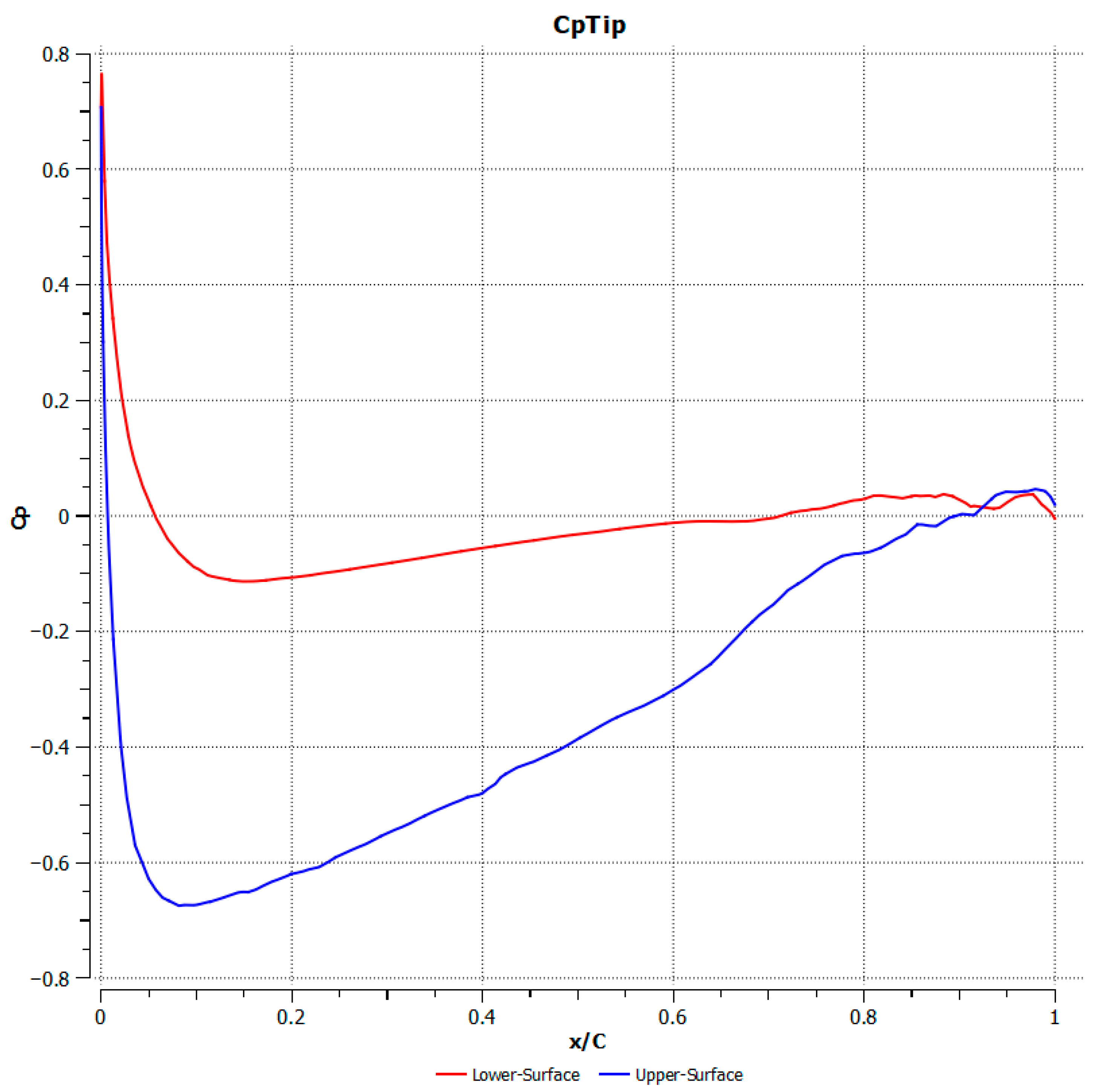
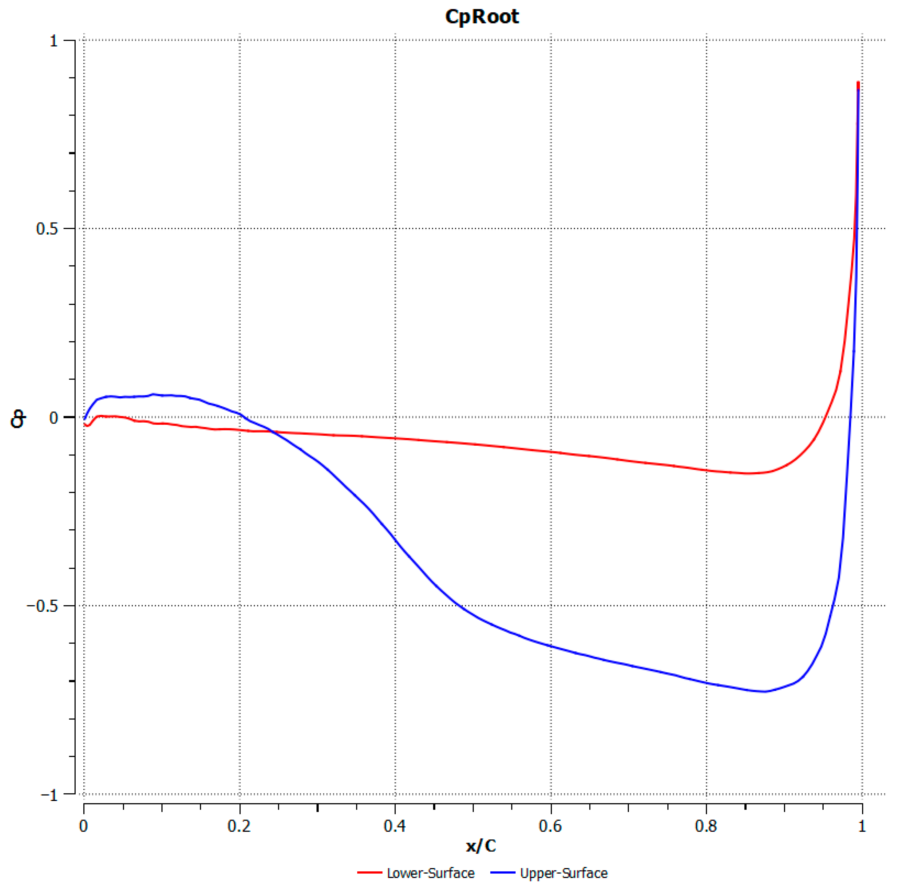
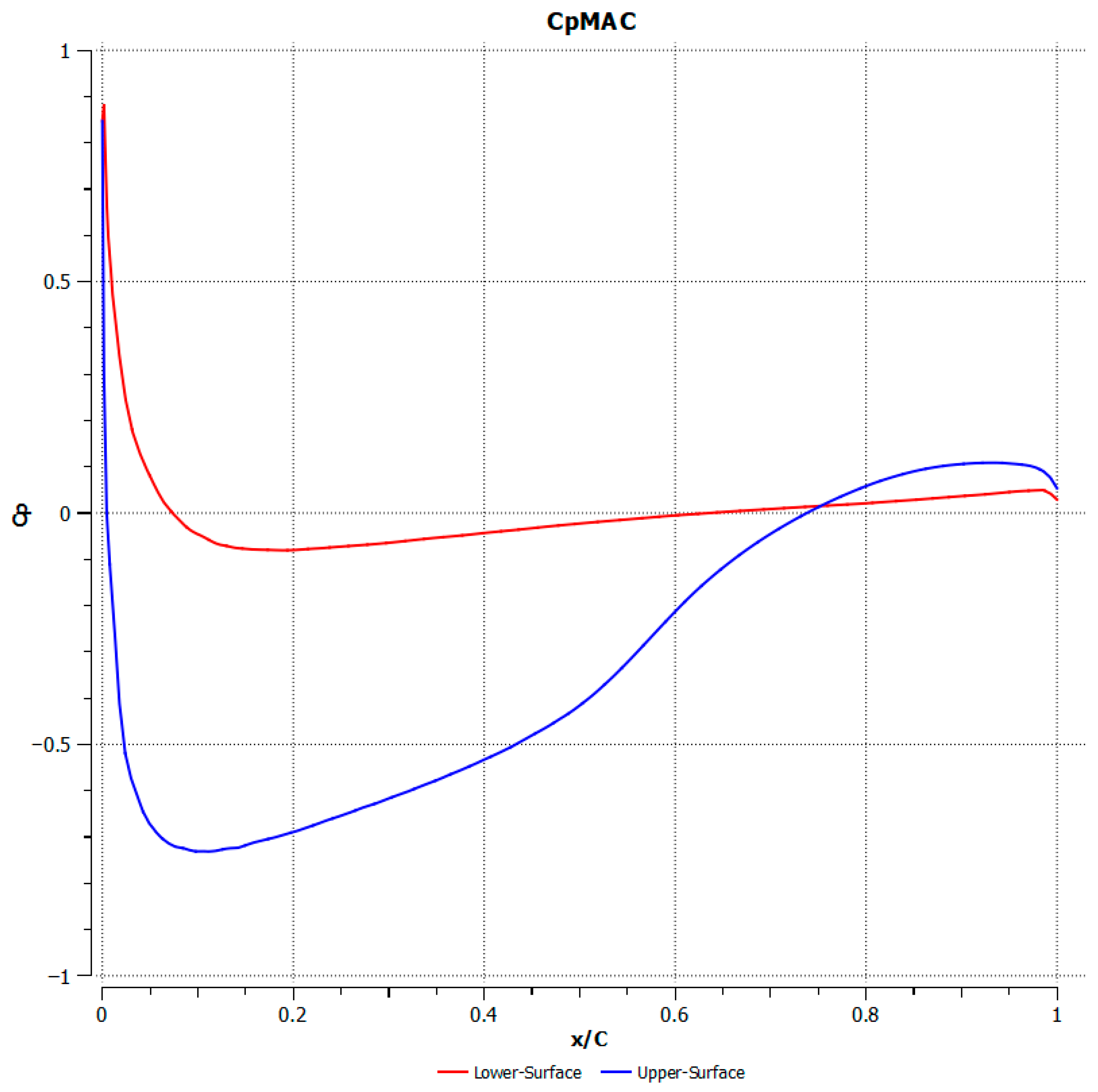
To complement the integral aerodynamic coefficients, the local pressure loading of the final wing configuration was investigated through chordwise pressure coefficient distributions extracted at three representative spanwise stations. The selected sections correspond to the inboard wing region, the MAC location region and the outboard wing region near the wingtip. Presented in
Figure 15,
Figure 16 and
Figure 17, these distributions provide a detailed view of how the sectional aerodynamic loading evolves along the span and allow a more precise interpretation of the global trends identified in the aerodynamic polars.
Figure 15 shows the chordwise pressure coefficient distribution in the inboard wing region. The upper surface exhibits a pronounced negative
peak near the leading edge, indicating strong local suction and therefore a significant contribution to lift generation. Downstream of the leading-edge region, the pressure recovers progressively toward the trailing edge, while the lower surface remains closer to zero and slightly positive over most of the chord. The relatively large separation between upper- and lower-surface curves confirms that the inboard section carries an important fraction of the aerodynamic load. At the same time, the shape of the distribution reflects the influence of three-dimensional effects associated with the wing-root region and the proximity of the fuselage, which makes this section more aerodynamically complex than an isolated two-dimensional airfoil section.
Figure 16 presents the pressure coefficient distribution at the spanwise location associated with the mean aerodynamic chord. This section displays the clearest representative lifting behavior of the wing, with a well-defined suction peak on the upper surface followed by smooth pressure recovery toward the trailing edge. Compared with the inboard region, the distribution is more regular and less affected by strong three-dimensional interference, which makes it particularly suitable for interpreting the characteristic aerodynamic response of the wing at the nominal cruise condition. The pressure difference between the upper and lower surfaces remains substantial over a large portion of the chord, confirming that this region contributes efficiently to the overall lift while maintaining a relatively balanced recovery pattern. For this reason, the MAC location section can be regarded as the most representative local aerodynamic section of the wing.
Figure 17 shows the pressure-coefficient distribution in the outboard wing region, near the tip. The upper surface still exhibits a clear suction peak close to the leading edge, but the overall pressure difference between upper and lower surfaces is slightly reduced compared with the inboard and MAC-location sections. This behavior is consistent with the expected spanwise relief of aerodynamic loading toward the tip and reflects the influence of finite-wing effects in the outer part of the wing. The pressure recovery remains gradual and physically consistent, although the distribution is slightly more sensitive to local three-dimensional effects and tip-region flow structures. Even so, the section continues to display a stable lifting response, confirming that the outboard wing contributes effectively to the overall aerodynamic performance while carrying a somewhat lower local load than the inboard and central regions.
Taken together, the sectional distributions confirm that the wing loading is not uniform along the span. The inboard region carries a comparatively stronger and more complex load due to wing-body interaction, the MAC-location section reflects the most representative local aerodynamic behavior of the wing, and the outboard region shows the expected reduction in sectional loading associated with finite-wing effects. These results are fully consistent with the global aerodynamic polars and provide a local pressure-based interpretation of the lift generation mechanism of the final wing configuration.
3.3. Correlation Between Aerodynamic CFD Results and the Maneuver/Gust Envelope
The maneuver and gust envelopes define the critical load-factor limits of the UAV, but they do not directly indicate the aerodynamic state associated with each design point. In order to establish this link, the critical points extracted from the maneuver and gust diagrams were correlated with the aerodynamic CFD results obtained for the final wing configuration. For each selected point, the corresponding required lift coefficient was determined from the associated flight speed and load factor, after which the wing lift polar was used to estimate an equivalent angle of attack. In this way, each critical maneuver or gust condition can be interpreted not only as a structural design load, but also as an aerodynamic state characterized by a required lift level and an equivalent incidence range.
For each critical point of the maneuver and gust envelopes, the aerodynamic state was determined by converting the corresponding load factor into an equivalent lift requirement. This was achieved by expressing the lift coefficient necessary to sustain the prescribed load factor at the corresponding flight speed, and then mapping this value onto the CFD derived wing lift polar.
where
n—the load factor corresponding to the selected maneuver or gust point
W—aircraft weight
—air density
V—flight speed
S—wing reference area
The equivalent angle of attack
was subsequently determined from the CFD derived lift polar
through linear interpolation between the neighboring calculated points.
Based on the procedure described above, a set of representative maneuver and gust points was converted into equivalent aerodynamic states. The resulting correlation between speed, load factor, required lift coefficient, and equivalent angle of attack is summarized in
Table 5.
For envelope points outside the investigated aerodynamic range , the corresponding angle-of-attack indication is shown only as an out-of-range extrapolated estimate and is not interpreted as a physically resolved post-stall or high-incidence aerodynamic state.
The results indicate that the nominal cruise condition corresponds to a required lift coefficient of approximately , which maps to an equivalent angle of attack of about . This value is consistent with the moderate positive-incidence range previously identified as aerodynamically favorable for the final wing configuration. The positive maneuver limit point B corresponds to a substantially higher aerodynamic demand, with and an equivalent angle of attack of approximately , placing the wing close to the upper end of the investigated pre-stall range. By contrast, the positive gust case at dive speed remains within the investigated aerodynamic range, with and , indicating that this high-speed gust condition can still be interpreted within the steady CFD envelope of the wing.
Several of the envelope points fall outside the lift-coefficient and angle-of-attack interval directly covered by the wing CFD polar, and any continuation beyond that range should therefore be interpreted only as an extrapolated indication of severity rather than as a physically resolved aerodynamic state. In particular, the positive gust case at requires , corresponding to an out-of-range high-incidence condition beyond the investigated steady pre-stall interval. Similarly, the negative maneuver and negative gust points lead to incidences below the lower bound of the calculated aerodynamic polar. These cases should therefore be interpreted only as extrapolated indicators of aerodynamic severity rather than as resolved aerodynamic states directly supported by the investigated CFD polar. Consequently, the correlation is most defensible only for those points that fall within the investigated lift-coefficient range of the wing CFD study. For the out-of-range positive gust and negative-load cases, the present results should be interpreted only as preliminary indicators of structural severity, not as a direct aerodynamic basis for final material-selection conclusions. In the present work, the CFD-based wing polar was evaluated in the interval , and values outside this range were treated as extrapolated.
While the wing-only angle of attack study provides the aerodynamic mapping between required lift coefficient and equivalent incidence, the full-aircraft cruise CFD solution remains the reference distributed-loading case for the actual UAV configuration. The latter includes the influence of the fuselage and externally mounted VTOL system and therefore captures the configuration-level pressure distribution associated with the nominal operating condition. Accordingly, the present correlation should be interpreted as a quasi-steady bridge between certification-based envelope loads and CFD-derived aerodynamic states, rather than as a direct transient gust simulation.
Overall, this correlation confirms that the cruise and several critical positive-load cases remain compatible with the aerodynamic behavior identified by the CFD study, while the most severe positive and negative gust points exceed the directly investigated steady incidence range and should therefore be treated as extrapolated envelope conditions for preliminary design assessment.
Accordingly, the subsequent material-selection discussion should be understood primarily with respect to the cruise condition and those positive-load cases that remain within the investigated aerodynamic range, while the most severe extrapolated gust and negative-load points remain outside the directly resolved aerodynamic basis of the present study.
For this reason, the out-of-range positive gust and negative-load points are retained only to illustrate envelope severity and the limits of the present quasi-steady aerodynamic assessment, not to establish resolved aerodynamic design states.
3.4. Experimental Mechanical Properties of CFRP Laminates
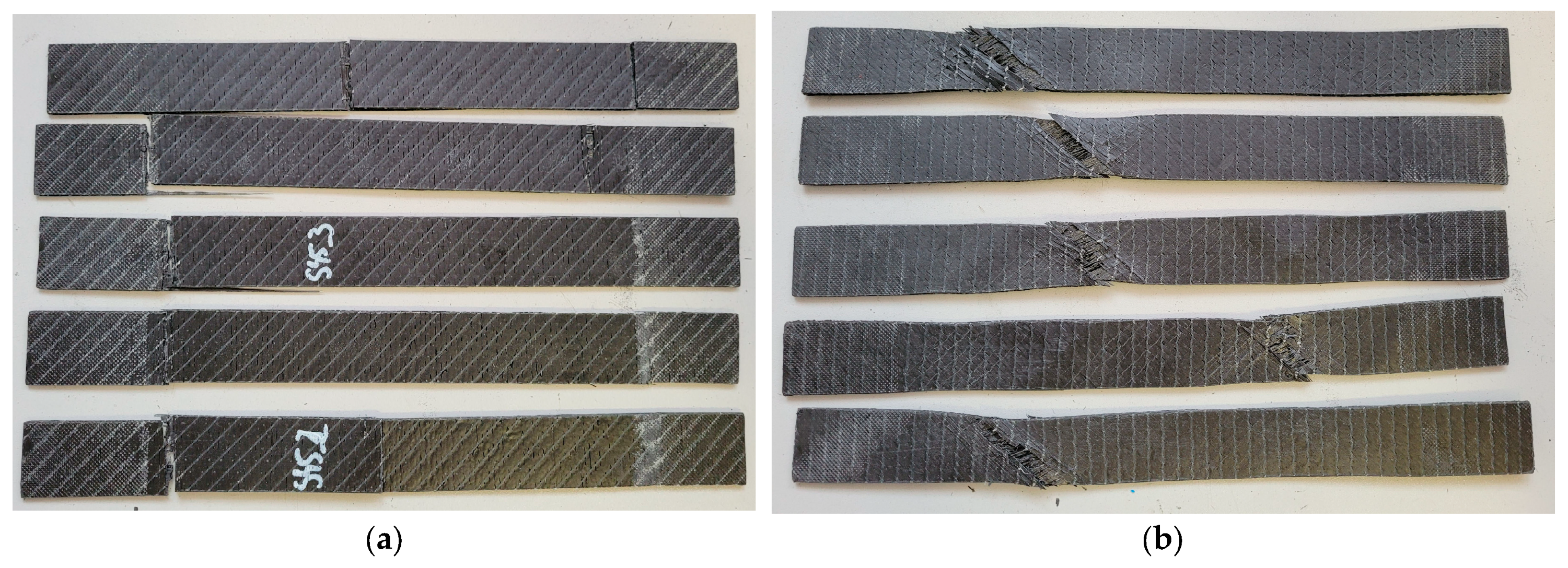
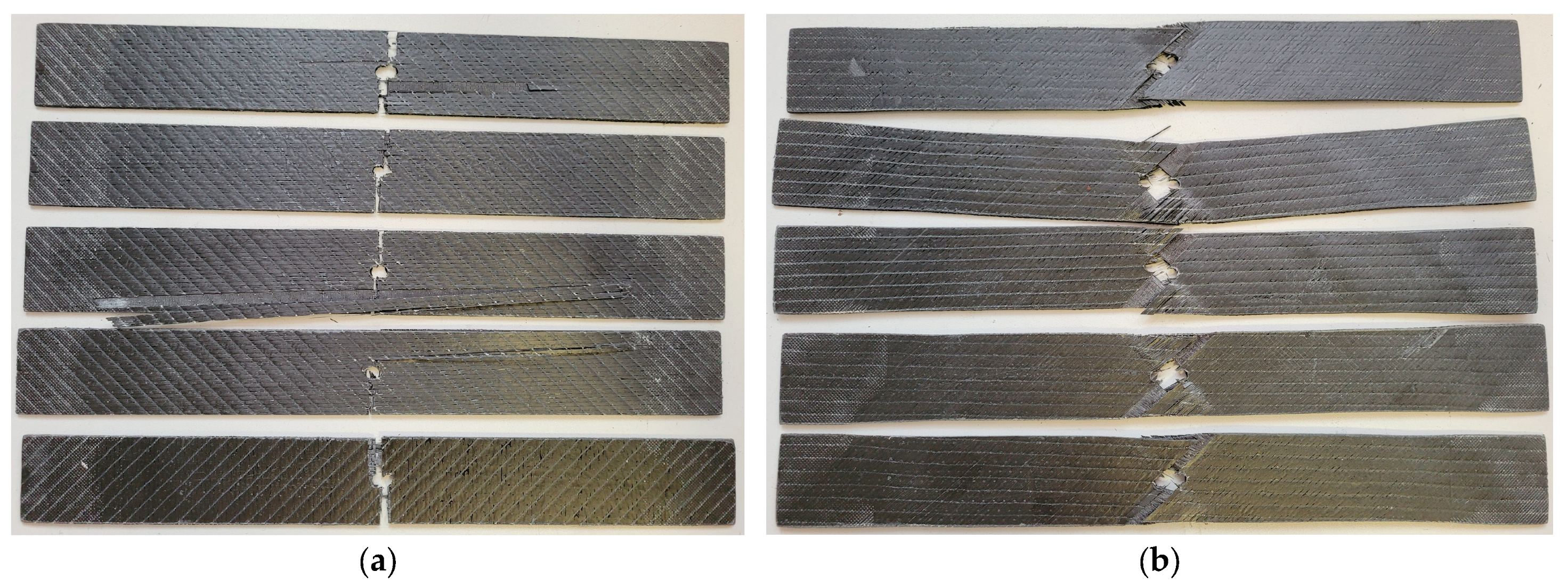
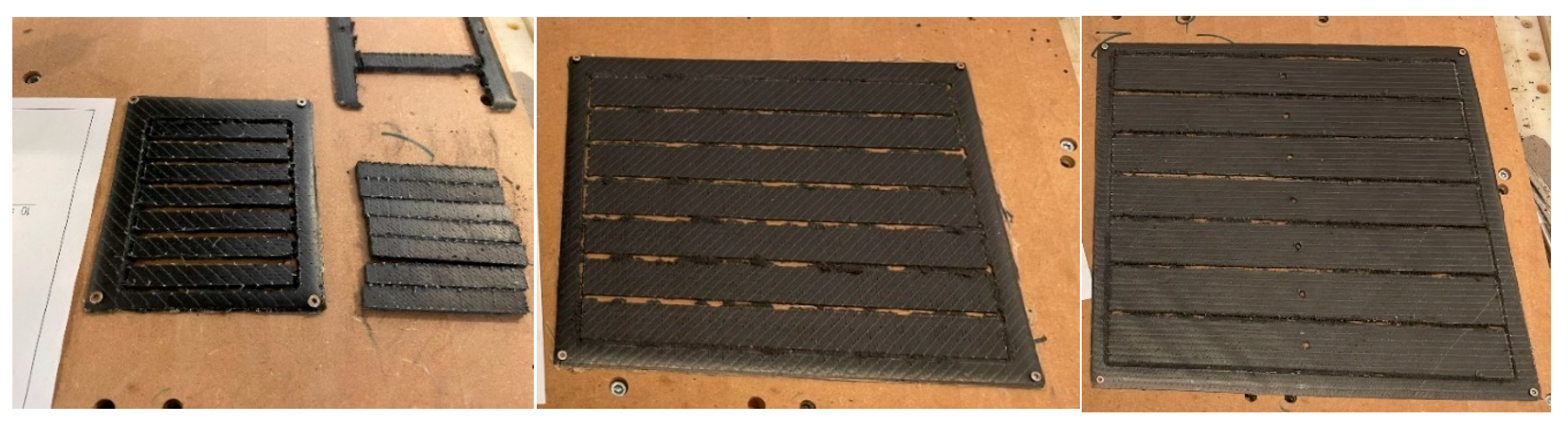
The experimental tensile tests revealed distinct failure modes depending on the CFRP laminate stacking sequence, and the presence of geometric discontinuities. Representative post-failure appearances of the tested specimens are presented in
Figure 18,
Figure 19 and
Figure 20 to illustrate the dominant damage mechanisms observed under monotonic tensile loading.
Compared to the solid specimens, the introduction of an open hole led to a clear localization of damage and a modification of the failure pattern, particularly for the CFRP laminates, as shown in
Figure 19.
Table 6 summarizes the failure modes of the CFRP tensile specimens, classified according to ASTM D3039 and ASTM D5766 standards. The results highlight the influence of stacking sequence and the presence of stress concentrators on the failure behavior.
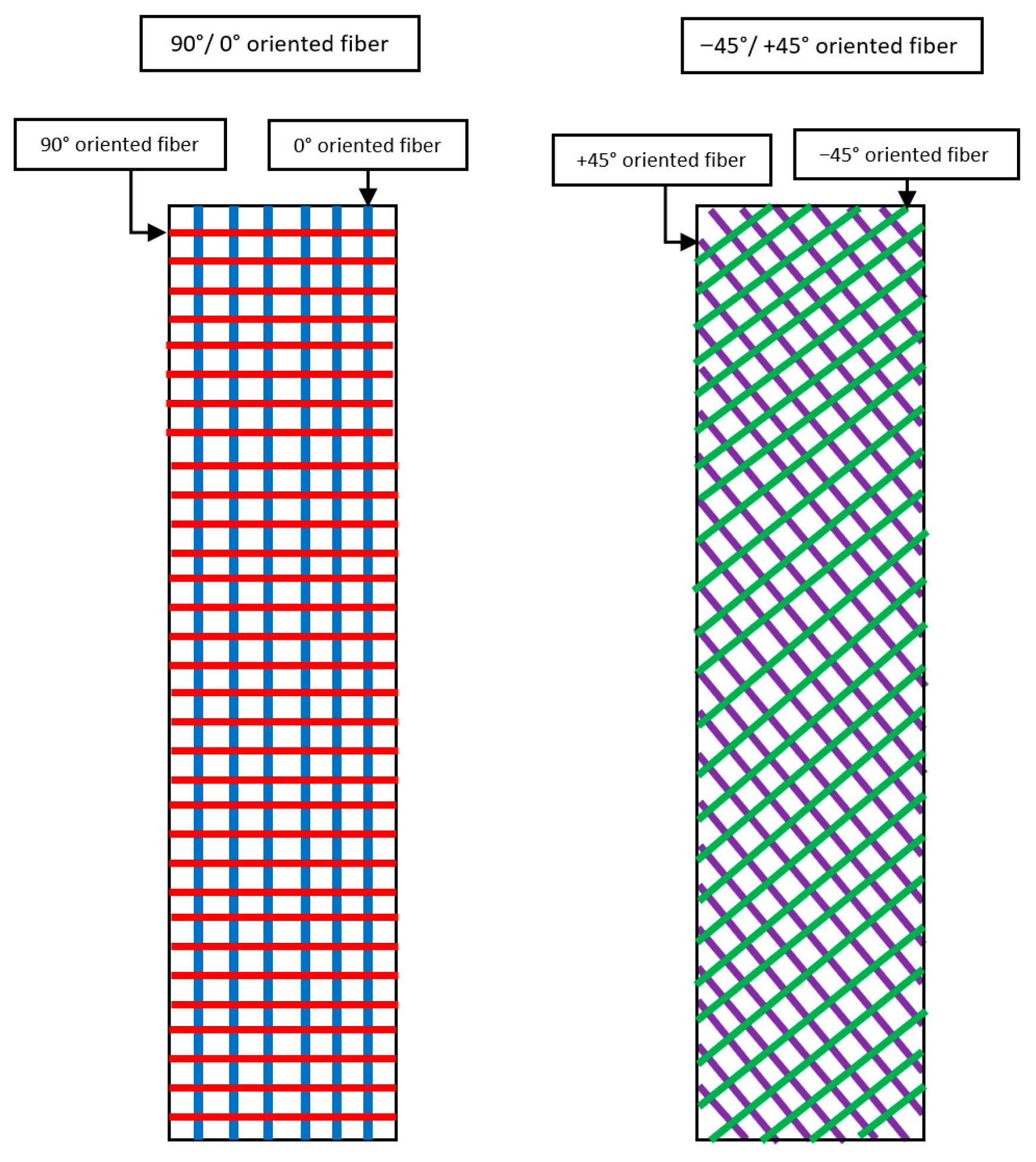
While solid laminates exhibit a wider variability of failure modes, ranging from lateral and splitting to multi-mode and explosive failure, the open-hole specimens show a more consistent and repeatable behavior. Specifically, the [0/90] configuration is characterized by a lateral failure mode (LGM), whereas the [−45/+45] laminates predominantly fail through an angled mechanism (AGM), indicating a transition from fiber-dominated to shear-dominated failure.
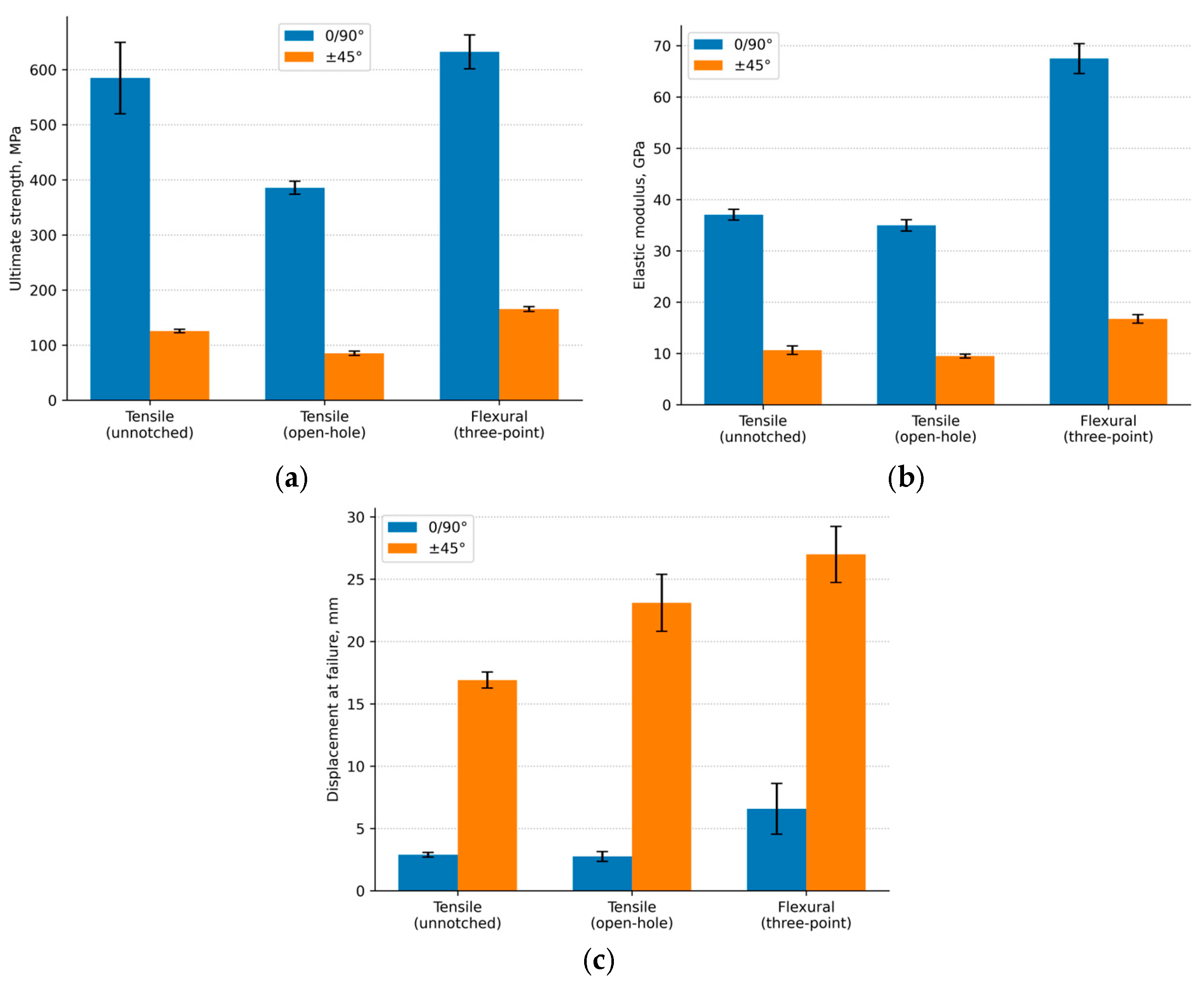
Figure 20 illustrates the variation in mechanical properties of CFRP laminates as a function of stacking sequence and loading configuration. The comparison highlights the combined effects of fiber orientation and the presence of stress concentrators (open-hole) on strength, stiffness, and deformation behavior.
The average mechanical properties of the investigated CFRP laminate configurations under different loading conditions are summarized in
Table 7.
A clear functional distinction can be observed between the two laminate configurations. The CFRP [0°/90°] laminate exhibited substantially higher strength and stiffness under all investigated loading conditions, reaching average values of 584.81 MPa and 37.06 GPa in tensile loading, 385.63 MPa and 34.99 GPa in open-hole tensile loading, and 632.26 MPa and 67.50 GPa in flexural loading. By contrast, the CFRP [−45°/+45°] laminate showed markedly lower average strength and modulus, with corresponding values of 125.49 MPa and 10.64 GPa in tensile loading, 85.25 MPa and 9.50 GPa in open-hole tensile loading, and 165.45 MPa and 16.74 GPa in flexural loading. However, the [−45°/+45°] configuration exhibited consistently higher deformation capacity, with average elongation or displacement at failure of 16.91 mm in tensile loading, 23.11 mm in open-hole tensile loading, and 26.99 mm in flexural loading, compared with 2.89 mm, 2.76 mm, and 6.58 mm, respectively, for the [0°/90°] laminate. These results confirm that the [0°/90°] configuration is the more suitable of the two investigated lay-ups for primary load-bearing wing regions, whereas the [−45°/+45°] configuration is better interpreted as a more compliant off-axis laminate for secondary or locally shear-dominated regions.
The presence of the open hole led to a clear reduction in ultimate strength for both laminate configurations, confirming the expected sensitivity of the material response to stress concentrations and structural discontinuities. The reduction was more pronounced in absolute terms for the [0°/90°] laminate, although this configuration still retained substantially higher strength and stiffness than the [−45°/+45°] lay-up.
4. Discussion
In addition to the aerodynamic interpretation, the distributed pressure field obtained from the CFD analysis was transferred to a structural finite-element model of the internal wing architecture in order to verify the response of the spars, ribs, and supporting members under representative aerodynamic loading.
The present study was conceived primarily as a preliminary material selection methodology for a hybrid tri-rotor VTOL fixed-wing UAV wing, rather than as a completed full structural verification of the final airframe. In this context, the maneuver and gust envelopes, the full aircraft CFD results, the wing-only aerodynamic analysis, and the experimental laminate characterization must be interpreted as complementary elements of the same selection workflow.
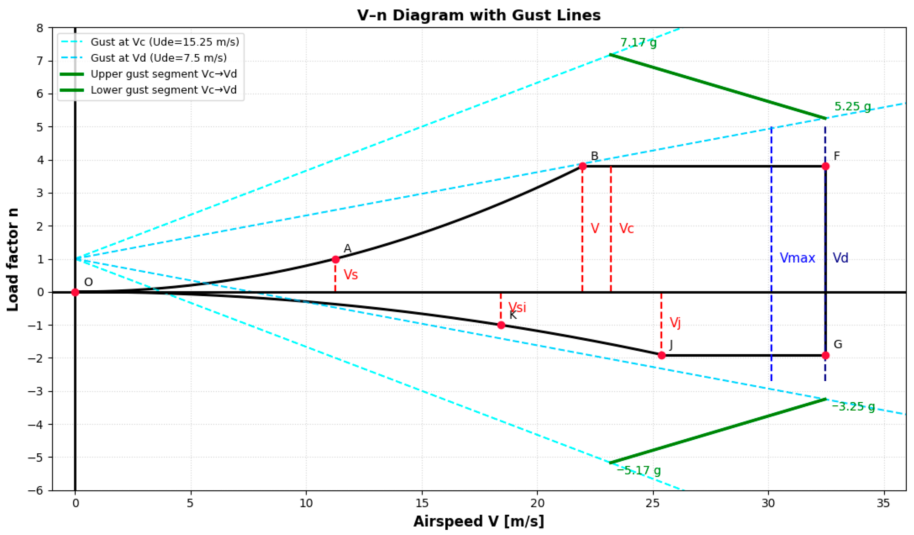
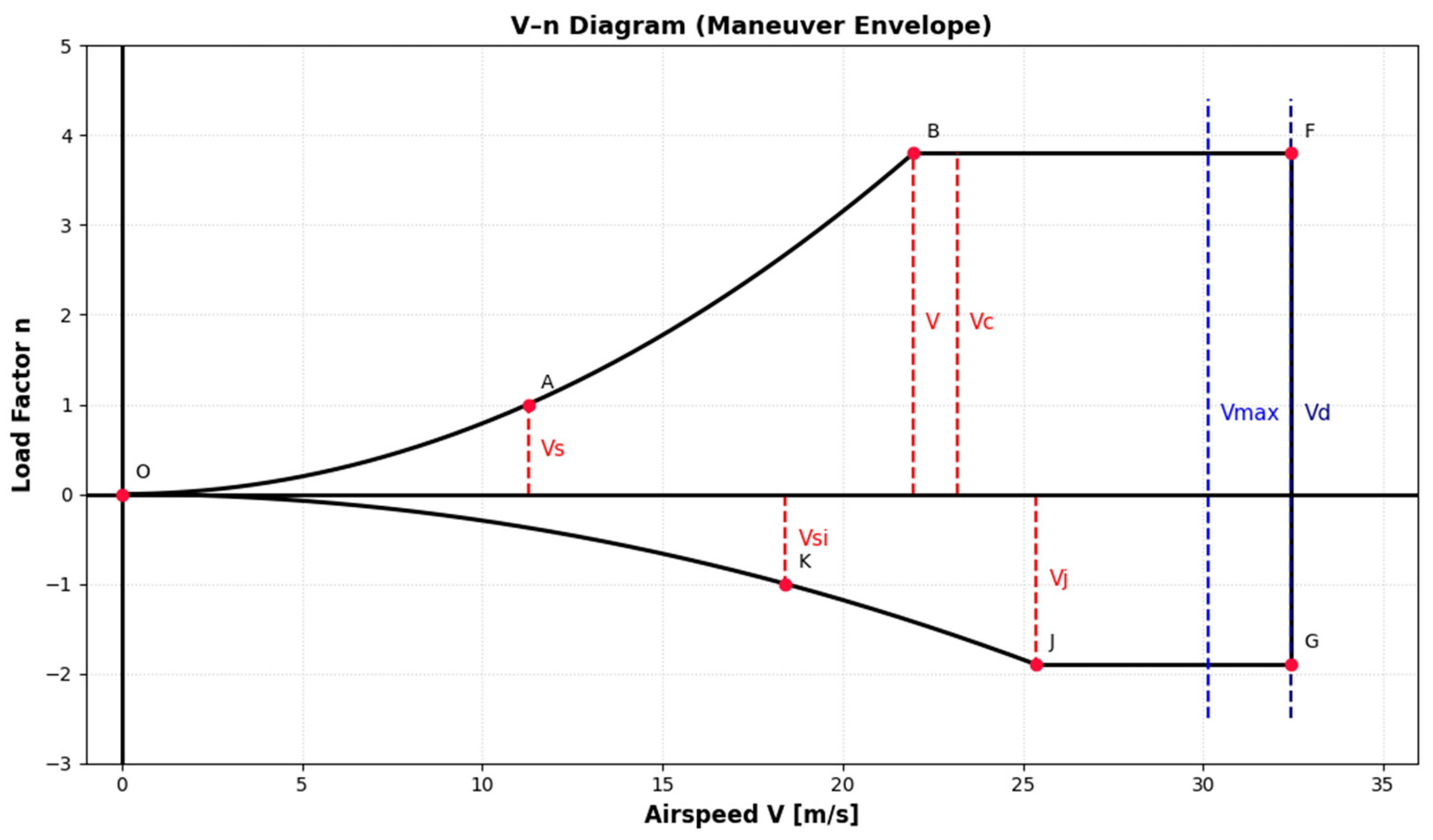
First, the maneuver and gust diagrams define the severity of the load environment to which the wing structure must be exposed. These diagrams identify the critical positive and negative load factors and therefore establish the design space within which the wing must safely operate. However, load factors alone do not describe the actual aerodynamic state of the wing. For this reason, the certification-based envelope results were correlated with the CFD aerodynamic results in order to convert the critical points of the V–n and gust diagrams into equivalent aerodynamic requirements expressed through lift coefficient, equivalent angle of attack, and representative pressure-loading tendencies. In this way, the flight envelope was not treated only as a regulatory diagram, but as the starting point for a material-oriented structural design logic.
Second, the full-aircraft CFD simulation at the nominal cruise condition established the preliminary CFD-based aerodynamic loading baseline of the actual UAV configuration. The resulting aerodynamic coefficients and surface pressure distributions showed that the wing is the dominant lifting component, while the fuselage and externally mounted VTOL system introduce additional drag and local interference effects. These results are important for material selection because they define the type of structural demand expected in service: global wing bending associated with positive lift, local pressure gradients near the wing-body junction, and configuration-induced load redistribution in the inboard region. The cruise solution therefore provides the configuration-level loading baseline against which the role of the wing material can be interpreted.
For a hybrid tri-rotor VTOL configuration, it is also important to recognize that the transition phase between vertical and forward flight may introduce additional aerodynamic and structural complexities beyond those captured by the present cruise-centered and quasi-steady envelope-based analysis. During rotor tilting and propulsion reconfiguration, the wing may experience transient slipstream interaction, locally modified dynamic-pressure distributions, time-varying flow interference from the VTOL supports and propulsive system, and temporary changes in load transfer between lifting and propulsive components. These effects may alter the instantaneous loading distribution relative to the nominal cruise case, especially in the inboard wing region and near the structural supports. Although such transition-regime phenomena were not analyzed in the present study, they represent an important next step for extending the methodology toward a more complete hybrid-VTOL structural design framework.
Third, the supplementary wing-only angle-of-attack analysis clarified how the selected wing responds as the aerodynamic demand increases. The curve confirmed a stable lift growth in the investigated pre-stall range, while the and trends identified the most favorable aerodynamic operating interval. The sectional distributions extracted at the inboard, MAC-location, and outboard regions further showed that the wing loading is not uniform along the span. The inboard region is more strongly influenced by three-dimensional and wing-body interference effects, whereas the outboard region experiences a lower local pressure difference, consistent with finite-wing load relief. From the structural point of view, this means that the candidate material for the primary wing structure must primarily withstand bending-dominated loading, with the most severe demands expected in the inboard and central wing regions.
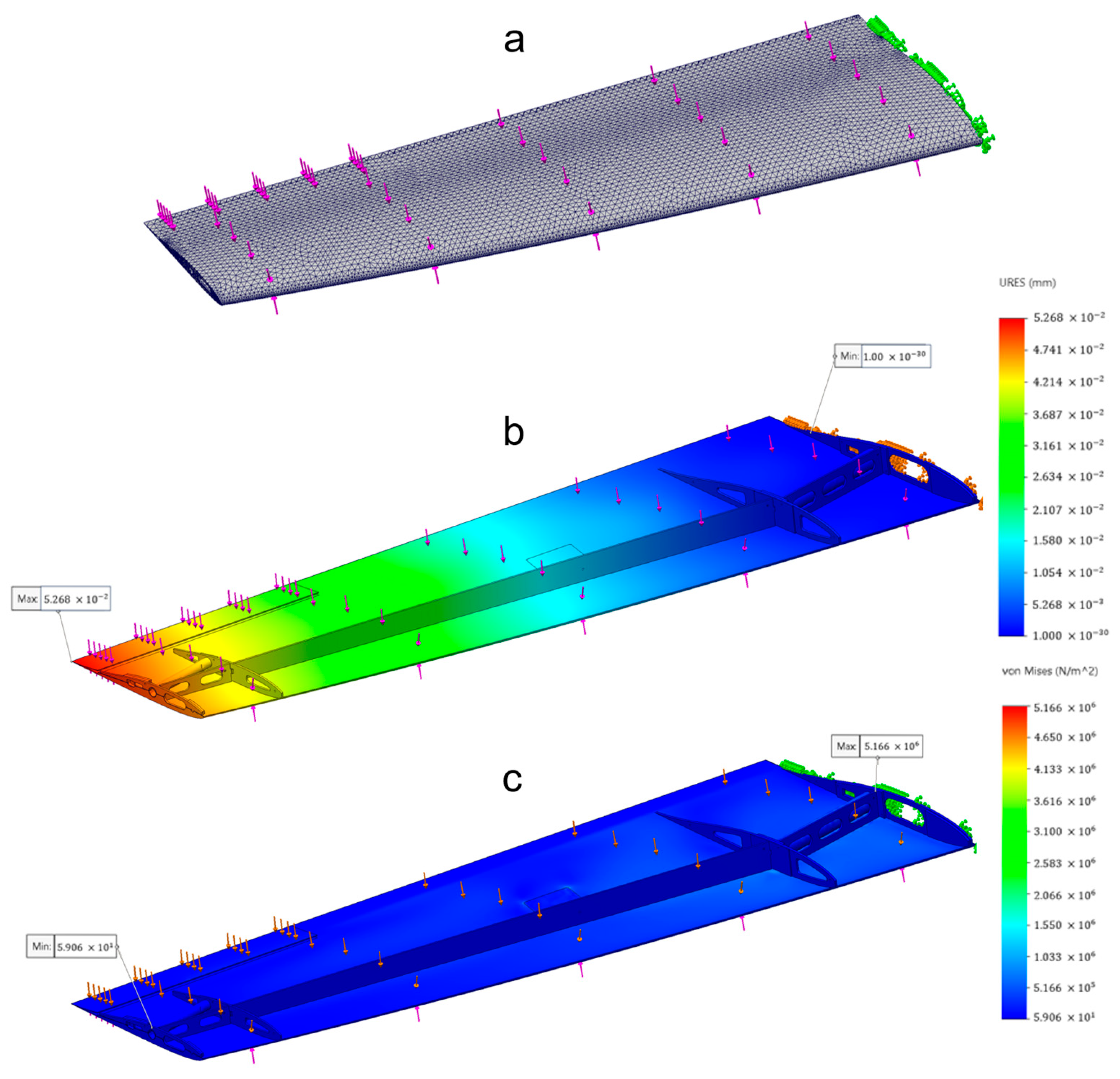
To further support the structural interpretation of the aerodynamic results, the pressure field obtained from the CFD analysis on the wing intrados and extrados was transferred as distributed loading to a finite-element model of the internal wing structure in SolidWorks Simulation 2025 (Dassault Systèmes, Vélizy-Villacoublay, France). This one-way CFD-to-FEA step was introduced to verify how the identified aerodynamic loading is transmitted through the primary internal load-carrying members, including spars, ribs, and supporting regions, and to confirm whether the resulting structural response is consistent with the bending-dominated demand inferred from the maneuver/gust envelope and the aerodynamic pressure distributions.
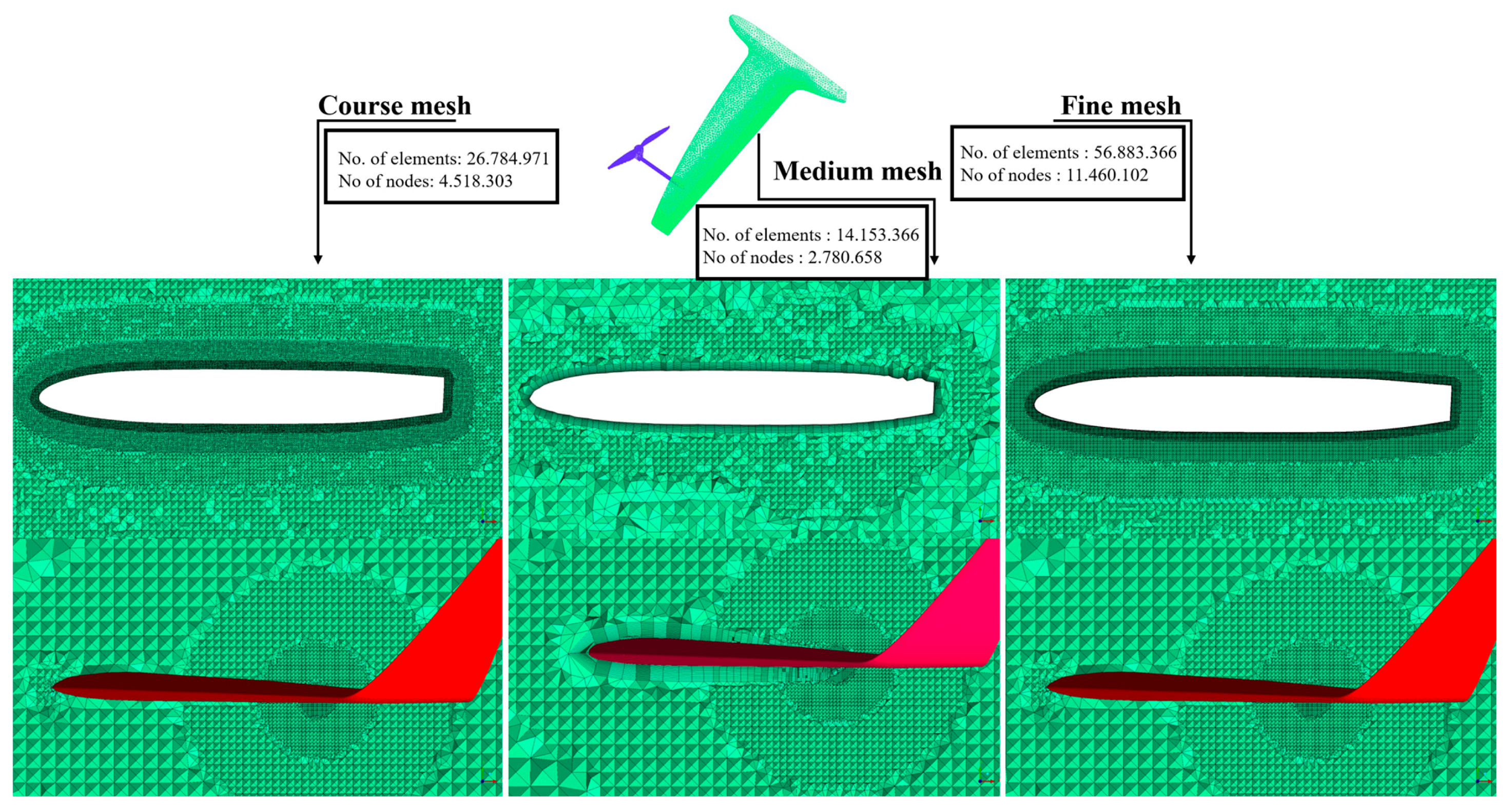
The structural model was discretized using a finite-element mesh comprising 103,757 elements and 212,541 nodes. The numerical grid density is relatively uniform over the wing surface, with sufficient refinement in structurally critical areas, particularly near the wing root and along the leading and trailing edges, in order to capture the stress and deformation fields adequately in a linear static analysis. A fixed-support boundary condition was imposed at the wing root to represent the rigid connection between wing and fuselage, while the aerodynamic loads derived from the CFD solution were applied as distributed loads on the wing surfaces.
The structural response of the wing under CFD-derived aerodynamic loading is illustrated in
Figure 21.
The structural response obtained from the one-way CFD-to-FEA transfer is fully consistent with a cantilever-type wing under distributed aerodynamic loading. The total-displacement field shows a continuous increase in deformation from the root toward the free end, with a maximum displacement of approximately 5.27 × 10⁻² mm at the wing tip and practically zero displacement at the fixed root, confirming the correct application of the boundary conditions. The Von Mises stress distribution shows the highest stress level near the wing root, reaching approximately 5.17 × 10⁶ N/m2, which is physically consistent with the highest bending moments occurring in the root region. Away from the root, both the displacement and stress fields remain smooth and moderate, including in the rib- and spar-supported regions, indicating that the aerodynamic loads are transferred coherently through the internal structure and that the dominant structural demand is indeed root-dominated bending rather than localized instability in the outboard region.
Although this one-way CFD-to-FEA step does not yet provide a full structural sizing framework in terms of spanwise bending-moment diagrams, shear-force distributions, laminate failure indices, or classical laminate theory-based reserve factors, it does provide a quantitative structural link between the distributed aerodynamic loading and the observed root-dominated bending response of the wing.
Within this framework, the role of the experimental material campaign becomes more explicit. The maneuver/gust envelope defines the severity of the load environment, the CFD analyses identify the dominant aerodynamic state and spanwise pressure-loading tendencies, and the one-way CFD-to-FEA transfer confirms that these aerodynamic loads produce a structural response dominated by root bending and axial/flexural demand in the primary wing structure. On this basis, tensile, open-hole tensile, and three-point bending tests remain the most relevant experimental indicators because they correspond directly to the main structural modes expected in the wing, namely axial load transfer, flexural resistance, and robustness in the presence of local discontinuities. The resulting load-informed laminate-selection rationale is summarized in
Table 8.
As shown in
Table 8, the usefulness of the experimental campaign does not lie merely in confirming that different laminate architectures exhibit different generic behaviors, but in determining which experimentally verified response is the most appropriate for the specific aerodynamic and structural load environment of the present UAV wing. The aerodynamic analyses identify a design problem dominated primarily by bending-induced axial and flexural demand, especially in the inboard and root regions, while the one-way CFD-to-FEA structural transfer confirms that the distributed aerodynamic pressure field produces the highest stress levels near the root and a cantilever-type deformation pattern of the internal wing structure. Under these conditions, the screening campaign demonstrates not only that the [0°/90°] laminate is stronger and stiffer, but also that these properties are consistent with the root-bending-dominated structural response identified by the CFD-to-FEA transfer. Conversely, the [−45°/+45°] laminate remains relevant because it defines a contrasting off-axis response that may still be useful in secondary or locally shear-dominated regions. In this sense, the experimental campaign helps establish the correspondence between aerodynamic demand, structural response, and laminate capability, rather than simply reproduce a generic ranking of laminate families.
It is important to note, however, that this load-informed interpretation is most directly supported for the nominal cruise condition and the positive-load cases that remain within the investigated aerodynamic range of the wing CFD study. The extrapolated positive gust condition at and the negative-load cases are retained only as indicators of potentially severe loading and of the limits of the present quasi-steady aerodynamic assessment; they are not used here as fully resolved aerodynamic states for definitive material-selection ranking.
From this perspective, the superiority of the [0°/90°] CFRP laminates is not merely a generic material result, but a direct consequence of the expected aerodynamic loading regime. Since the UAV wing is primarily required to resist bending-induced tensile and compressive stresses, together with sufficient flexural stiffness to limit deformation, the material with the highest tensile strength, highest bending strength, and most favorable stiffness response is the preferred candidate within the two investigated laminate configurations for the main load-bearing regions. The experimental results show that the [0°/90°] CFRP laminate provides the more favorable response within the investigated screening set. By contrast, the [−45°/+45°] lay-up exhibits larger deformation capability but lower axial and flexural performance, which makes it less suitable for the primary spar-cap or skin regions responsible for carrying the dominant aerodynamic bending loads.
The same reasoning also highlights that material selection should be driven by the specific aerodynamic loading regime rather than by general material characteristics such as compliance or manufacturability. The aerodynamic loading environment identified by the envelope and CFD results points toward a design problem governed by stiffness and strength efficiency. Under such conditions, CFRP [0°/90°] provides the more suitable match within the two investigated laminate families between load demand and material resistance. In other words, the material selection is not based only on the absolute ranking of experimental properties, but on how those properties correspond to the load modes imposed by the aerodynamic environment of the UAV.
A further limitation of the experimental campaign is that the cured laminates were not quantitatively characterized in terms of fiber volume fraction or void content. Accordingly, although the mechanical comparisons reported in
Section 3.4 remain useful as laminate-level screening results for coupons manufactured under the same material system and nominal process route, the present study does not establish a direct processing–structure–property correlation based on quantified consolidation metrics. Future work should therefore include fiber volume fraction and porosity measurements in order to strengthen the interpretation of the experimental mechanical response.
The methodology proposed in this work can therefore be summarized as follows: the maneuver and gust envelopes identify the critical load-factor conditions; the CFD analyses translate these conditions into aerodynamic states and distributed loading tendencies; and the mechanical tests identify the laminate configuration showing the more favorable response for the identified structural demands. In this sense, the present work establishes a load-informed material-selection methodology for preliminary wing design.
At the same time, it is important to state clearly that this methodology remains at a preliminary design level. The present approach assumes quasi-steady aerodynamic behavior and does not account for transient or aeroelastic effects, which may become relevant under severe gust conditions At the same time, it is important to state clearly that this methodology remains at a preliminary design level. Although a one-way CFD-to-FEA transfer was performed in order to verify the structural response of the wing under representative aerodynamic loading, the present approach still assumes quasi-steady aerodynamic behavior and does not include detailed composite failure indices, reserve-factor assessment, progressive damage, or coupled aeroelastic effects. The present results should therefore be interpreted as a rational basis for preliminary material selection and structural interpretation prior to detailed sizing and full structural verification under the most severe maneuver and gust conditions.
At the same time, the present study should still be interpreted as a preliminary load-informed laminate-screening framework rather than a complete structural verification or optimization methodology. A more rigorous next step would involve explicit structural resultants, simplified beam-theory or classical laminate-theory calculations, and laminate-level failure assessment under the most severe aerodynamic cases.
5. Conclusions
This study presented a flight-envelope-based preliminary design methodology for a hybrid tri-rotor VTOL fixed-wing UAV, combining maneuver/gust-envelope calculation, full-aircraft and wing-only CFD analysis, and experimental composite-material characterization.
The main conclusions are as follows:
The maneuver and gust envelopes defined a clear set of critical operational load cases for the investigated UAV configuration and provided the certification-oriented basis for aerodynamic and structural interpretation.
The full-aircraft CFD simulation at the nominal cruise condition established a preliminary CFD-based aerodynamic loading baseline for the real UAV configuration, yielding global aerodynamic coefficients and distributed pressure fields that captured the interference effects of the fuselage and externally mounted VTOL system.
The wing-only angle-of-attack study showed that the final wing configuration presents a stable pre-stall lift response, a progressively increasing drag penalty at higher incidences, and a moderate positive-incidence interval associated with the most favorable aerodynamic efficiency.
The sectional Cp distributions confirmed that wing loading is not uniform along the span: the inboard region is more strongly affected by configuration-level three-dimensional effects, the MAC-location section provides the most representative local lifting behavior, and the outboard region exhibits the expected reduction in sectional loading toward the tip.
The correlation between the aerodynamic results and the maneuver/gust envelope demonstrated that the nominal cruise condition and several critical positive-load cases fall within the investigated steady aerodynamic range of the wing, whereas the most severe positive gust and the negative-load cases lie outside that range and must therefore be treated as extrapolated aerodynamic states.
The experimental mechanical characterization demonstrated that the [0°/90°] CFRP laminate configuration provides the best combination of strength and stiffness for primary load-bearing wing applications within the preliminary load environment directly supported by the investigated aerodynamic range, whereas the [−45°/+45°] configuration remains more suitable for secondary or locally shear-dominated regions.
Overall, the proposed workflow provides a preliminary aerodynamic and material basis for hybrid VTOL UAV wing design, linking certification-based load definition, CFD-derived aerodynamic loading estimates within the investigated range, and experimentally characterized material performance.
A limitation of the present study is that the aerodynamic CFD results were not directly validated against experimental or benchmark aerodynamic data for the analyzed configuration; future work should therefore include such validation in order to consolidate the aerodynamic loading basis used for structural sizing and material selection.
This work contributes to bridging the gap between aerodynamic load characterization and material-informed structural design in hybrid UAV configurations.
Future work will focus on full finite-element structural verification of the wing using the derived aerodynamic load states, followed by local joint assessment, progressive damage evaluation, and, where required, aeroelastic or transient gust analysis under the most severe operating conditions. In addition, future work should extend the present methodology to the transition regime between VTOL and forward flight, where transient propulsive interference and nonuniform wing loading may become relevant.
The present conclusions should therefore be interpreted as a preliminary laminate-screening result supported by aerodynamic and one-way structural-load transfer analysis, rather than as the outcome of a complete structural optimization or full laminate-sizing study.