Article

Unsteady Wake Dynamics and Rotor Interactions: A Canonical Study for Quadrotor UAV Aerodynamics Using LES

Department of Mechanical Engineering, Georgia Southern University, Statesboro, GA 30460, USA
Drones 2026, 10(4), 311; https://doi.org/10.3390/drones10040311
Submission received: 10 March 2026 / Revised: 10 April 2026 / Accepted: 16 April 2026 / Published: 21 April 2026

Highlights

What are the main findings?
  • Quadrotor UAVs experience significantly stronger unsteady aerodynamic loading when multiple rotor vortices interact, with vortex merging intensifying velocity and pressure fluctuations.
  • The horizontal spacing between consecutive vortices controls residual vortex strength, timing, and dissipation, directly influencing lift, drag, and wake structure.
What are the implications of the main findings?
  • Adjusting rotor phasing and horizontal spacing can reduce unsteady loads, enhance flight stability, and improve overall aerodynamic efficiency in multirotor UAVs.
  • Proper modeling and management of multi-vortex interactions are crucial for accurate performance predictions, UAV design optimization, and advanced control strategies.

Abstract

Understanding the unsteady aerodynamic behavior of quadrotor unmanned aerial vehicle (UAV) is critical for improving flight stability, control, and performance, particularly in complex operational environments. In closely spaced multirotor configurations, coherent tip vortices shed from each blade convect downstream and form helical vortex streets that interact with subsequent blades and neighboring rotors. These interactions induce rapid fluctuations in local inflow velocity and effective angle of attack, resulting in transient lift variations, increased vibratory loads, and elevated acoustic emissions. This study presents a comprehensive computational investigation of quadrotor rotor interactions and wake dynamics using a large-eddy simulation (LES). Detailed analyses reveal that the formation and evolution of tip vortices and blade–vortex interaction phenomena significantly influence lift fluctuations and aerodynamic loading. The simulations capture transient wake structures and their effects on neighboring rotors, highlighting unsteady aerodynamic mechanisms that are not adequately predicted by conventional RANS or URANS approaches. Parametric studies examining vortex-street offset distance demonstrate the sensitivity of wake-induced instabilities to design and operational parameters. The results provide new physical insights into multirotor wake dynamics and establish the LES as a predictive framework for quantifying unsteady aerodynamic loading in quadrotor drones. The findings provide insights into the complex flow physics of multirotor systems, offering guidance for more accurate modeling, rotorcraft design optimization, and the development of control strategies that mitigate adverse unsteady aerodynamic effects. This study provides new insights into rotor–vortex-street interactions, with applications to multirotor UAVs, by isolating multi-vortex coupling effects and quantifying the influence of horizontal vortex spacing on unsteady aerodynamic loading, complementing existing high-fidelity LES research.

1. Introduction

Quadrotor unmanned aerial vehicles (UAVs) have become ubiquitous in applications requiring vertical takeoff and landing, precise hovering, and agile maneuvering. Their rapid proliferation across civilian, industrial, and scientific domains has been extensively documented in recent review studies addressing drone classifications, applications, and design challenges [1,2]. Continued advances in aerodynamic modeling and performance optimization are critical to improving endurance, payload capacity, and operational reliability.
While hover remains a primary operational mode, quadrotor drones frequently transition to and operate in forward flights, where aerodynamic interactions become significantly more complex. Accurate characterization of quadrotor aerodynamics across these flight regimes is essential for improving performance prediction, energy efficiency, control design, and aeroacoustic mitigation [3,4,5,6]. In addition, practical applications such as agricultural spraying, environmental monitoring, and planetary exploration introduce additional aerodynamic and operational constraints [2,7,8].
The aerodynamic environment of a quadrotor system is inherently complex due to the presence of multiple closely spaced rotors, which generate interacting wakes [9,10]. In hover, the flow field is dominated by approximately axisymmetric rotor wakes characterized by strong tip vortices, induced downwash, and coherent vortex structures whose dynamics have long been studied in classical rotorcraft aerodynamics [10,11]. Foundational rotor theory and momentum-based inflow modeling provide first-order descriptions of induced velocity and rotor performance [12,13,14], while dynamic inflow corrections improve transient predictions [14]. Experimental investigations of rotor wakes and vortex structures have clarified deformation mechanisms and blade–vortex encounters [15,16,17,18]. Despite the apparent symmetry of hover, multirotor interference produces measurable deviations from isolated-rotor behavior. Experimental and numerical studies on multirotor systems have demonstrated performance degradation, altered inflow distributions, and wake interactions even in nominally steady hover [6,15,16]. High-fidelity computational investigations of micro-rotor aerodynamics further reveal sensitivity to rotor spacing and wake overlap [9].
In forward flight, aerodynamic complexity increases substantially. Wake skewing, asymmetric inflow, and upstream–downstream rotor interactions produce non-uniform blade loading and pronounced unsteady forces. Classical actuator-disk models predict advance-ratio-dependent wake distortion [11,13,17,18,19,20], yet these approaches rely on simplifying assumptions that limit applicability to closely coupled multirotor configurations. Blade–vortex interaction (BVI) phenomena, extensively studied in helicopter aerodynamics, provide insights into unsteady loading mechanisms and wake impingement effects [21,22,23,24,25]. These interaction mechanisms are particularly relevant in forward flight, where rotor–rotor interference intensifies and coherent vortex structures convect into adjacent rotors [5,26,27].
Rotor–airframe effects introduce further complexity. Numerical studies have demonstrated significant aerodynamic coupling between rotor wakes and airframe components in forward flight [26], while proximity to ground or vertical surfaces modifies inflow structure and vehicle stability [27,28]. Wake separation phenomena and interference effects in formation or confined operations have also been documented [29]. In descent conditions, the rotor blade may encounter a vortex ring state, characterized by recirculating flow and severe performance degradation, as demonstrated through combined experimental and computational studies [30].
Beyond aerodynamic performance, rotor interactions strongly influence aeroacoustic signatures. Computational aeroacoustic investigations have identified the role of wake interaction and blade loading fluctuations in multirotor noise generation [4,24], while studies of transonic BVI noise mechanisms provide additional physical insights into interaction-driven acoustic emissions [24].
Besides the aeroacoustic noise, the structural response of UAV wings/blades to unsteady loads is strongly influenced by the choice of composite materials. Laminated composites with extruded polystyrene (XPS) cores and carbon or glass fiber epoxy layers are commonly employed, balancing lightweight design with high in-plane stiffness and vibration damping [31]. Cork-based and hybrid cork–carbon composites provide environmentally friendly alternatives with excellent energy absorption, damping, and thermal insulation, offering further potential for mitigating vibrations under rotor–vortex-induced unsteady loading [32]. Incorporating frequency response and material damping characteristics into numerical models is essential to accurately predict wing/blade behavior under dynamic aerodynamic loads.
From a modeling perspective, blade-element momentum theory remains attractive for control-oriented simulations [12], and control laws incorporating flight path coupling rely on reduced-order aerodynamic models [31]. However, these approaches are fundamentally limited in their ability to resolve unsteady wake dynamics and vortex interactions [11,14]. Reynolds-averaged Navier–Stokes (RANS) methods improve computational fidelity but tend to dissipate coherent vortical structures such as tip vortices, thereby underpredicting interaction-induced loading fluctuations [33,34,35]. Unsteady RANS approaches have been applied to wake–blade interactions [35], yet capturing vortex preservation remains challenging.
Large-eddy simulation (LES) provides a powerful alternative by explicitly resolving the dominant, energy-containing turbulent structures while modeling only subgrid scales using dynamic models [35]. Detached-eddy simulation and related hybrid approaches further bridge the RANS and LES methodologies [36]. The LES has successfully captured propeller–wake interaction dynamics and coherent vortex evolution in rotating flows [17,37], including high-resolution simulations of blade–vortex interactions [38]. These capabilities are especially important for quadrotor systems, where interacting wakes govern aerodynamic performance in both hover and forward flight.
Recent high-fidelity CFD studies of quadrotor and propeller aerodynamics have demonstrated the importance of resolving rotor interference, wake deformation, and transient loading [5,26,37,39,40,41,42]. Nevertheless, comprehensive LES studies resolving various quadrotor configurations in both hover and forward flight remain comparatively limited due to computational expense.
While classical blade–vortex interaction (BVI) studies have primarily focused on isolated blade–vortex encounters, rotor blade operates in regimes where multiple consecutively shed vortices interact with rotor blades, producing complex, nonlinear multi-vortex coupling effects. These interactions cannot be captured by single-vortex models or linear superposition approaches, and they significantly influence wake evolution, unsteady loading, and aerodynamic performance. A key parameter governing these interactions is the horizontal vortex offset distance, which defines distinct aerodynamic regimes: when the offset becomes comparable to the blade chord, the system transitions from weak to strong nonlinear coupling. Understanding these phenomena is critical because vortex-street interactions modify vorticity redistribution, enhance micro-scale vortex formation, and alter trends in lift and drag fluctuations, all of which directly impact rotor stability and aerodynamic performance. By linking flow physics, such as velocity, pressure, and vortex dynamics, to performance metrics, this work provides insights for rotor spacing, phasing, and design strategies that are not typically addressed in conventional BVI studies [43,44,45,46,47,48,49,50,51,52,53].
While high-fidelity CFD and LES studies of rotor–wake interactions are well established, the present work focuses on fundamental rotor–vortex and rotor–vortex-street interactions in simplified canonical configurations [43,44,45,46,47,48,49,50]. By systematically examining horizontal vortex spacing and its influence on unsteady lift, drag, and near-blade flow dynamics, this study isolates multi-vortex coupling effects that are often difficult to quantify in full-scale rotor simulations. These insights complement the existing LES research by providing a clearer understanding of the flow physics underlying unsteady aerodynamic loading in multirotor UAVs.
The objective of this study is therefore to investigate the aerodynamics of quasi-three-dimensional rotor–vortex-street interactions as a canonical aerodynamics study for quadrotor UAVs in forward flight using a high-fidelity LES. Aerodynamic performance metrics, including lift and drag coefficients, are evaluated, and detailed flow-field analyses are conducted to identify the physical mechanisms responsible for performance variations in wake–blade interactions for the case of rotor–vortex-street interactions. The results aim to advance the physical understanding of rotor–vortex-street interactions and wake dynamics and to provide high-quality data for the validation of reduced-order and control-oriented aerodynamic models.
The remainder of this paper is organized as follows. Section 2 describes the numerical methodology and BVI configurations. Section 3 presents the LES results for rotor–vortex-street interactions in forward flight, followed by a comparative discussion in Section 4. Conclusions and future research directions are provided in the final section.

2. Computational Modeling and Model

2.1. Governing Equations

Typically, the flow associated with rotorcraft blade–vortex interactions (BVIs) occurs at high Reynolds numbers, making direct numerical simulations (DNSs) computationally impractical. Consequently, turbulence modeling is employed in this study. The governing equations for turbulent flows are the Navier–Stokes Equations:
∂ u i ∂ x i = 0
∂ u i ∂ t + u j ∂ u i ∂ x j = − 1 ρ ∂ p ∂ x i + ν ∂ 2 u i ∂ x j 2
By rearranging, we obtain:
∂ u i ∂ t + u j ∂ u i ∂ x j + 1 ρ ∂ p ∂ x i = 1 ρ ∂ τ i j ∂ x j
where
τ i j = μ ∂ u i ∂ x j + ∂ u j ∂ x i = ρ ν ∂ u i ∂ x j + ∂ u j ∂ x i = 2 ρ ν S i j
or equivalently
τ i j = − ρ u i ′ u j ′ ¯    i , j = 1 , 2 , 3
The terms in Equation (5) require modeling. In this research, an eddy viscosity model is used, which is expressed as:
− u i ′ u j ′ ¯ = ν t ∂ u i ¯ ∂ x j + ∂ u j ¯ ∂ x i − 2 3 k ¯ δ i j
Specifically, the eddy viscosity is defined by:
− ρ u i u j + 1 3 u i u j = μ t S i j − 1 3 S k k δ i j
where the strain rate tensor is given by:
S i j = 1 2 ∂ U i ∂ x j + ∂ U j ∂ x i
Using the definitions above, the subgrid scale (SGS) tensor is expressed as:
τ i j = u i ¯ u j ¯ − u i u j ¯
and can be further written as:
τ i j − 1 3 τ k k δ i j = 2 ν S i j ¯
where S i j ¯ is the strain rate based on the filtered velocity u i ¯ and the eddy viscosity ν .
Accordingly, the filtered Navier–Stokes equations, which govern large-eddy simulation (LES), are:
∂ u i ¯ ∂ x i = 0
∂ u i ¯ ∂ t + ∂ ∂ x j ( u i ¯ u j ¯ ) = − ∂ P ¯ ∂ x i − ∂ ∂ x j τ i j + 1 R e ∂ 2 ∂ x j 2 u i ¯
where
τ i j = u i u j ¯ − u i ¯ u j ¯ .
The subgrid scale model adopted in this study is the dynamic Smagorinsky model [6], based on the following identity:
L i j = u ˜ i u ˜ j ¯ − u ˜ i ¯ u ˜ j ¯ = T i j − τ ¯ i j
∂ u ¯ i ~ ∂ t + ∂ ∂ x j u ¯ i ~ u ¯ j ~ = − ∂ P ¯ ~ ∂ x i − ∂ T i j ∂ x j + 1 R e ∂ 2 ∂ x j 2 u ¯ i ~
where
T i j = u i u j ¯ ~ − u ¯ i ~ u ¯ j ~

2.2. Computational Model

2.2.1. Aerodynamic Configurations

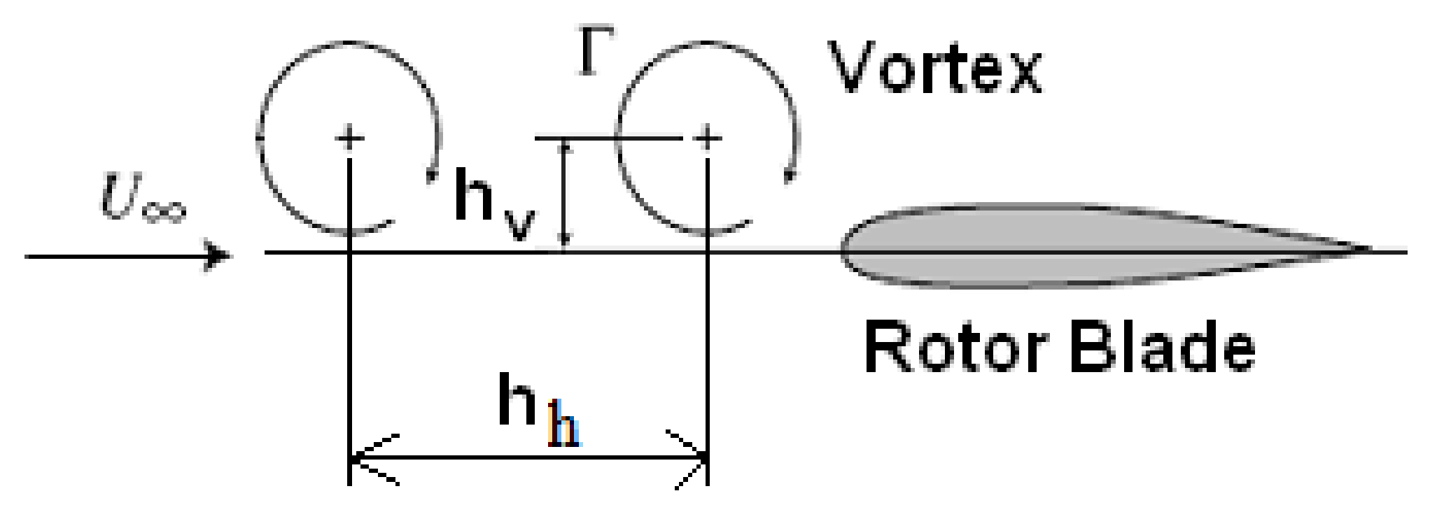
Figure 1 presents a schematic of the blade–vortex-street interactions. This study focuses on the influence of rotor–vortex-street interactions on quadrotor unmanned arial vehicle (UAV) aerodynamics. In particular, the merging of two successive vortices is expected to have a pronounced effect on the local flow field and the aerodynamic performance of the quadrotor UAV. This vortex-merging process will be analyzed and presented in detail. The most critical flight conditions, where vortex merging plays a significant role, occur when the horizontal offset distance, h h , is equal to or smaller than the airfoil chord length, c. For larger horizontal offset distances, vortex merging is negligible, reducing the interaction to a single vortex–airfoil case. Accordingly, the present study examines three critical offset distances: h h = 1 c / 3 , h h = 2 c / 3 and h h = 3 c / 3 . Prior research has demonstrated that the fixed-blade assumption yields valid results [1,2,10,12,14,16,35]; therefore, this study adopts a fixed-blade configuration. Computational simulations are conducted at a Reynolds number Re = 1.3 × 10⁶, based on the free-stream velocity, U ∞ , and the airfoil chord length, c.
The simulations were performed sequentially to ensure physically consistent initial conditions. First, a steady-state RANS simulation using the SST turbulence model was conducted for uniform flow past an NACA0012 airfoil. The converged RANS solution was then used to initialize an LES of uniform flow. Finally, the converged LES fields of pressure and velocity were employed to initialize the LES with superimposed vortex streets. This strategy ensured that all simulations started from fully developed and converged flow fields.

2.2.2. Computational Domain

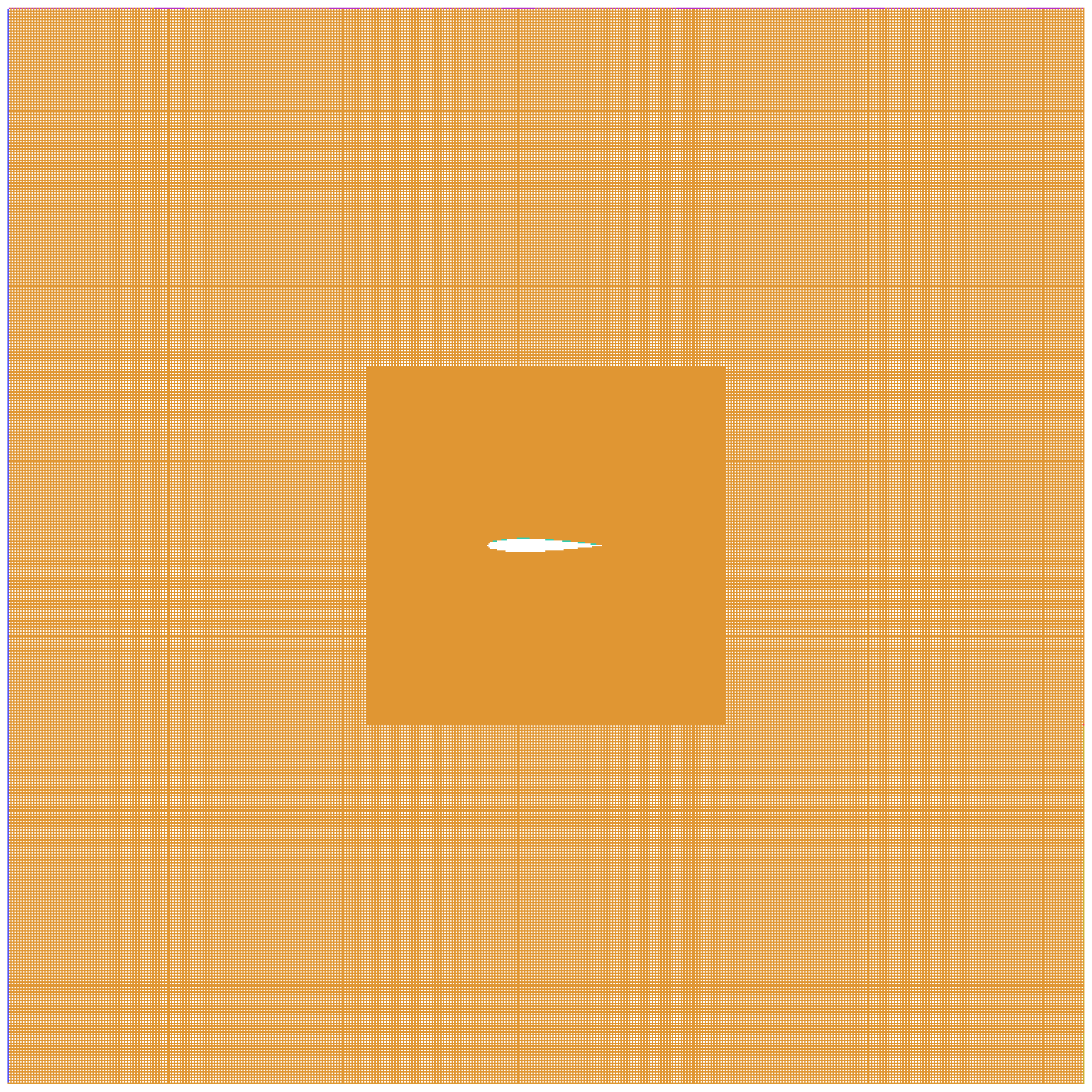
The computational domain is illustrated in Figure 2. The simulations are conducted using an NACA0012 airfoil with a chord length of c = 0.2 m. The computational domain is a square with a side length of 9 c and a span of 1.5 c.
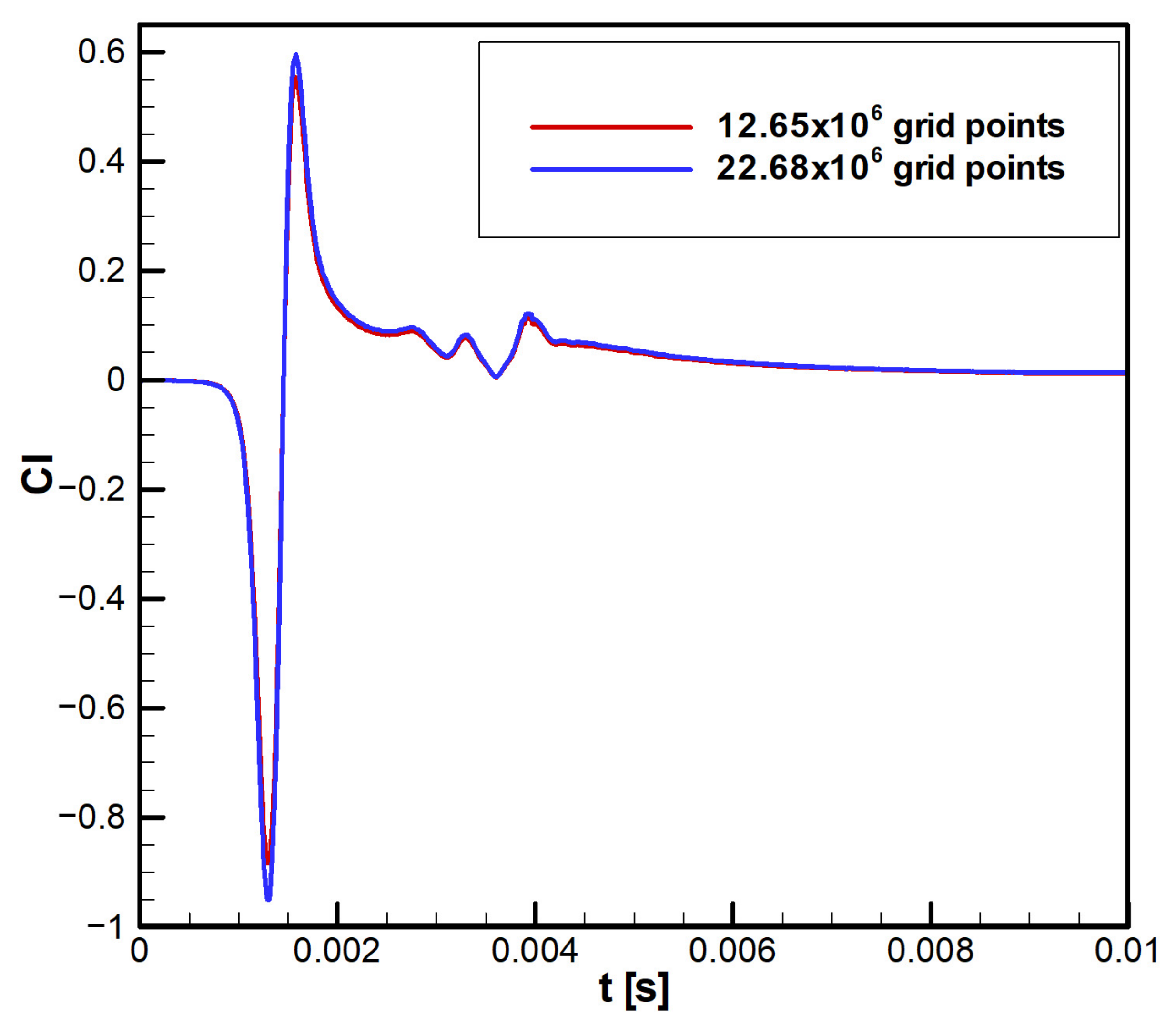
The computational grid was designed to adequately resolve the large-scale turbulent structures governing vortex–airfoil interactions. A grid independence study was conducted using progressively refined meshes, and negligible variation (<1%) in the mean lift coefficient and pressure distribution was observed beyond the selected grid. To ensure adequate wall resolution for the LES, the non-dimensional wall distance y+ of the first cell adjacent to the airfoil surface was estimated. The friction velocity was calculated based on Equation (15):
u τ = τ w ρ
The wall shear stress value τ w = 17   P a was calculated from the LES computations of uniform flow past an NACA0012 airfoil at A o A = 0 ° . For air density ρ = 1.225   k g m 3 , the resulting value of the friction velocity u τ = 3.725   m / s was found. The non-dimensional wall distance was calculated based on Equation (16):
y + = y 1 u τ ν
where y 1 is the first grid point from the airfoil surface. For all the current simulations, the first grid point is located at 3.5 × 10⁻⁶ m. Thus, y+ = 0.84. This y+ value is within the recommended range for a wall-resolved LES y + ≤ 1 , ensuring that near-wall velocity gradients are properly captured. It is worth noting here that a mesh geometric expansion was applied as well, following the algorithm given by Equation (17):
∆ y n = ∆ y 1 · r n − 1
where ∆ y 1 is the first cell height, r = 1.05 is the geometric expansion factor (growth ratio), n is the cell index, and ∆ y n is the size of the nth cell. Grid independence studies were conducted by progressively refining the mesh near the wall until changes in lift, drag, and near-wall pressure distributions were below 1%.
The use of a quasi-three-dimensional computational domain introduces inherent limitations in the prediction of aerodynamic quantities, particularly for flows that are intrinsically three-dimensional. In a 2D framework, spanwise flow variations, vortex stretching, and three-dimensional instabilities are not resolved. As a result, vortical structures tend to remain more coherent and persistent compared to real flows, where energy is redistributed across three-dimensional turbulence scales. This can lead to the overprediction of vortex strength and the associated amplification of unsteady aerodynamic loads. Furthermore, the absence of spanwise turbulence transport in 2D simulations reduces the natural dissipation mechanisms present in three-dimensional flows, potentially affecting the accuracy of velocity and pressure fields. Consequently, quantities such as lift and pressure fluctuations may exhibit higher amplitudes and reduced damping compared to realistic configurations. Despite these limitations, the quasi-three-dimensional approach remains valuable for isolating the fundamental physics of vortex–airfoil interactions, as it allows for high spatial and temporal resolution at a significantly reduced computational cost [41,42,43,44]. Therefore, the present study employs a quasi-three-dimensional model to capture the primary interaction mechanisms, while acknowledging that quantitative differences may exist compared to fully three-dimensional simulations.

2.2.3. Boundary Conditions and Initial Conditions

A uniform inflow of speed U ∞ = 100   m / s is applied at the inlet, determined based on the blade tip velocity [40]. A Rankine vortex is superimposed on the uniform flow at an upstream location, chosen to avoid any initialization effects on the blade–vortex interaction (BVI) phenomenon. Dirichlet boundary conditions are imposed on the airfoil surface, free-slip conditions are applied at the top and bottom walls, and symmetry conditions are applied on the side walls of the domain.
The flow velocity of U = 100 m/s was selected to represent realistic rotor blade tip speeds while maintaining computational feasibility. This value lies within the range of tip velocities reported in historical and recent experimental and computational studies of rotorcraft in hover and low-speed forward flight [51,53,54,55,56], capturing the key aerodynamic phenomena associated with blade–vortex interactions (BVIs). Early wind-tunnel experiments employed higher tip speeds around 152 m/s [51,53,54], whereas later scaled rotor tests report tip velocities between 55 and 103 m/s [55,56]. More recent high-fidelity numerical and experimental investigations have explored even higher tip speeds, up to 242 m/s [57,58,59], for detailed BVI characterization.
The chosen speed of 100 m/s ensures the flow remains fully turbulent and adequately represents unsteady BVI effects, including vortex shedding, fine-scale vorticity redistribution, and fluctuations in lift and drag, while keeping computational costs manageable. This compromise provides a realistic yet tractable framework for studying canonical rotor–vortex interactions relevant to UAV and multirotor systems.

2.2.4. Numerical Schemes

Time integration is performed using a fourth-order Runge–Kutta scheme, while spatial discretization employs a second-order scheme. A fixed time step ∆ t = 8.5 × 10 − 8   s is used for all LESs. Computations are carried out on a high-performance computing system using the Message Passing Interface (MPI) for parallelization.
Key LES quality indicators were monitored to ensure the reliability of the results. The near-wall resolution was maintained with y+ < 1, the maximum Courant–Friedrichs–Lewy (CFL) number remained below 1, and a time-step independence study confirmed temporal convergence of the aerodynamic coefficients. Together, these measures validate that the LES accurately resolves the unsteady flow structures relevant to vortex–airfoil interactions.
Time-step selection was guided by the Courant–Friedrichs–Lewy (CFL) condition to ensure numerical stability and temporal resolution of unsteady vortex dynamics. The CFL number is given by Equation (18):
C F L = U m a x ∆ t ∆ x m i n
where U m a x is the local flow velocity, ∆ t is the time step, and ∆ x m i n is the smallest grid spacing near the airfoil. For the present simulations, the minimum cell size adjacent to the wall is ∆ x m i n = 1 × 10 − 5   m . For freestream velocity U m a x = 100   m / s , a time step ∆ t = 8.5 × 10 − 8   s was chosen, which yielded a maximum CFL number C F L m a x = 0.85 , which was less than 1. Temporal convergence was verified by reducing the time step by factors of 2 and 4, observing less than 1% variation in lift, drag, and pressure fluctuations on the airfoil. These tests confirm that the selected time step resolves the unsteady aerodynamic features, including vortex shedding and blade–vortex interactions, without introducing numerical artifacts.
A time-step convergence study was conducted to ensure that the numerical results are independent of the selected time step. Simulations were performed for Δt = 1.275 × 10⁻⁷ s, Δt = 8.5 × 10⁻⁸ s, and Δt = 4.25 × 10⁻⁸ s, at a freestream velocity of U = 100 m/s and a chord length of c = 0.2 m. Key aerodynamic quantities, including the instantaneous lift and drag coefficients as well as the local pressure fluctuations, were monitored. The differences between the results obtained with Δt = 8.5 × 10⁻⁸ s and Δt = 4.25 × 10⁻⁸ s were found to be less than 1%, indicating that the solution has reached time-step independence. Based on this study, Δt = 8.5 × 10⁻⁸ s was adopted for all subsequent LESs, providing a balance between numerical accuracy and computational efficiency.

2.2.5. Grid Size and Grid Convergence

As already mentioned, Figure 2 shows the grid distribution within the computational domain. To accurately capture near-field flow physics, mesh refinement is applied near the airfoil. Grid independence is demonstrated in Figure 3, confirming that the simulations resolve the essential flow features. For computational efficiency and MPI implementation, the domain is divided into 12 multi-block regions, and a mesh of 12.6 × 10 6 grid points was chosen.
The subgrid-scale (SGS) sensitivity analysis is beyond the scope of the present study. Therefore, the dynamic Smagorinsky model was adopted based on extensive prior investigations of SGS modeling in the large-eddy simulation (LES) [57,58,59,60,61]. These studies demonstrate that the dynamic Smagorinsky model is generally preferred over the constant-coefficient Smagorinsky–Lilly model, as it evaluates the model coefficient locally using the resolved flow field rather than prescribing a fixed global value. In the standard Smagorinsky–Lilly model, the constant coefficient does not vary in space or time, which can lead to excessive numerical dissipation, particularly in regions of strong shear and near-wall flows. This limitation may result in the attenuation of vortical structures and the underprediction of unsteady aerodynamic loads. In contrast, the dynamic Smagorinsky model employs a test-filtering procedure to determine the model coefficient adaptively based on the local turbulence characteristics. This approach reduces artificial dissipation and improves the representation of both large-scale coherent vortices and smaller turbulent fluctuations.

2.2.6. Data Validation

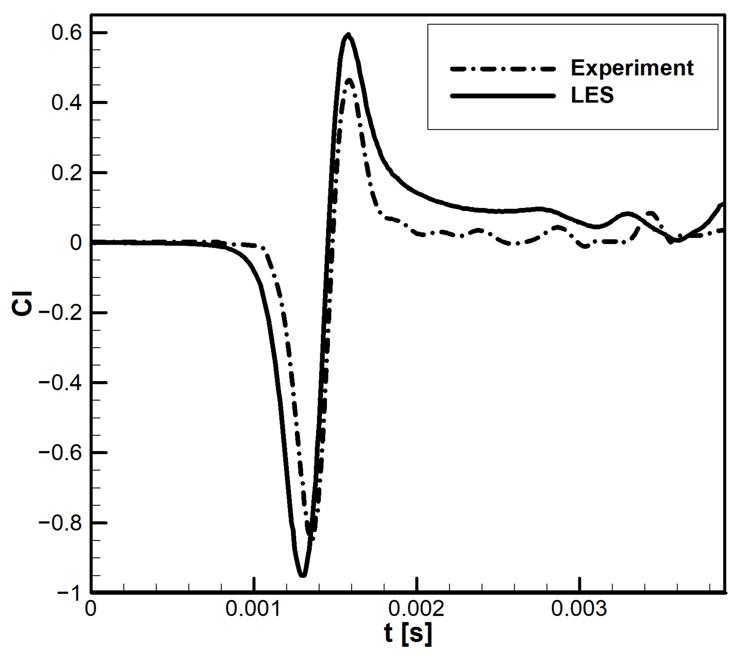
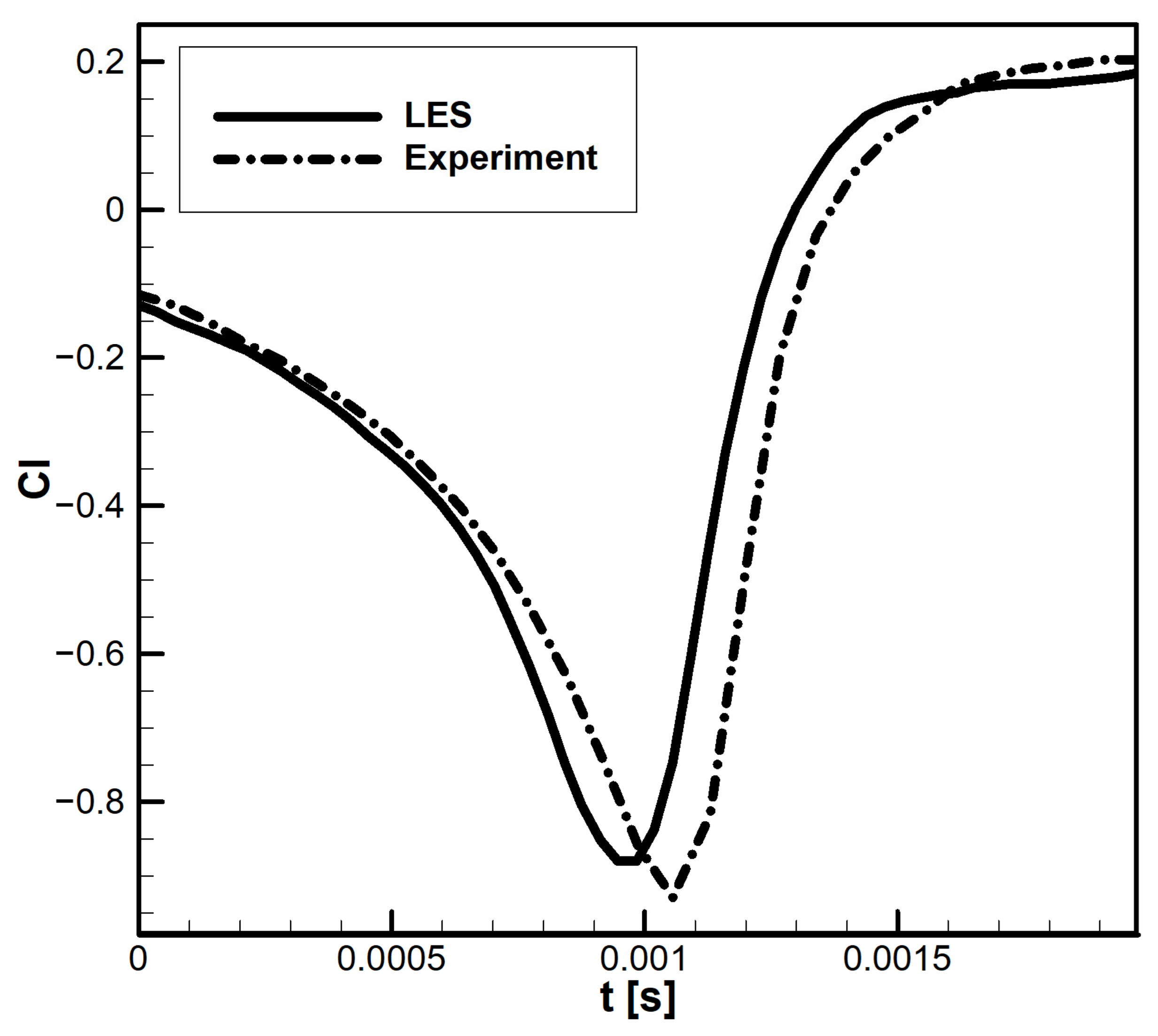
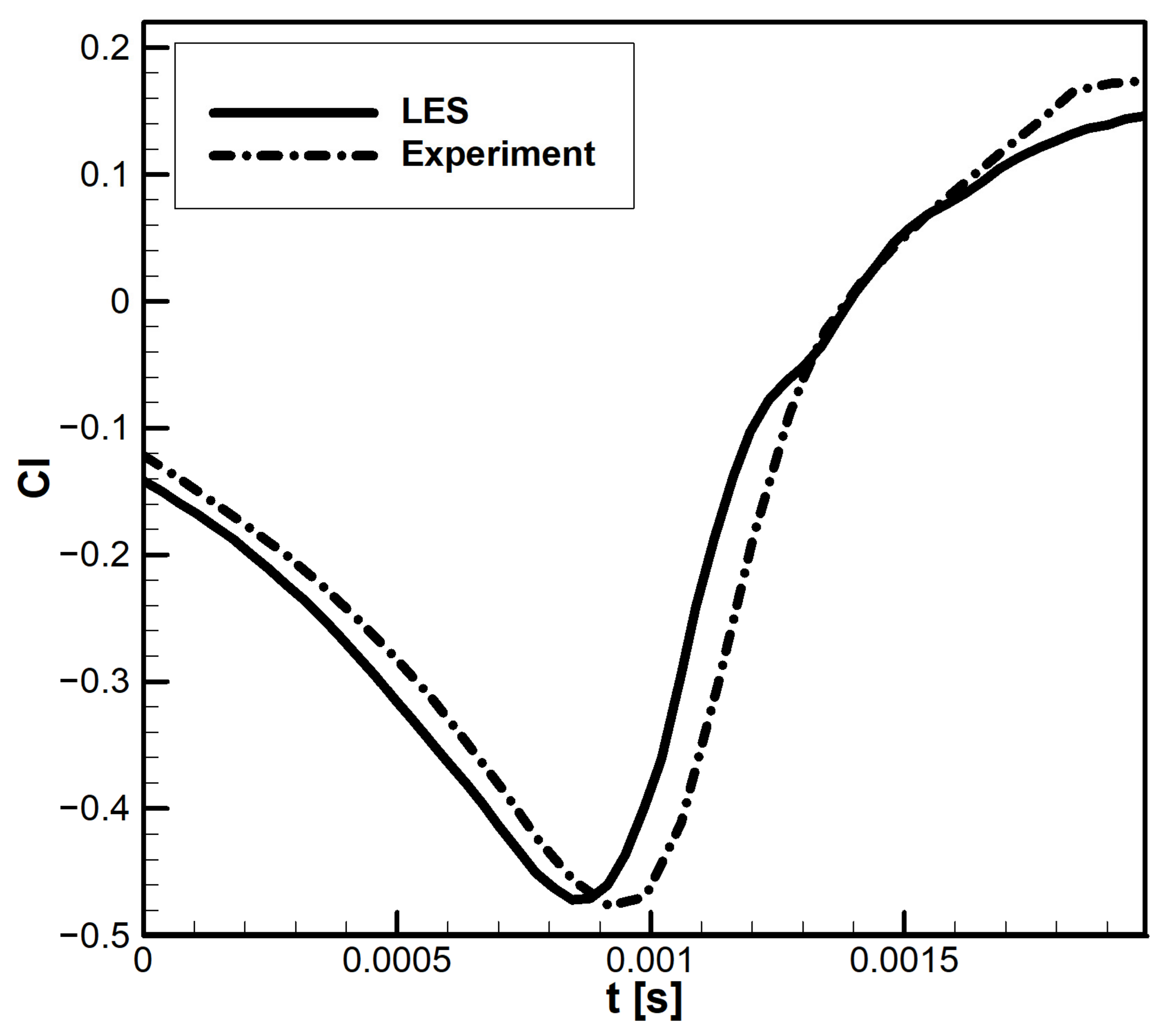
The computational results were validated against experimental data [15]. Comparisons show good agreement, with minor differences attributed to vortex dissipation in the experiments, as shown in Figure 4. The differences between LES predictions and experimental lift and drag coefficient measurements in blade–vortex street interactions are primarily attributed to slight phase discrepancies in vortex convection. Additionally, small timing shifts in vortex–blade encounters can alter the amplitude and spectral content of the unsteady loads.
Further validation was performed using independent datasets [17], as shown in Figure 5 and Figure 6. The results again demonstrate good agreement, with discrepancies arising from uncertainties in the vortex release location. Comparisons were conducted for two BVI scenarios, differentiated by blade–vortex vertical offset distance ( h v ) , referred to as strong and weak BVIs, respectively.
As already mentioned above, the discrepancies between LES predictions and experimental lift and drag measurements in blade–vortex street interactions are primarily attributed to slight phase discrepancies in vortex convection and small timing shifts in vortex–blade encounters, which alter the amplitude and spectral content of the unsteady loads.
In the present study, lift coefficient comparisons are provided as a primary quantitative metric to assess the overall aerodynamic response and to demonstrate agreement with classical blade–vortex interaction (BVI) behavior. A quantitative comparison between LES and experimental lift coefficient histories indicates good agreement in capturing the primary unsteady features, including the sharp negative peak and subsequent recovery. An approximate RMS-based comparison of the normalized signals shows a relative discrepancy of the order of 7–9% of the peak lift amplitude. These differences are primarily attributed to two factors: (i) the natural dissipation of vortices within the wind tunnel setup and (ii) the inherently two-dimensional (2D) nature of the computational domain, which can cause slight phase lag and peak amplitude overprediction in the LES results.
The use of a quasi-three-dimensional computational domain introduces inherent limitations in the prediction of aerodynamic quantities, particularly for flows that are intrinsically three-dimensional. In a quasi-three-dimensional framework, spanwise flow variations, vortex stretching, and three-dimensional instabilities are not resolved. As a result, vortical structures tend to remain more coherent and persistent compared to real flows, where energy is redistributed across three-dimensional turbulence scales. This can lead to an overprediction of vortex strength and an associated amplification of unsteady aerodynamic loads. Furthermore, the absence of spanwise turbulence transport in quasi-three-dimensional simulations reduces the natural dissipation mechanisms present in three-dimensional flows, potentially affecting the accuracy of velocity and pressure fields. Consequently, quantities such as lift and pressure fluctuations may exhibit higher amplitudes and reduced damping compared to realistic configurations. Despite these limitations, the quasi-three-dimensional approach remains valuable for isolating the fundamental physics of vortex–airfoil interactions, as it allows for high spatial and temporal resolution at a significantly reduced computational cost [43,44,46,47,50,51,53]. Previous studies have shown that the aspect ratio has a minimal influence on mean aerodynamic characteristics, including lift and drag coefficients, as well as the mean locations of flow separation and reattachment [40,41,47,48,57]. Therefore, the present study employs a quasi-three-dimensional model to capture the primary interaction mechanisms, while acknowledging that quantitative differences may exist compared to fully three-dimensional simulations. Future work could extend the analysis to include quantitative phase comparisons, frequency-domain characterization, and fully three-dimensional rotor simulations to achieve more comprehensive validation and better assess unsteady aerodynamic loads relevant to rotorcraft noise, vibration, and structural effects.
Spectral comparisons can provide additional quantitative insights into the model’s capability to resolve unsteady flow dynamics and the associated turbulent energy distribution. In the present study, the primary focus is placed on capturing the dominant physical mechanisms governing vortex–airfoil interactions and the resulting unsteady aerodynamic loads. The numerical results successfully reproduce key flow features, including vortex merging, induced velocity amplification, and pressure fluctuations, which are consistent with well-established blade–vortex interaction (BVI) behavior reported in the literature [40,43,44,47,50,51,53,60].
Although a detailed frequency-domain analysis is not included, the agreement of these fundamental flow characteristics with prior studies supports the ability of the model to capture the essential unsteady physics. The inclusion of spectral analysis, such as power spectral density and dominant frequency content, would further enhance the quantitative validation of the simulations. This aspect will be addressed in future work through direct comparisons with experimental measurements or high-fidelity numerical data, enabling a more comprehensive assessment of model accuracy across temporal scales.

3. Results

The results are presented in two main sections. The first section focuses on the flow physics associated with rotor–vortex interactions in a quadcopter UAV, examining the effects of blade–vortex interaction (BVI) on the local velocity and pressure fields around the rotating blades. Special attention is given to the unsteady aerodynamic loads generated as tip vortices shed from one rotor interact with subsequent blades or neighboring rotors. The second section investigates rotor–wake and rotor–vortex-street interactions within the quadcopter configuration, highlighting how the aerodynamic performance metric, such as lift and drag coefficients, vary with horizontal and vertical rotor spacing. This analysis clarifies the influence of wake interference and vortex convection on overall aerodynamic efficiency and unmanned aerial vehicle stability.

3.1. Airfoil–Vortex-Street Interactions

As introduced, the first part of this study investigates rotor–vortex-street interactions in a quadcopter UAV configuration. A review of the existing literature reveals that multirotor wake–interference mechanisms under these specific conditions remain insufficiently characterized, particularly in comparison to isolated blade–vortex interaction (BVI) scenarios [1,2,6,16,24,25,26,27,28,35,37,39,40,47,60]. The central hypothesis of this work is that the horizontal offset distance h h between consecutively shed vortices constitutes the primary governing parameter controlling the interaction regime in rotor–vortex-street configurations. Specifically, when the offset distance becomes comparable to or smaller than the blade chord length, the interaction mechanism transitions from weak convective interference to strong, nonlinear coupling between the rotor blades and the incoming vortex street. This regime is expected to amplify unsteady pressure fluctuations, modify local inflow angles, and significantly alter aerodynamic loading compared with single blade–vortex encounters. To evaluate this hypothesis, the section first presents the detailed flow-field characteristics, including velocity and pressure distributions within the interacting rotor wakes. Subsequently, the impact of these wake interactions on quadcopter aerodynamic performance, quantified through lift and drag coefficients, is examined. For clarity and systematic interpretation, the analysis is structured according to varying horizontal offset distances ( h h ) , enabling the isolation of the critical spacing thresholds that define distinct aerodynamic interaction regimes.

3.1.1. Analysis of the Velocity Field

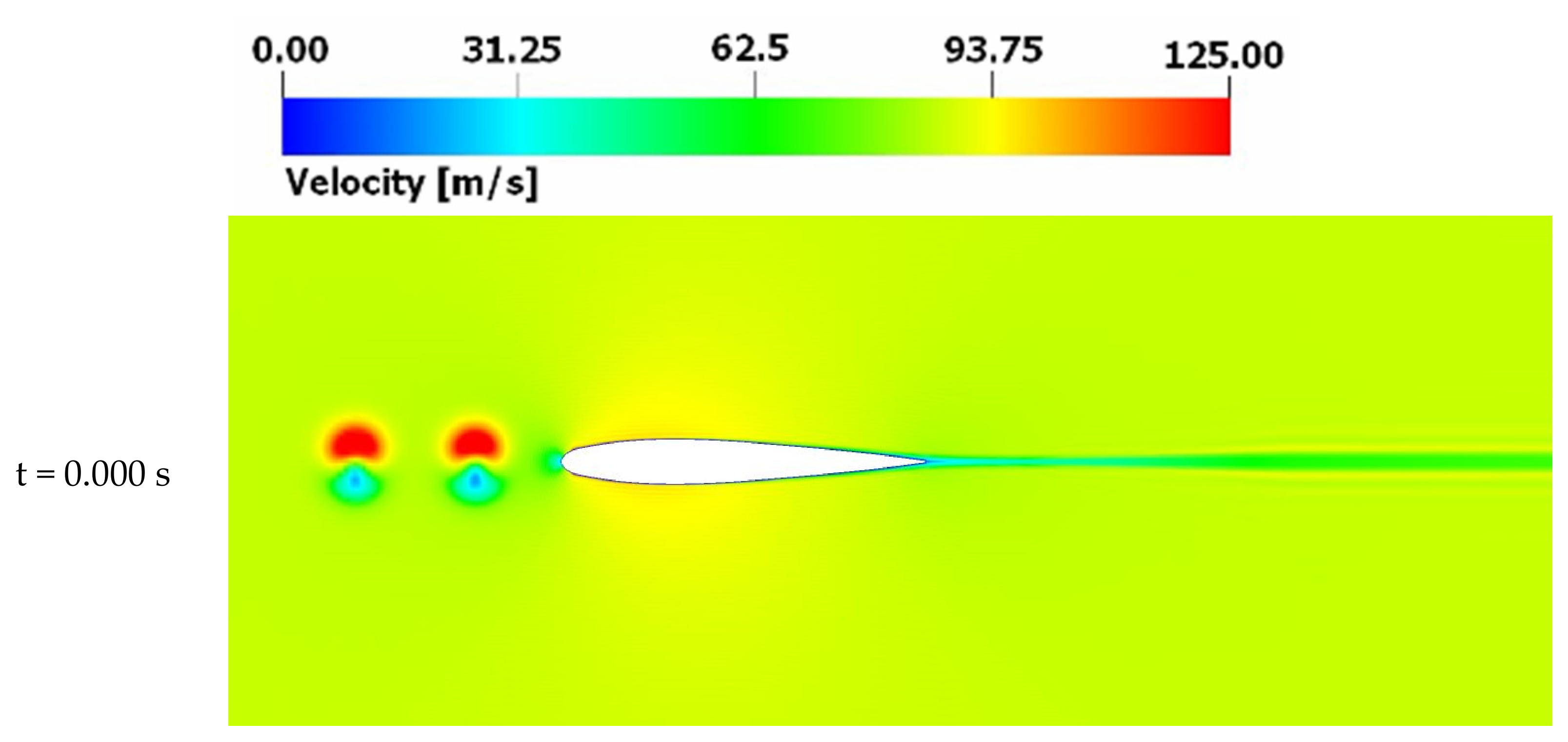
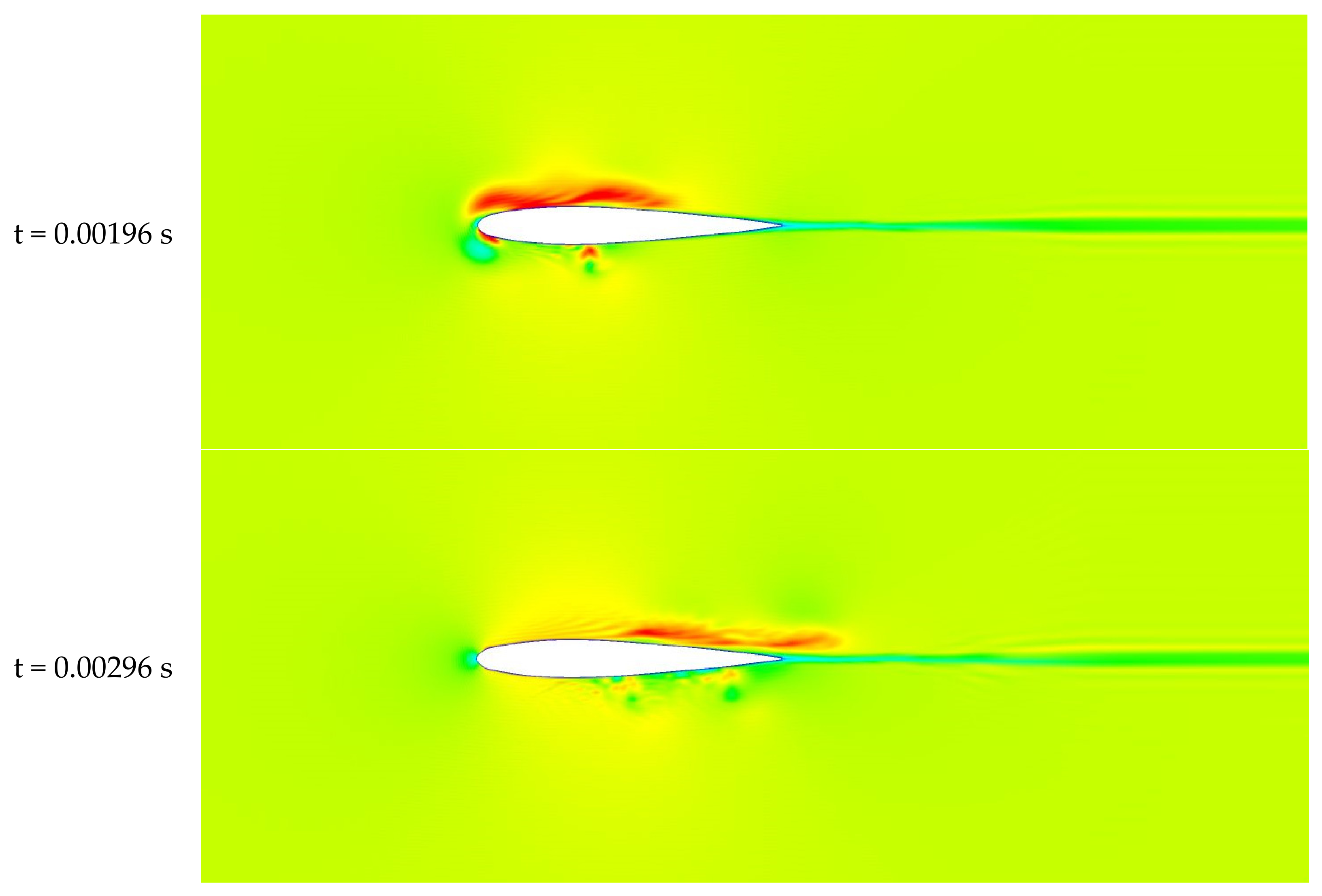
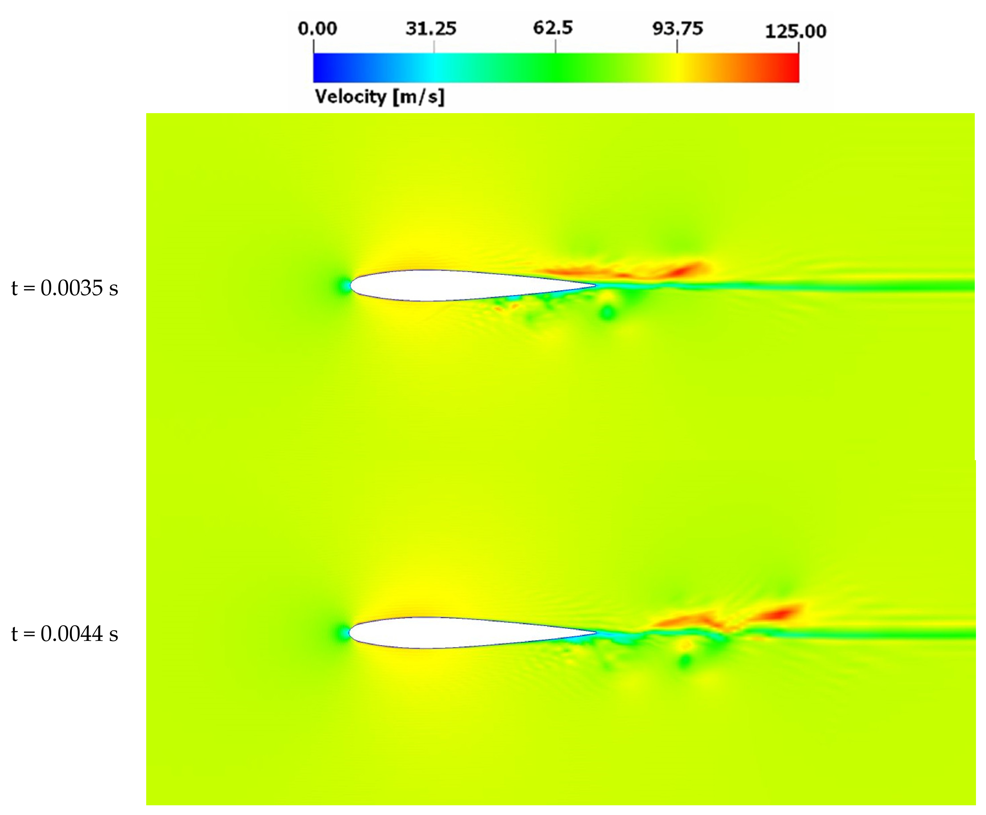
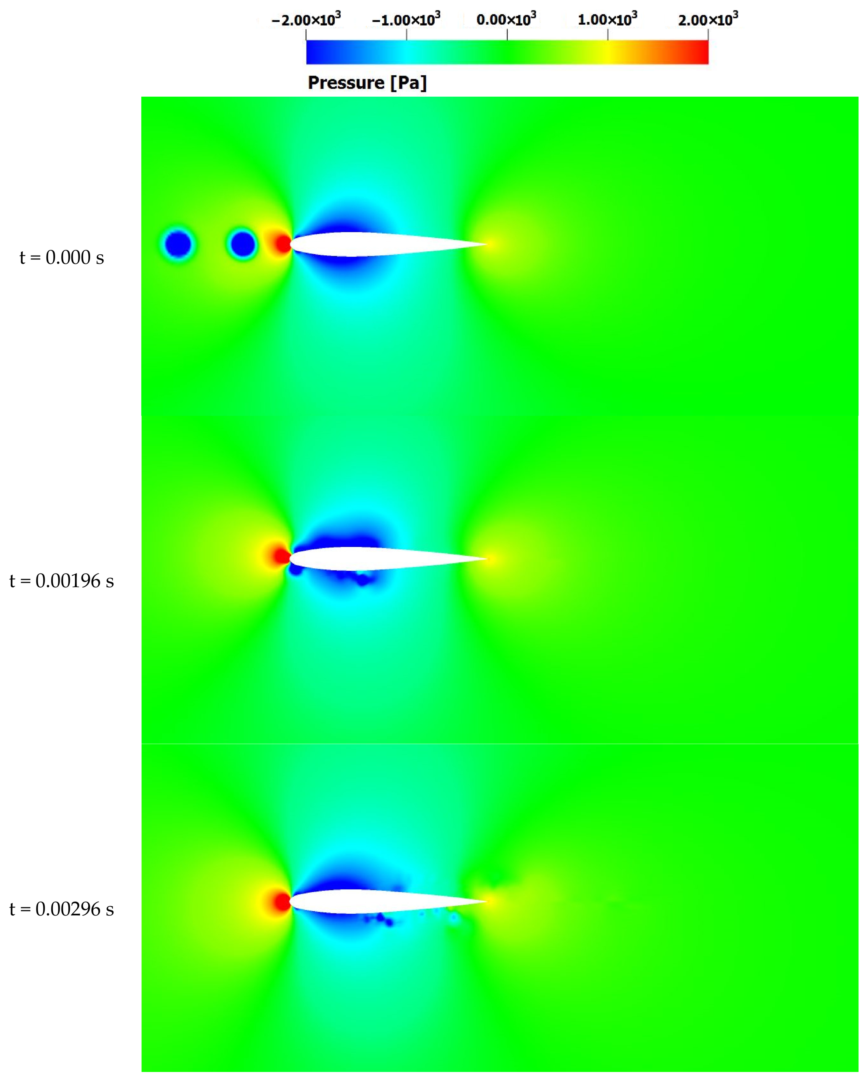
Figure 7 presents instantaneous velocity magnitude contours for rotor–vortex-street interactions at a prescribed horizontal vortex offset distance ( h h = 1 3 c ) . At t = 0.00 s, the computational domain is initialized with two coherent tip-vortex structures positioned upstream of the rotor disk, representing an undisturbed inflow prior to blade–wake coupling. The velocity field at this stage exhibits symmetric induced flow with no significant distortion of the rotor loading distribution. At t = 0.00196 s, the convecting vortices enter the rotor disk and begin interacting with the rotating blade. The interaction is characterized by strong vortex stretching and partial merging with the blade-generated tip vortices. Compared with isolated blade–vortex interaction cases, the blade–vortex-street interaction configuration exhibits a substantially expanded region of elevated velocity magnitude on the suction side of the blade. This amplification results from constructive superposition of induced velocity components and vortex core deformation. The localized increase in velocity gradients near the blade leading-edge produces intensified pressure deficits, as evidenced by concentrated low-pressure regions in the instantaneous pressure field (Figure 3). Additionally, the azimuthal phase at which vortex impingement occurs modulates the strength of the induced inflow, leading to pronounced unsteady aerodynamic loading. The extent of vortex merging and induced velocity amplification is strongly dependent on the horizontal offset distance ( h h ) , which governs the degree of wake coherence and interaction strength within the blade wake system. These results demonstrate that the rotor–vortex-street coupling in multirotor configurations generates nonlinear wake interference effects that differ fundamentally from classical single-rotor blade–vortex interaction mechanisms.
A residual vortical structure is observed beneath the rotor blade at t = 0.00196 s, corresponding to the initial stage of vortex–blade impingement. As the convecting vortices travel along the blade chord, this remnant vortex undergoes progressive deformation and attenuation due to vortex merging and stretching induced by the rotating blade. The merging process redistributes vorticity into the rotor wake, accelerating dissipation of the coherent residual structure, as seen at t = 0.00296 s.
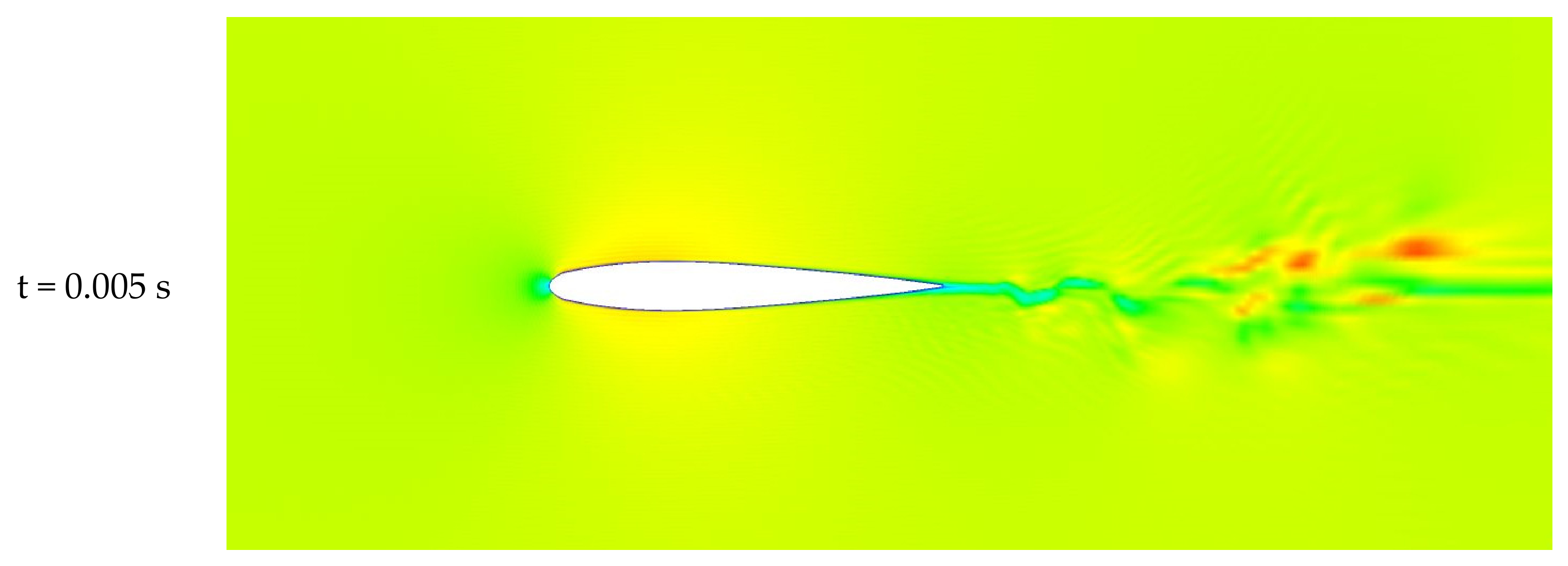
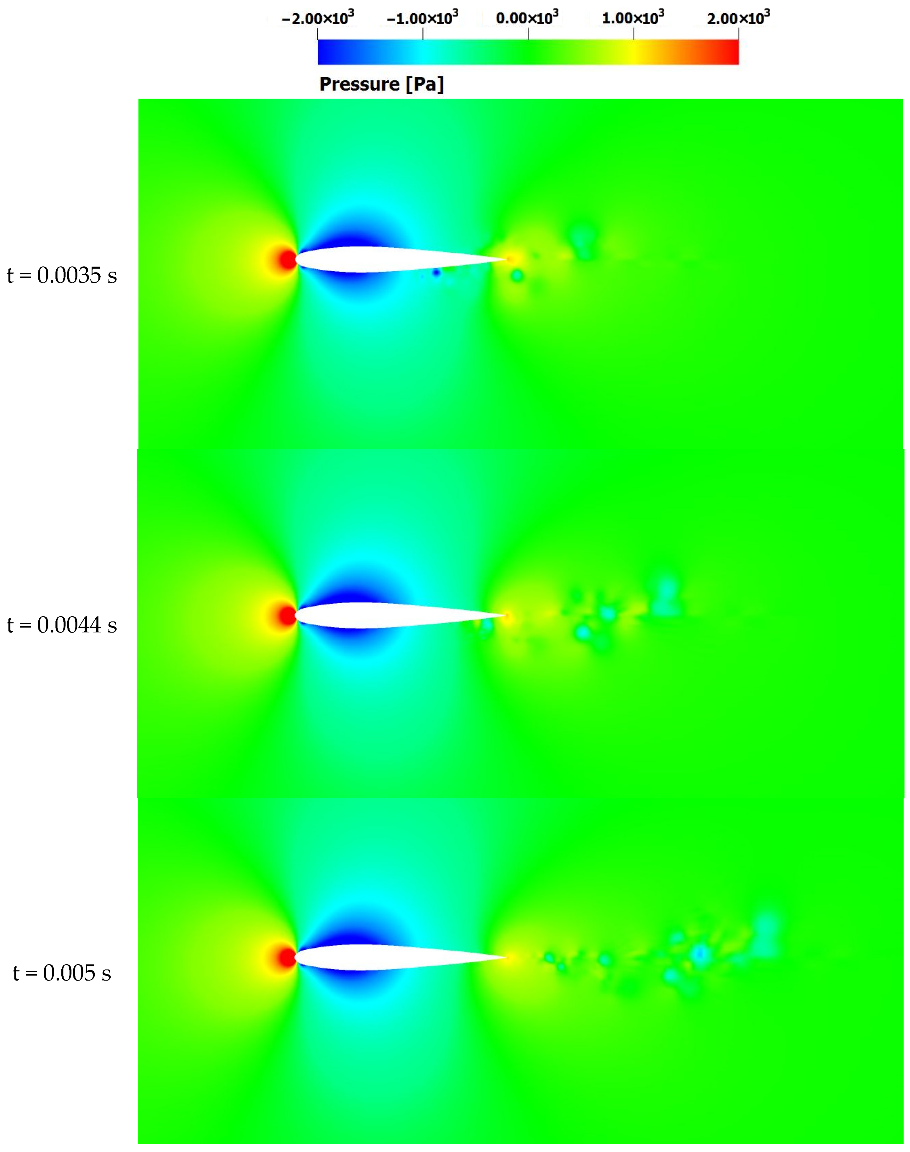
As illustrated in Figure 8, continued vortex merging causes the residual vortex components to rapidly convect downstream into the rotor slipstream. This redistribution of vorticity enhances wake turbulence intensity and modifies the induced velocity field. The interaction process also generates significant unsteady aerodynamic loading on the blade, evidenced by pronounced flow-field fluctuations at t = 0.005 s.
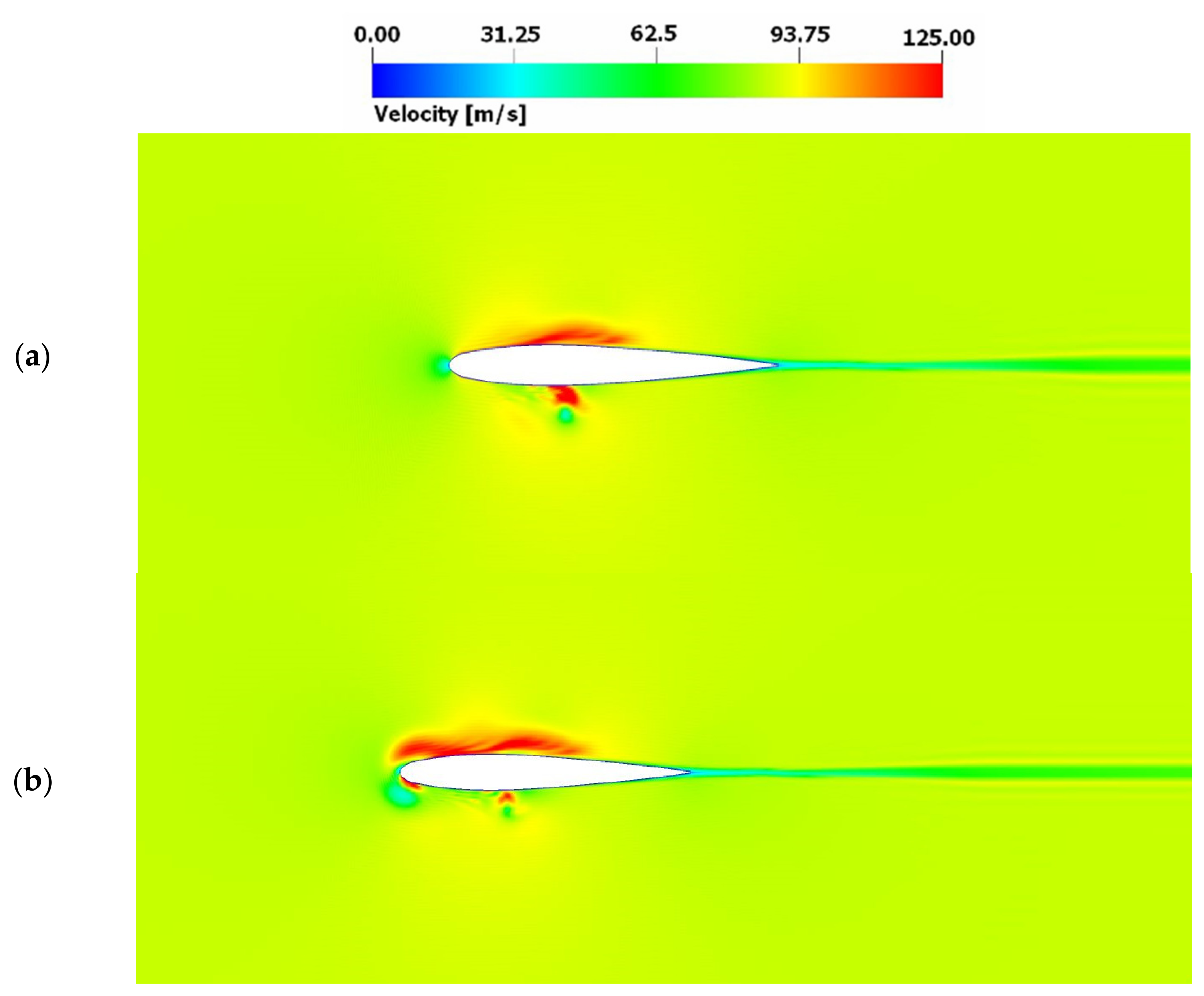
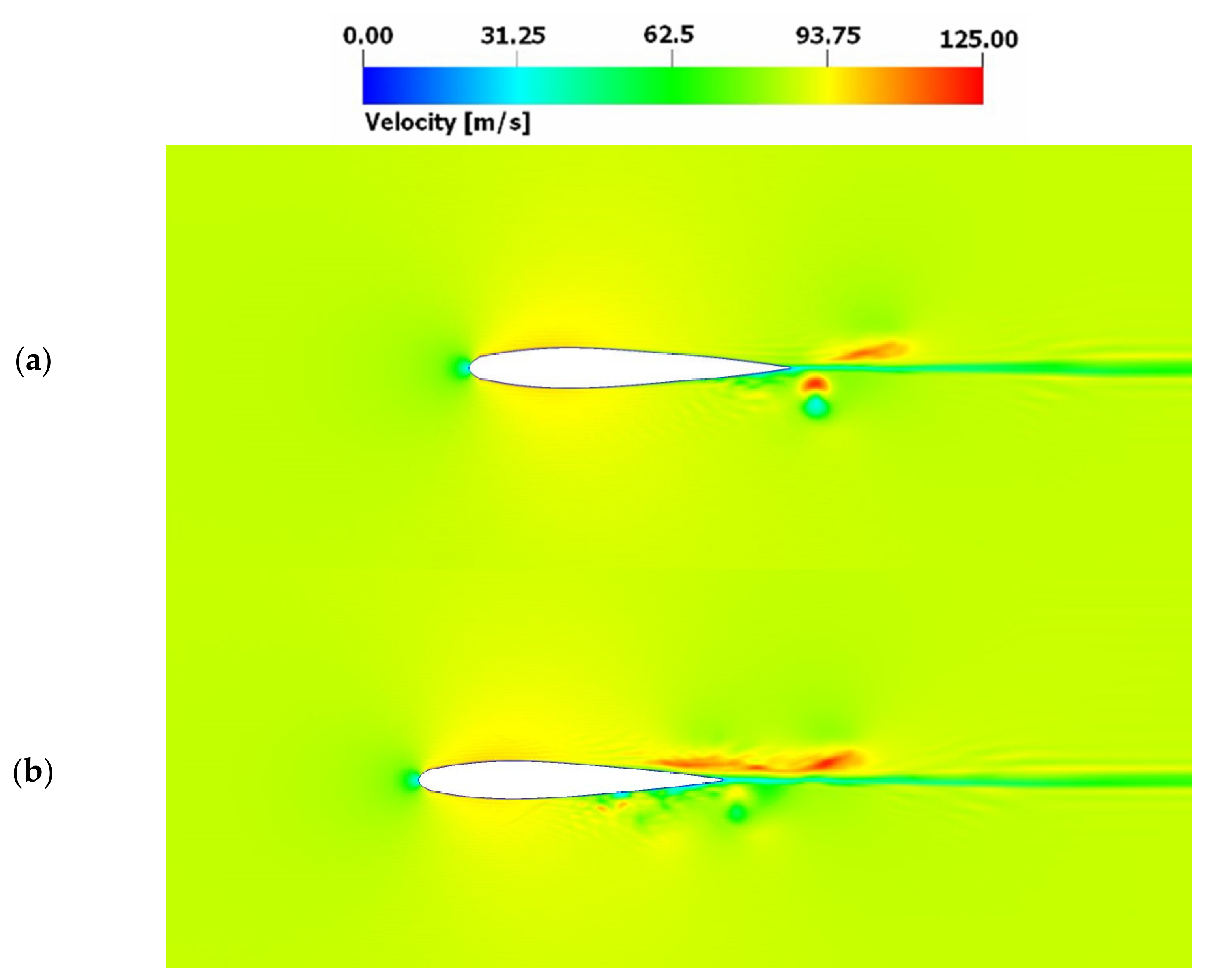
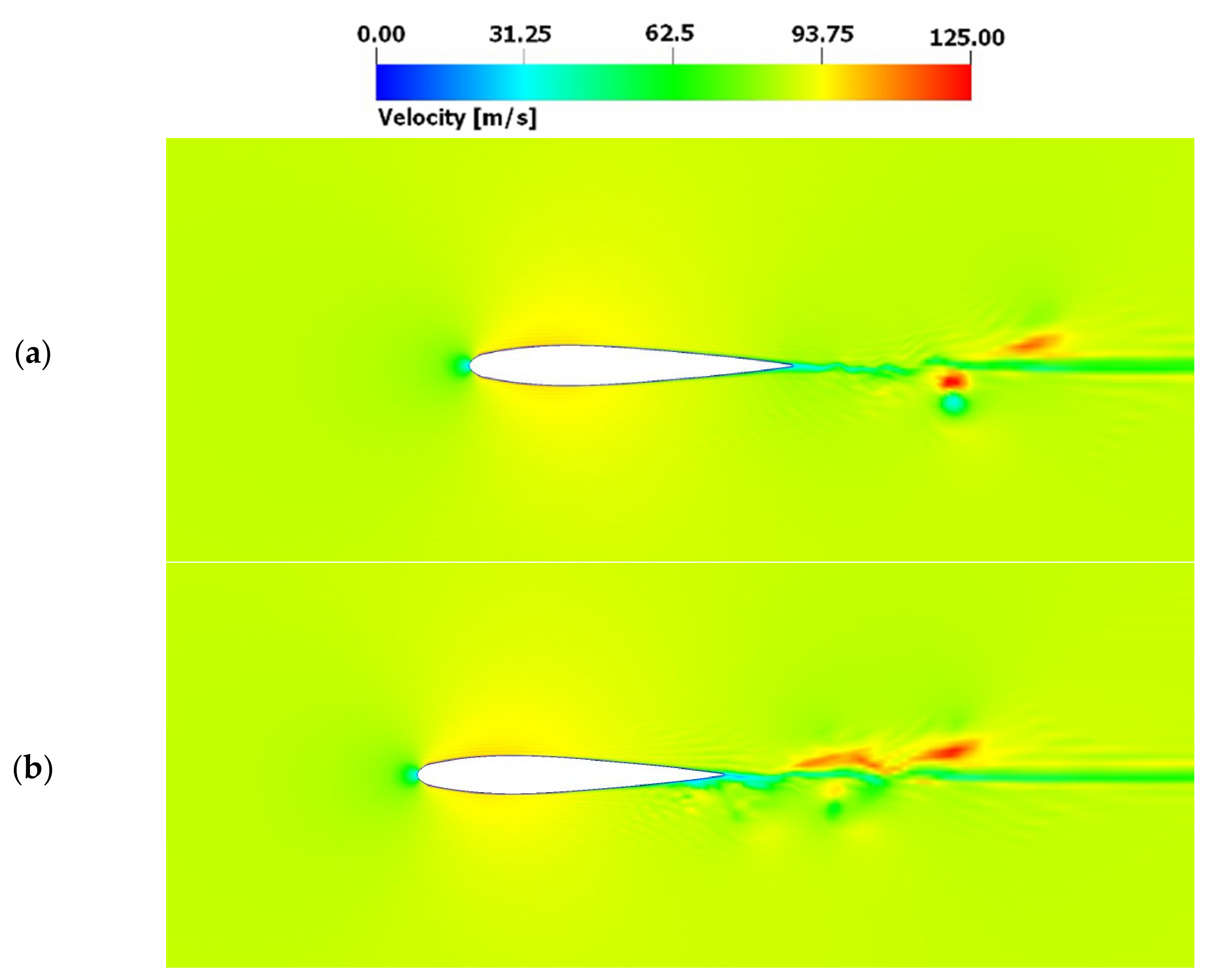
Figure 9 compares instantaneous velocity fields for isolated rotor–vortex interaction and rotor–vortex-street interaction cases. In the vortex-street configuration, the merging phenomenon extends over a larger portion of the blade chord, producing a broader region of elevated velocity magnitude on the suction side. This indicates the stronger constructive superposition of induced velocities. Conversely, the residual vortex beneath the blade is weaker than in the isolated vortex case, reflecting more rapid vorticity redistribution.
Figure 10 further demonstrates that, in single-vortex interactions, the residual vortex dissipates gradually, maintaining coherence over a longer convection distance. In contrast, vortex-street interactions promote a faster breakdown of the remnant structure due to multi-vortex coupling effects. As a result, the downstream rotor wake exhibits increased strength and complexity in the vortex-street case, as shown in Figure 11. This intensified wake structure has direct implications for inter-rotor interference and overall quadrotor aerodynamic efficiency.

3.1.2. Analysis of the Pressure Field

The observed modifications in the velocity field directly translate into corresponding variations in the instantaneous pressure distribution over the rotor blade. As shown in Figure 12, at t = 0.00196 s, rotor–vortex-street interactions generate pronounced pressure disturbances within the near-field of the rotor disk. The merging vortices intensify the induced velocity on the suction side of the blade, producing concentrated low-pressure cores and steep pressure gradients near the leading-edge. These gradients are responsible for amplified unsteady aerodynamic loading during the impingement phase. Simultaneously, the pressure field reveals a coupling between the residual vortex beneath the blade and the developing rotor wake.
As vortex merging progresses, momentum exchange between coherent vortex cores enhances turbulent mixing, accelerating the diffusion and scattering of the remnant vortex. This redistribution of vorticity modifies the induced inflow distribution across the rotor disk and contributes to increased wake non-uniformity downstream. The coupled velocity–pressure dynamics therefore demonstrate that vortex-street interactions in quadrotor configurations not only alter instantaneous blade loading but also restructure the slipstream, with implications for lift and drag fluctuations, and overall aerodynamic efficiency.
The results indicate that rotor–vortex-street interactions in the quadrotor UAV configuration predominantly influence the near-field region of the rotor disk, whereas isolated rotor–vortex interactions affect both the near-field and the downstream slipstream development. In the vortex-street case, the interaction is concentrated around the blade–wake coupling zone, leading to localized but intense flow disturbances. Examination of the instantaneous pressure field shows that blade–vortex interactions amplify cyclic disturbances within the surrounding flow. These periodic pressure fluctuations promote the formation of small-scale coherent vortical structures (micro-vortices) near the blade surface and within the inner wake region.
As illustrated in Figure 13 at t = 0.00196 s and t = 0.00296 s, these micro-vortices emerge as a consequence of shear-layer instability triggered by vortex impingement and pressure-gradient amplification. As these small-scale vortical structures convect downstream within the rotor slipstream, they progressively interact and merge with each other and with the primary rotor wake. This multi-scale vortex coupling accelerates vorticity redistribution and promotes the rapid dissipation of coherent structures, as observed at t = 0.005 s. The resulting wake exhibits enhanced mixing and increased turbulence intensity compared with the single-vortex interaction case, highlighting the stronger nonlinear wake dynamics characteristic of blade–vortex-street interactions.
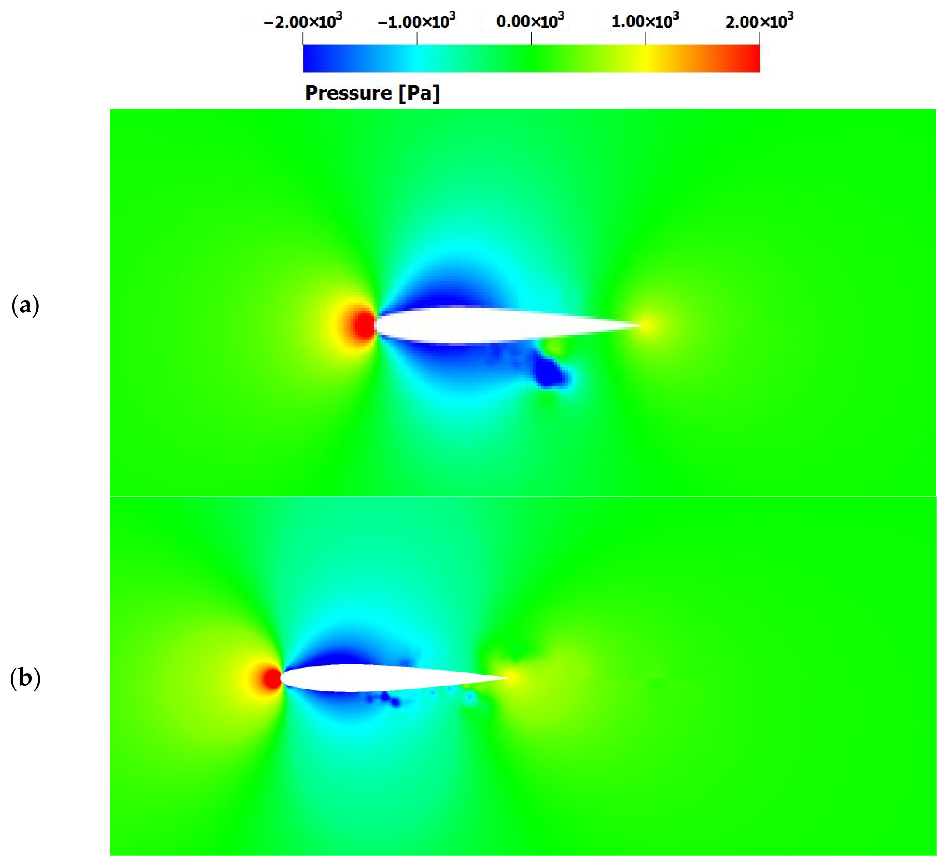
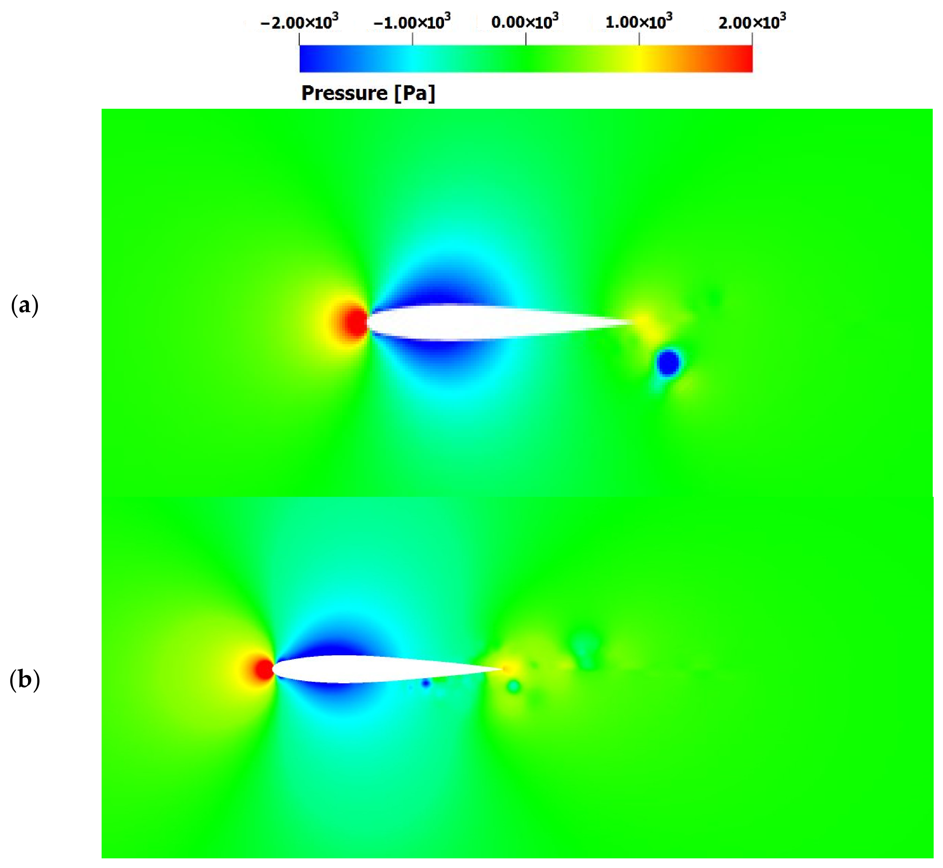
Figure 14 presents a comparison of the instantaneous pressure field for (a) isolated rotor–vortex interactions and (b) rotor–vortex-street interactions at t = 0.00196 s. The comparison indicates that, in the isolated vortex case, the impinging vortex maintains its coherence as it convects toward the rotor blade, resulting in a more concentrated pressure perturbation near the leading-edge. This coherent interaction produces a stronger localized stagnation pressure peak and therefore exerts a more pronounced influence on the instantaneous lift and drag coefficients of the rotor blade. In contrast, under vortex-street interactions, successive vortices undergo partial deformation and mutual interference before reaching the blade. As a result, the induced pressure fluctuations are more distributed and less concentrated than in the single-vortex case. The maximum stagnation pressure in this configuration corresponds to the second vortex impinging on the rotor blade. However, this secondary interaction is weaker than the initial vortex–blade encounter due to prior vortex distortion and energy redistribution within the wake. Consequently, its effect on rotor aerodynamic performance is comparatively reduced. These results suggest that, although vortex-street interactions introduce repeated unsteady loading on the blade, isolated coherent vortex impingement can produce stronger instantaneous aerodynamic coefficient variations.
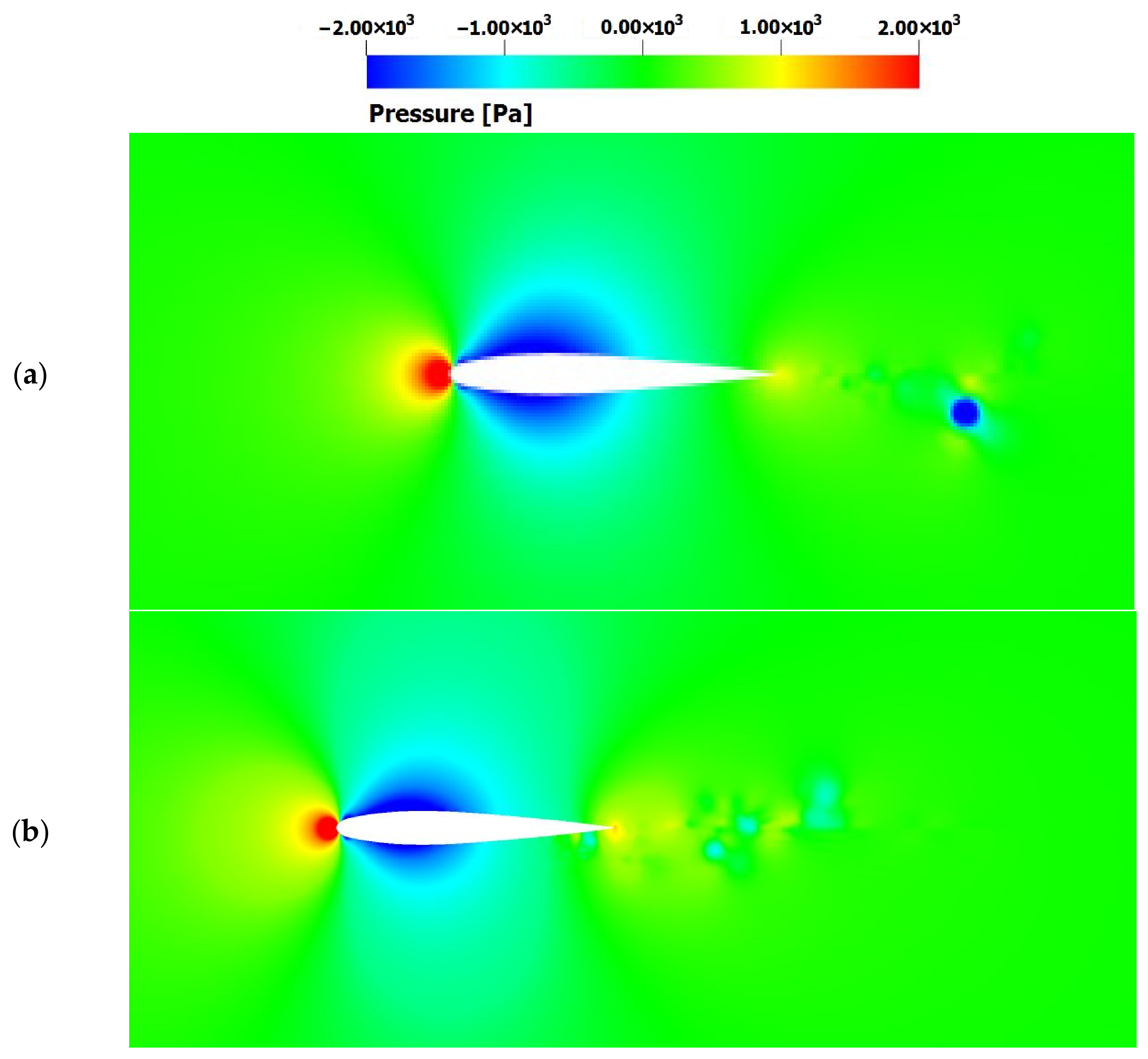
Figure 15 further compares the instantaneous pressure fields for (a) isolated rotor–vortex interactions and (b) rotor–vortex-street interactions at t = 0.0035 s, emphasizing the role of vortex merging in shaping the wake dynamics. In the vortex-street configuration, successive vortices interact with one another prior to blade impingement, leading to partial vortex coalescence and deformation.
This vortex merging accelerates the redistribution of vorticity within the rotor slipstream and promotes the faster attenuation of the remnant coherent structures compared with the isolated vortex case. As also observed in Figure 14, the residual vortex in the vortex-street interaction dissipates more rapidly after blade passage. In contrast, during the isolated rotor–vortex interaction, the coherent vortex core remains more intact, sustaining stronger localized pressure gradients and prolonged wake coherence downstream of the rotor disk. These results indicate that vortex merging in blade–vortex-street interactions significantly alters near-wake structure and unsteady blade loading, thereby affecting lift fluctuations, drag variations, and overall aerodynamic efficiency.
These flow characteristics persist as the residual vortical structures convect further downstream within the blade slipstream. Figure 16 presents a comparison of the instantaneous pressure fields for isolated rotor–vortex and rotor–vortex-street interactions, highlighting that vortex-street interactions promote a more rapid dissipation of the remnant vortex cores. As previously emphasized, the horizontal offset distance between consecutively shed vortices governs the interaction regime in rotor–vortex-street encounters. Its effect on the blade flow field, including induced velocity distribution, blade loading, and wake coherence, is analyzed in detail in Section 3.1.3.

3.1.3. The Effect of Horizontal Offset Distance ( h h ) on the Flow Field

In the following section, the influence of the horizontal offset distance ( h h ) between consecutively shed vortices on the blade flow field is analyzed. As previously noted, the most critical aerodynamic effects of rotor–vortex-street interactions occur when the horizontal offset distance is comparable to or smaller than the rotor blade chord (c). Accordingly, the analysis is conducted for three representative values of the horizontal offset distance, i.e., h h = 1 c / 3 , h h = 2 c / 3 and h h = 3 c / 3 , chosen to capture weak, moderate, and strong vortex–wake coupling regimes within the blade–vortex-street interactions configuration.
Analysis of the Velocity Field
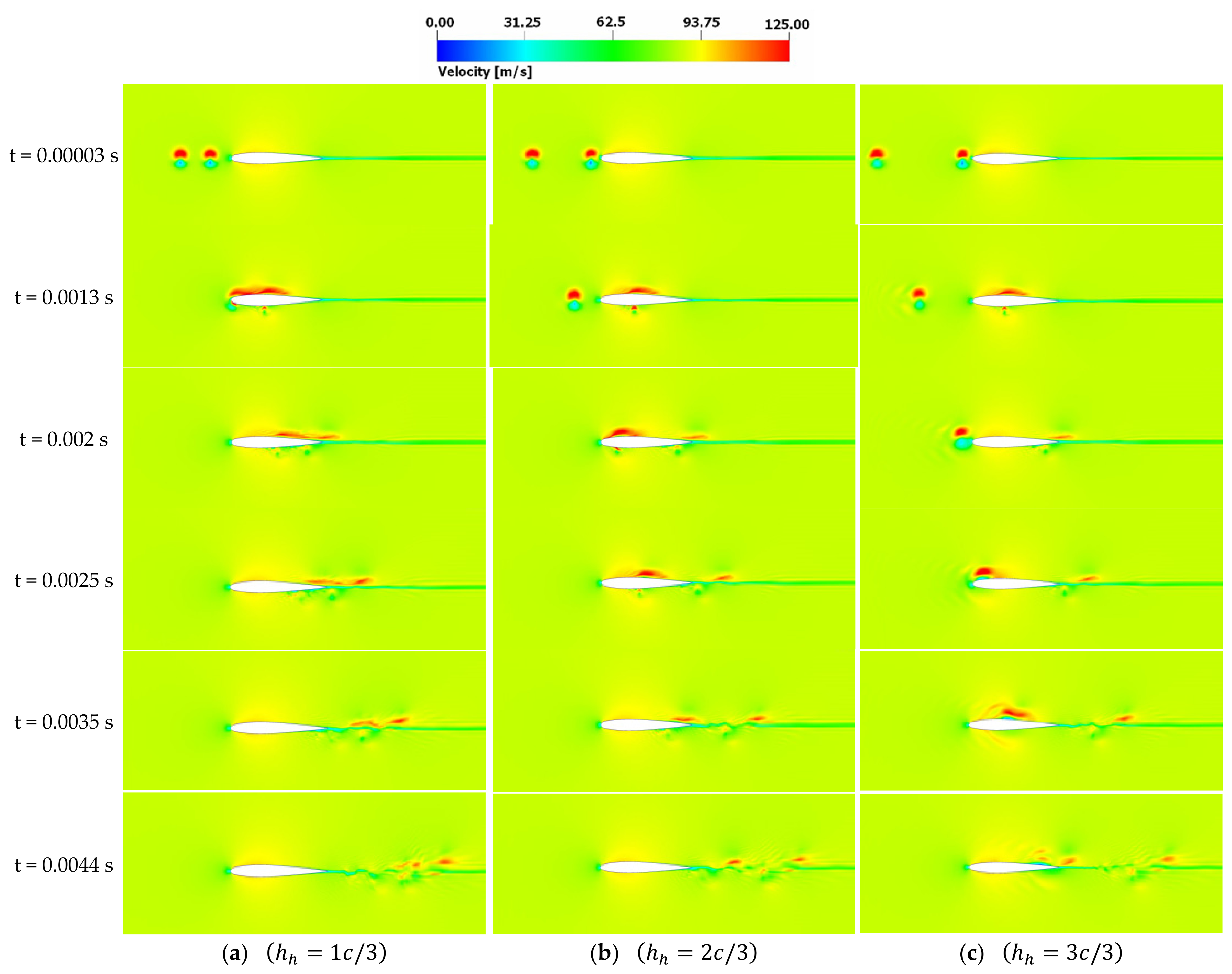
Figure 17 illustrates the instantaneous velocity fields for the three different horizontal offset distances in the blade–vortex-street interaction configuration. The flow field analysis reveals qualitative similarities between isolated rotor–vortex interactions and rotor–vortex-street interactions; in both cases, pronounced disturbances occur in the near field around the rotor disk and within the developing rotor wake. However, vortex-street interactions introduce more complex phenomena, such as vortex merging and multi-vortex coupling, which alter both the rotor–wake interaction and the resulting fluid dynamics. These interactions not only modify local velocity distributions and induced inflow across the rotor disk but also have measurable effects on aerodynamic performance metrics, including lift and drag coefficients. The comparison across the three offset distances highlights how decreasing horizontal spacing amplifies unsteady wake interactions, strengthens vortex merging, and increases the non-uniformity of the induced velocity field within the blade slipstream.
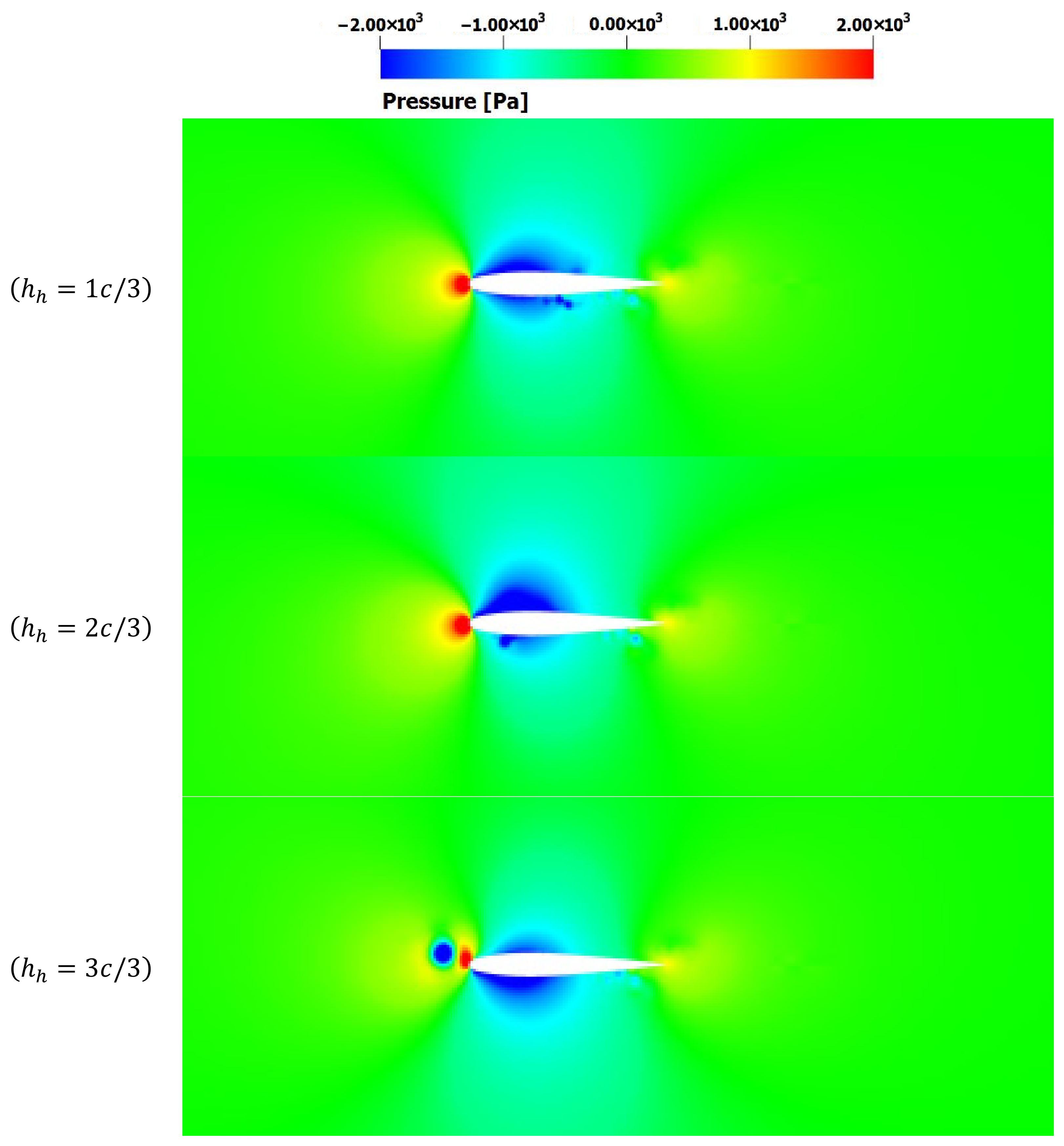
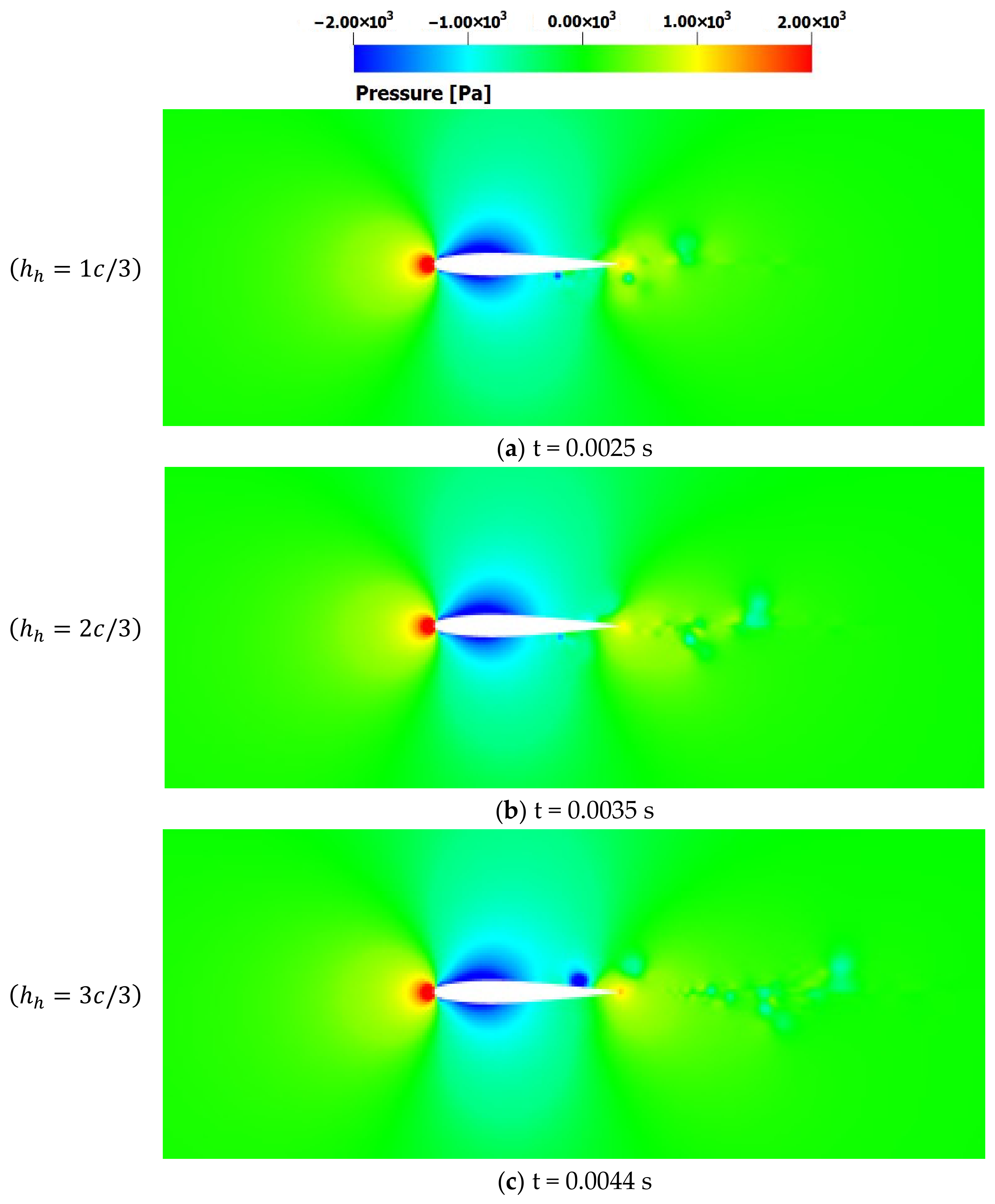
The horizontal offset distance between consecutively shed vortices has a strong influence on the quadrotor rotor flow field. The largest near-field and wake disturbances are observed for the smallest offset distance ( h h = 1 c / 3 ) , as shown in Figure 17 at t = 0.0013 s. Increasing the offset distance reduces the intensity of vortex merging, which is evident when comparing the velocity profiles at t = 0.0013 s h h = 1 c / 3 , t = 0.002 s h h = 2 c / 3 and t = 0.0025 s h h = 3 c / 3 . At t = 0.0044 s, the effect of horizontal offset h h on the rotor–vortex interaction becomes even more apparent. Thus, for the smallest offset, residual vortex components remain dynamic, generating strong wake disturbances, whereas for the largest offset, remnant vortex structures are highly scattered and dissipate rapidly. Comparing h h = 1 c / 3 at t = 0.0025 s with h h = 2 c / 3 at t = 0.0035 s, it demonstrates that horizontal spacing significantly affects blade–vortex interaction (BVI) and the induced velocity field, even when the second vortex impinges near the mid-chord while the first vortex has moved downstream.
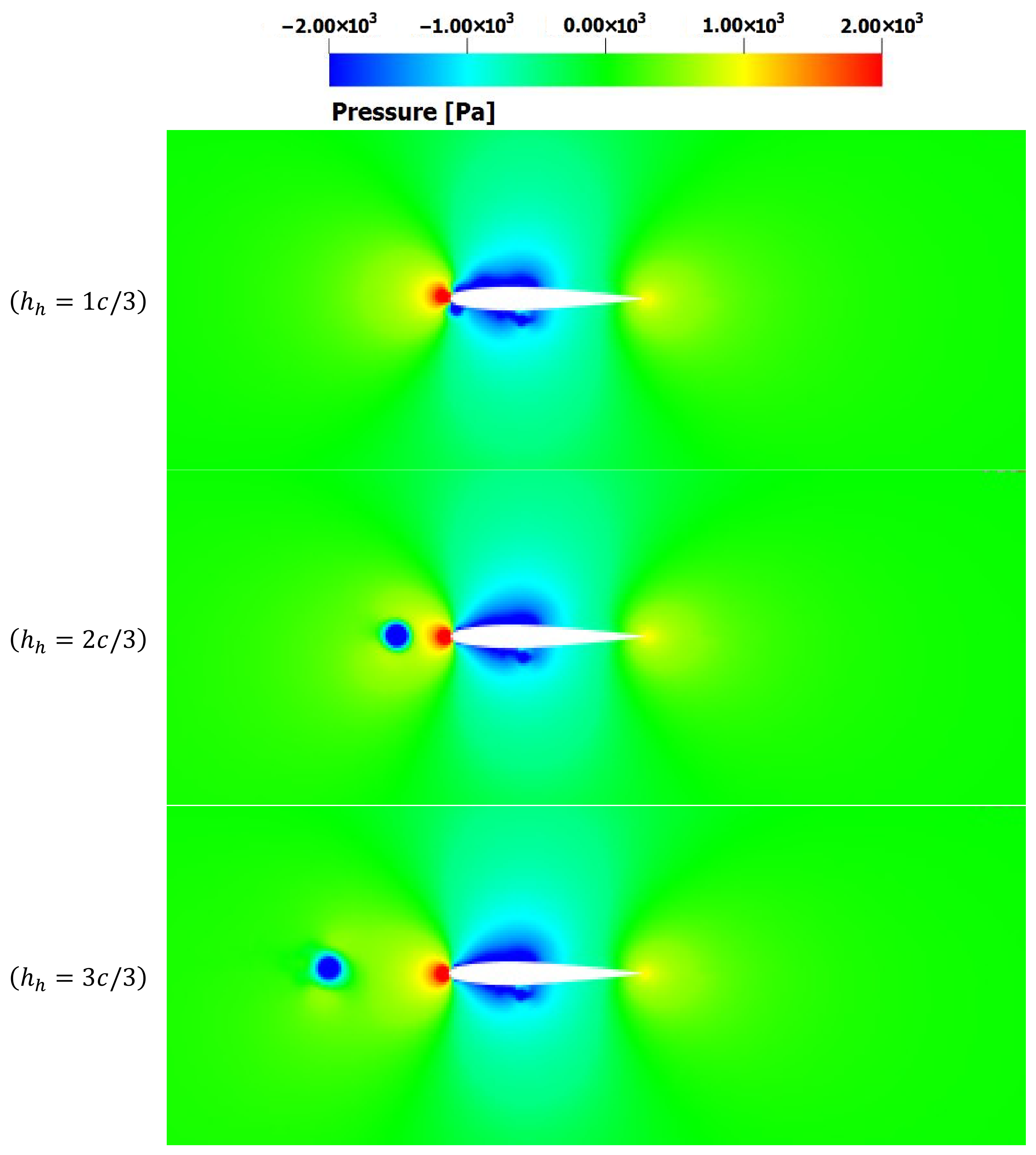
The influence of horizontal offset is further confirmed by comparing flow fields for h h = 1 c / 3 and h h = 3 c / 3 , where stronger flow disturbances and coherent vortical structures are observed for the smaller offset. These enhanced disturbances primarily result from the merging of remnant vortices with the rotor wake, increasing unsteady loading on the blades. When the horizontal offset exceeds the rotor blade chord ( h > c ), rotor–vortex-street interactions resemble isolated rotor–vortex encounters. Due to the nonlinear and unsteady nature of turbulent BVI in blade wakes, the linear superposition of individual interactions does not apply, and multi-vortex coupling effects dominate the near-wake dynamics.
Analysis of Pressure Field
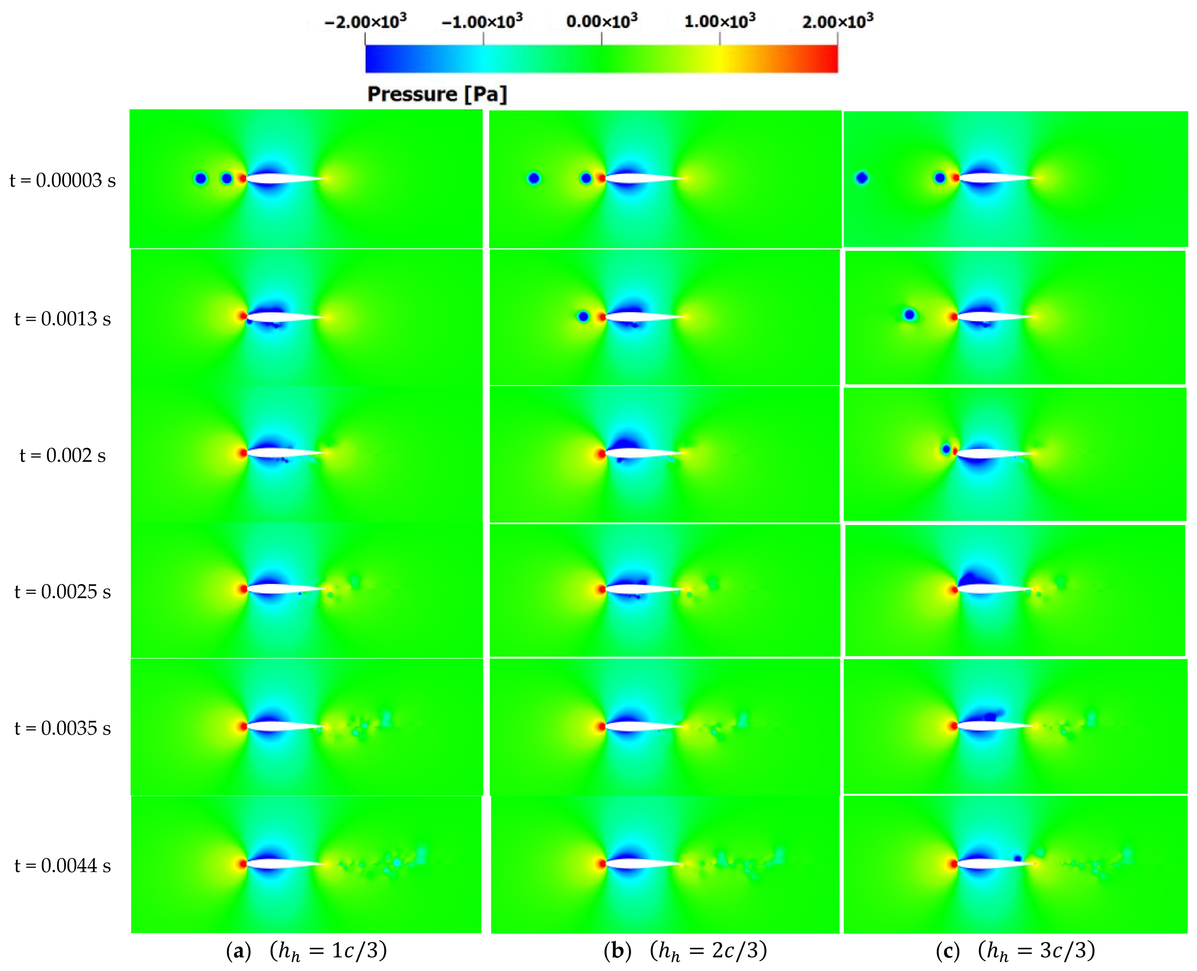
The pressure field dynamics observed across the three horizontal offset distances, as seen in Figure 18, have direct implications for rotor aerodynamic performance. As the first vortex interacts with the rotor blade, localized low-pressure regions develop on the suction side, generating unsteady lift and drag fluctuations as shown in Figure 19. The timing and intensity of the second vortex–blade interaction, controlled by the horizontal offset distance h h , modulate the magnitude of these fluctuations. For smaller offsets, the second vortex impinges on the blade shortly after the first, promoting stronger vortex merging and more pronounced pressure gradients. This results in increased unsteady loading, higher local induced velocities, and amplified variations in instantaneous lift and drag coefficients. In contrast, larger offsets delay secondary interactions, allowing remnant vortices to dissipate more before reaching the blade. Consequently, pressure gradients are weaker, unsteady aerodynamic loading is reduced, and wake disturbances are less pronounced. These observations indicate that horizontal vortex spacing is a critical parameter in rotor blade performance; thus, it governs not only the near-blade flow structure and vortex merging dynamics but also directly influences lift and drag coefficients. Optimizing rotor spacing or phasing in multirotor UAVs could therefore mitigate excessive unsteady loading and improve overall aerodynamic efficiency.
At t = 0.002 s, comparing h h = 1 c / 3 and h h = 3 c / 3 , the first vortex has already interacted with the airfoil for both cases. For h h = 1 c / 3 , the second vortex interaction causes a large negative pressure on the airfoil top surface, while for h h = 3 c / 3 , the negative pressure is observed beneath the airfoil. This is also well illustrated by the comparison of pressure fields for offset distances h h = 1 c / 3 and h h = 3 c / 3 , Figure 20. This demonstrates the effect of horizontal offset on vortex merging and vortex–airfoil interactions. Overall, vortex-street interactions generate small-scale vortical structures, as shown in Figure 18 for h h = 3 c / 3 .
The small-scale vortical structures generated during rotor–vortex-street interactions have a direct impact on blade aerodynamic performance. As these micro-vortices form and convect downstream, they induce localized fluctuations in blade loading, leading to unsteady variations in lift and drag coefficients. For smaller horizontal offsets h h = 1 c / 3 , where vortex merging is more pronounced, the amplitude of these fluctuations is greater due to stronger interactions between consecutive vortices and the rotor blade. In contrast, larger offsets h h = 2 c / 3 allow the remnant vortices to dissipate more, before impinging on the rotor, producing weaker small-scale vortical structures and correspondingly smaller fluctuations in lift and drag coefficients. This behavior demonstrates that the horizontal offset distance h h not only governs near-blade flow structures but also modulates unsteady aerodynamic forces and power requirements of the rotor. These results suggest that the careful design of rotor phasing and inter-rotor spacing could mitigate excessive unsteady loading, optimize wake coherence, and improve overall rotor aerodynamic efficiency, particularly under conditions where vortex-street interactions are prominent.
When tip vortices from adjacent rotors interact and merge, the local velocity field around the blades is significantly altered. These velocity changes directly influence the pressure distribution over the blade surfaces through unsteady aerodynamic effects: regions of higher velocity correspond to lower pressure, while regions of lower velocity correspond to higher pressure. Consequently, vortex merging modifies the pressure gradients acting on the blades, resulting in variations in lift and moment fluctuations. This explains why periods of vortex merging correlate with amplified or diminished unsteady aerodynamic loads, highlighting the intrinsic link between the velocity field and the pressure field in rotor–vortex interactions.
Figure 21 presents the comparison of the pressure field emphasizing the dynamics of rotor–vortex-street interactions and its impact on the wake dynamics. The comparison is made at the different instants to capture the vortex at the same physical location, with respect to the blade chord. The analysis of the pressure field reveals that, for horizontal offsets h h = 1 c / 3 and h h = 2 c / 3 , a remnant component of the second vortex is observed beneath the rotor blade, whereas for the largest offset h h = 3 c / 3 , it appears above the blade. The core size and circulation strength of the remnant vortex are the greatest for the smallest offset h h = 1 c / 3 , highlighting the influence of horizontal spacing on the timing, trajectory, and evolution of vortex remnants within the blade wake. Based on pressure field analysis, horizontal offset is expected to have a significant effect on rotor aerodynamic coefficients, including lift and drag coefficients. The following section presents a detailed assessment of these performance implications as a function of the horizontal vortex spacing.
Analysis of the Aerodynamic Coefficients for Single-Vortex and Vortex-Street Interactions
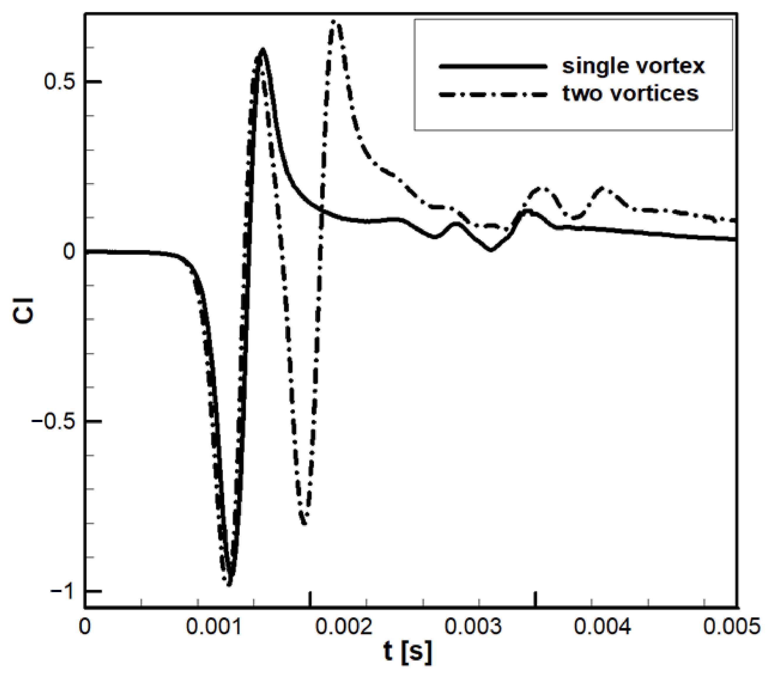
The impact of vortex-street interactions on the aerodynamic coefficients, lift and drag is presented in this section, along with a comparison to single-vortex interactions. Figure 22 illustrates the time-dependent lift coefficient for both cases. For the vortex-street interaction, results are shown at the horizontal offset h h = 1 c / 3 , with vortex cores aligned to the airfoil centerline.
The analysis of Figure 22 indicates that, when the vortex is upstream, the lift coefficient follows similar trends for both single-vortex and vortex-street interactions. As the vortex approaches the airfoil, the lift coefficient decreases steadily due to the induced velocity of the clockwise-rotating vortex, which produces a nose-down effect. Once the vortex core passes the leading-edge, the lift coefficient increases abruptly, reflecting sudden pressure changes associated with BVI noise. As shown in Figure 22, these changes are asymmetric; the lift coefficient first drops to a minimum of C l = − 1 , then rises to a maximum of C l = 0.6 . This asymmetry results from vortex distortion; the vortex core and strength diminish during the interaction, leaving the residual vortex too weak to restore the nose-up effect with an equal magnitude. As the residual vortex convects downstream along the chord, the lift coefficient decays asymptotically, with fluctuations observed at t = 0.004 s as the vortex leaves the airfoil. For vortex-street interactions, the first airfoil–vortex encounter shows a similar lift coefficient behavior to the single-vortex case. The second vortex interaction exhibits comparable dynamics, but the lift coefficient values are shifted upward due to vortex merging. This merging enhances the overall lift, particularly after the second vortex traverses the chord. Notably, the lift coefficient remains higher for vortex-street interactions than for single-vortex cases, even after the vortices have passed the airfoil (t = 0.003 s).
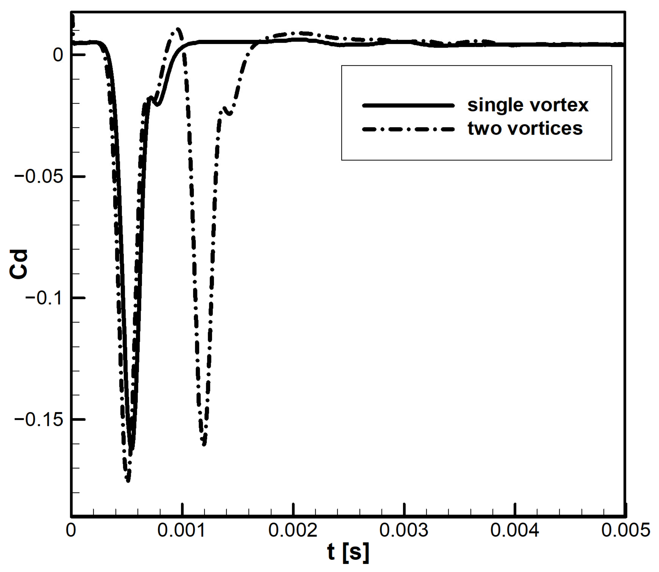
Figure 23 presents the drag coefficient comparison. For the first vortex interaction, both cases display similar behavior; thus, as the vortex approaches, drag coefficient decreases to a minimum of C d = − 0.16 for single-vortex and C d = − 0.175 for vortex-street interactions. Once the vortex passes the leading-edge, the drag coefficient rises abruptly. Negative drag values here correspond to flow separation and reverse flow induced by boundary-layer ejection and the clockwise vortex motion. In rotorcraft, such reverse flow triggers blade lead–lag motion, which adversely affects performance and stability and must be mitigated. For the single-vortex case, as the residual vortex crosses the chord, the drag coefficient stabilizes at C d ≈ 0.005 , lower than the uniform-flow drag coefficient of C d = 0.006 , for an NACA0012 airfoil at the same angle of attack. This reduction arises from the blade–vortex interaction and residual vortex observed in the pressure field, as shown in Figure 14 at t = 0.00196 s.
For vortex-street interactions, the first vortex shows the same drag behavior as the single-vortex case, but with a deeper minimum of C d = − 0.175 . During the second interaction, the minimum drag value increases to C d = − 0.16 , reflecting the influence of vortex merging and reverse flow. The reverse flow contributes positive drag, partially offsetting the earlier negative drag. As the residual vortices leave the chord, the drag coefficient converges to C d = 0.006 , consistent with the uniform-flow reference case.
Overall, these results indicate that vortex-street interactions amplify unsteady loading and modify both lift and drag distributions compared with isolated vortex interactions. The degree of horizontal offset and vortex merging strongly governs the amplitude and timing of these aerodynamic fluctuations, emphasizing the importance of rotor spacing and wake management in multirotor design.
The Effect of the Horizontal Offset Distance on the Aerodynamic Coefficients
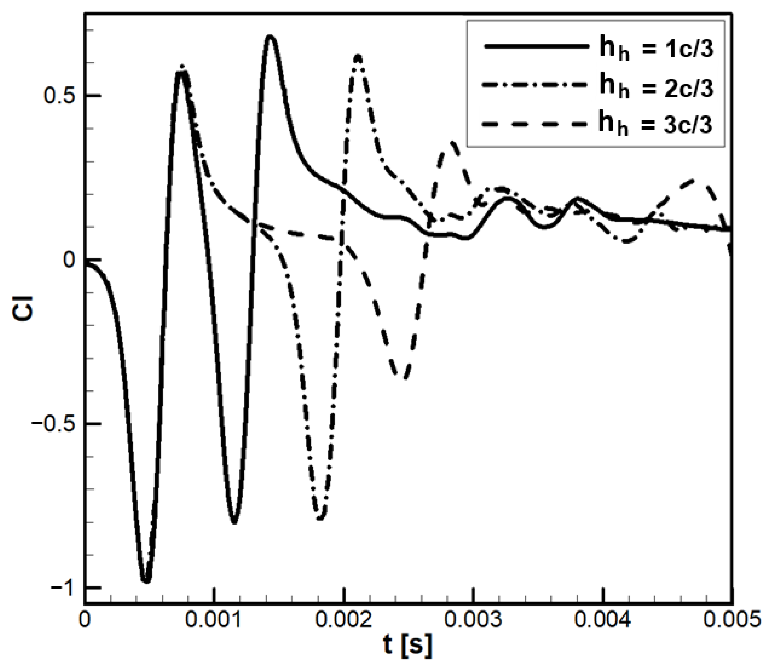
The following section examines the effect of horizontal offset distance on the aerodynamic coefficients of lift and drag. Figure 24 compares the time-dependent lift coefficient for three offset distances h h = 1 c / 3 , h h = 2 c / 3 and h h = 3 c / 3 . The first airfoil–vortex interaction shows nearly identical behavior across all offset distances, with similar values up to t = 0.00075 s. At offset distance h h = 1 c / 3 , the second interaction resembles the first but with an upward shift in lift coefficient due to vortex merging. For offset distance h h = 2 c / 3 , the second interaction produces a sudden change in lift, delayed in time because of the larger spacing. This sudden change is weaker than for the offset distance h h = 1 c / 3 , as the merging process disperses the vortices near the airfoil.
With further increase in offset distance h h = 3 c / 3 , the second interaction still causes a sharp change in lift, but with even lower magnitude. Here, the second vortex reaches the airfoil as the residual of the first vortex exits the trailing-edge. The opposing rotations of the residual (clockwise, nose-up) and the incoming vortex (nose-down) counteract each other, reducing the net effect on lift coefficient. Flow instabilities from the first interaction also influence the second, altering its dynamics. Although the magnitude of the sudden lift change decreases with offset distance, fluctuations in lift increase as the residual vortex departs the airfoil. These fluctuations arise from the interaction and merging of the two vortices in the vicinity of the airfoil.
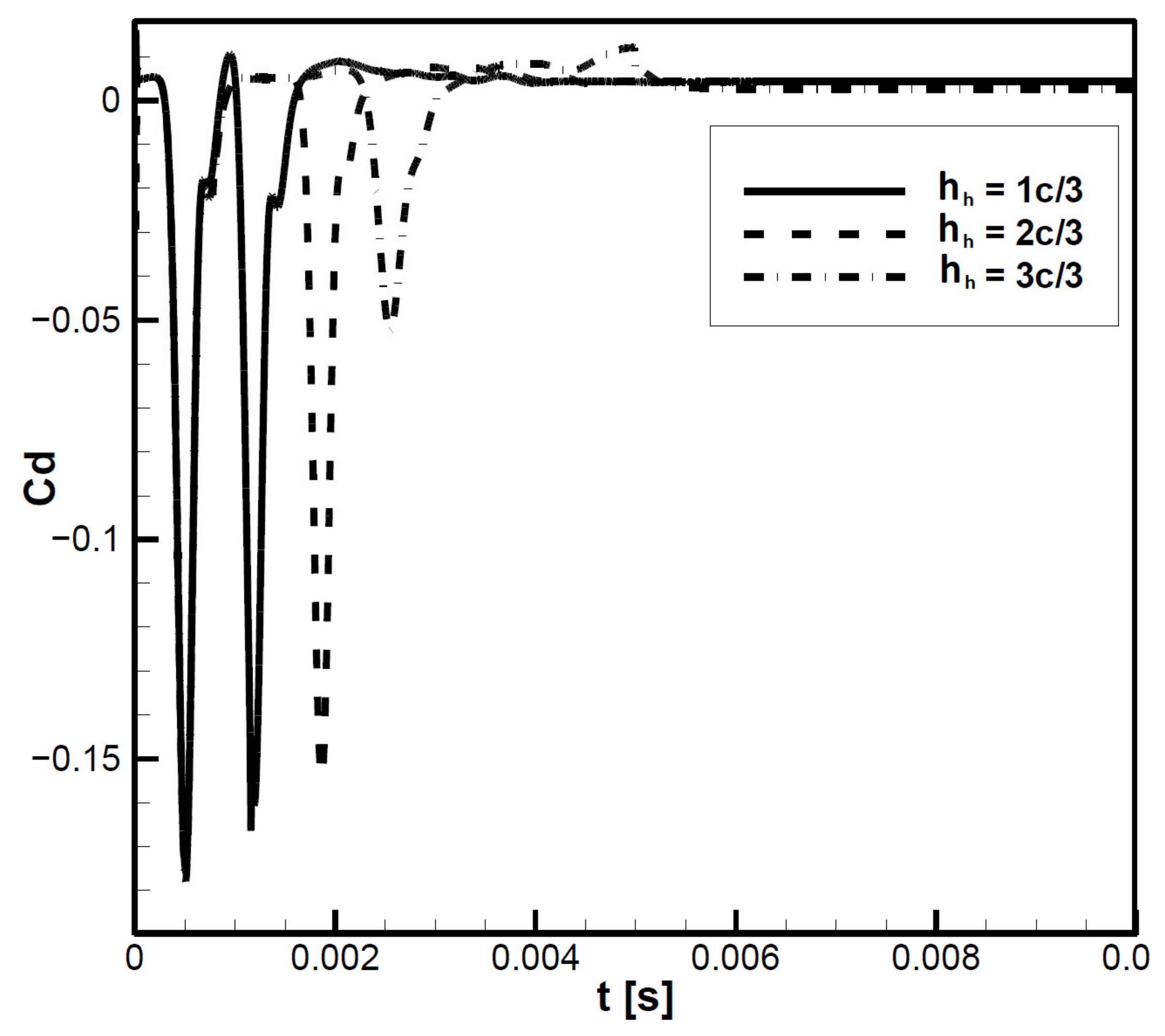
Figure 25 presents drag coefficient comparisons for the same offset distances h h = 1 c / 3 , h h = 2 c / 3 and h h = 3 c / 3 . Similar to lift coefficient, the first interaction yields nearly identical drag responses across all cases up to t = 0.0008 s. During the second interaction, however, differences emerge.
For the offset distance h h = 1 c / 3 , a sudden change occurs, with the minimum drag peak reaching C d = − 0.165 , higher than the first interaction peak of C d = − 0.175 , due to vortex merging. At the offset distance h h = 2 c / 3 , the minimum peak increases further to C d = − 0.1485 , while at the offset distance h h = 3 c / 3 , it reaches significantly higher values C d = − 0.05 compared to the other two cases.
Overall, increasing the offset distance weakens flow separation and reverse flow during the second interaction. These findings show that vortex spacing governs the merging process of successive vortices, which in turn strongly influences the aerodynamic coefficients.
Rotor–vortex-street interactions generate stronger near-wake turbulence and accelerate residual vortex dissipation compared with single-vortex interactions. These dynamics result in amplified unsteady loading on the rotor blades, with lift and drag fluctuations increasing by up to 60% at small horizontal offsets. Pressure fields reveal that micro-vortices formed through shear-layer instabilities redistribute vorticity, contributing to more rapid wake homogenization and altered inflow distributions.
These results demonstrate that horizontal rotor spacing is a critical design parameter. Offsets smaller than the blade chord produce strong vortex merging, enhancing lift fluctuations and potentially contributing to rotor instability and increased acoustic emissions. Larger offsets reduce unsteady loads and improve wake dissipation, suggesting that careful rotor phasing can optimize multirotor aerodynamic efficiency.
In the present study, lift coefficient comparisons are provided as a primary quantitative metric to assess the overall aerodynamic response and to demonstrate agreement with classical blade–vortex interaction (BVI) behavior. Detailed validation of velocity and vorticity fields is limited, as phase differences and finer flow-field discrepancies have not been quantified. This limitation arises because the simulations are based on a two-dimensional canonical airfoil rather than a full three-dimensional rotating rotor and because experimental velocity or vorticity data for the Reynolds number examined are unavailable. Despite these limitations, the qualitative trends observed in vortex merging, induced velocity amplification, and pressure field variations are consistent with established BVI phenomena reported in the literature [43,44,45,46,47,48,49,50,51]. Future work could extend the analysis to include quantitative phase comparisons, frequency-domain characterization, and full three-dimensional rotor simulations to provide a more comprehensive validation and to better assess unsteady aerodynamic loading relevant to rotorcraft noise, vibration, and structural effects.

4. Discussion

The present study focuses on simplified rotor–vortex interaction physics using a quasi-three-dimensional NACA0012 airfoil with imposed vortex streets, and does not incorporate full three-dimensional rotor kinematics, azimuthal variation, multirotor aerodynamics, or UAV control systems. Therefore, direct conclusions regarding flight stability, control strategies, noise, structural fatigue, or overall aerodynamic efficiency cannot be fully supported.
The primary goal of this work is to provide insights into the fundamental flow physics of rotor–vortex and rotor–vortex-street interactions, particularly the influence of horizontal vortex spacing on unsteady aerodynamic loading. Lift coefficient comparisons are provided as a quantitative metric, and observed trends in vortex merging, induced velocity amplification, and pressure field variations are consistent with well-established blade–vortex interaction (BVI) phenomena [43,44,45,46,47,48,49,50,51]. Comprehensive validation of velocity fields, vortex dynamics, or phase errors is limited by the lack of available experimental or high-fidelity LES data for comparable canonical or quadrotor configurations. The analysis is largely qualitative, and future work could extend this study through detailed frequency, spectral, and statistical analyses of unsteady loads, which are particularly relevant for rotorcraft noise, vibration, and structural loading.
The results of this study provide a detailed characterization of rotor–vortex and rotor–vortex-street interactions in BVI configurations, highlighting how multi-vortex coupling influences both local flow physics and overall aerodynamic performance. The discussion is structured around three main themes, i.e., (i) flow-field dynamics, (ii) vortex merging and (iii) wake evolution, and their implications for aerodynamic coefficients and performance. Finally, key insights and design implications are presented.

4.1. Flow-Field Dynamics and Vortex Merging

Analysis of the velocity and pressure fields demonstrates that rotor–vortex-street interactions produce fundamentally different wake dynamics compared with isolated rotor–vortex encounters. In vortex-street configurations, successive tip vortices interact with one another before impinging on the rotor blades, leading to vortex stretching, deformation, and partial merging. This multi-vortex coupling enhances local velocity gradients on the blade suction side and generates intensified low-pressure regions near the leading-edge, producing stronger unsteady aerodynamic loading. By contrast, isolated rotor–vortex interactions maintain higher vortex coherence, leading to more concentrated pressure peaks and prolonged wake structures downstream. The horizontal offset distance between consecutively shed vortices emerges as a critical parameter controlling the intensity and timing of these interactions. Smaller offsets result in stronger vortex merging, larger residual vortex cores, and more pronounced near-blade disturbances, whereas larger offsets allow residual vortices to dissipate before reaching the blade, reducing the magnitude of unsteady flow features. These findings underscore the nonlinear nature of multirotor wake interference, where superposition of single-vortex effects does not adequately describe the flow field, particularly when rotor wakes overlap.

4.2. Wake Evolution and Micro-Vortical Structures

The interaction of consecutive vortices in a rotor–vortex street accelerates the redistribution of vorticity within the blade slipstream. Micro-vortices generated by shear-layer instabilities and vortex merging propagate downstream, interacting with the primary rotor wake and promoting the rapid dissipation of coherent structures. This enhanced turbulence intensity and multi-scale vorticity coupling increase wake complexity and influence the induced inflow distribution across the rotor disk. Consequently, rotor–vortex-street interactions create a more turbulent and non-uniform wake environment than isolated blade–vortex encounters, which has direct implications for inter-rotor interference in BVI configurations. These effects are particularly pronounced for small horizontal offsets, where residual vortices maintain significant circulation and interact strongly with subsequent blades. Larger offsets reduce the amplitude of micro-vortical structures, leading to weaker unsteady loading and a more stable downstream slipstream. This observation highlights the importance of carefully controlling rotor spacing and phasing in multirotor UAVs to manage wake interactions effectively.

4.3. Implications for Aerodynamic Coefficients

The unsteady flow structures induced by rotor–vortex-street interactions directly affect aerodynamic coefficients such as lift and drag. In particular, vortex merging significantly alters the aerodynamic loads. When vortices interact and merge, the local velocity field near the blade surface is modified, producing regions of accelerated flow and intensified velocity gradients. According to Bernoulli’s principle, these velocity variations generate corresponding low-pressure regions on the suction side and transient changes in lift and drag. Consequently, stronger vortex merging produces larger fluctuations in aerodynamic forces, whereas weaker interactions result in more moderate load variations.
This highlights the intrinsic relationship between the pressure and velocity fields: local increases in flow velocity reduce pressure and increase suction on the blade surface, while slower flow regions correspond to higher pressure. This coupling explains the observed unsteady loading patterns and demonstrates why horizontal vortex spacing and phasing are critical parameters for managing aerodynamic forces in multirotor configurations.
Understanding these aerodynamic mechanisms is essential for practical UAV design. The amplified unsteady loads due to vortex merging can influence rotor blade fatigue, structural vibration, and noise generation, as well as affecting flight stability and control response. By quantifying these effects, designers can optimize rotor spacing, phasing, and blade configurations to mitigate adverse aerodynamic loads, improve vibration damping, and enhance overall UAV performance and reliability.

4.4. Material and Structural Considerations

While the preceding sections focused on the aerodynamic mechanisms of rotor–vortex and rotor–vortex-street interactions, the material properties of UAV wings/blades can significantly influence the manifestation and mitigation of unsteady aerodynamic loads. Fixed-wing UAVs commonly use laminated composites with extruded polystyrene (XPS) cores reinforced by carbon or glass fiber epoxy layers, providing a combination of high in-plane stiffness and vibration damping [31]. This approach can also be extended to quadrotor UAV blades, where the stiffness ensures the effective transmission of aerodynamic loads, and the damping properties reduce structural vibrations induced by blade–vortex interactions (BVIs).
Cork-based or hybrid cork–carbon composites offer environmentally friendly alternatives with enhanced energy absorption, vibration damping, and thermal protection [32]. Incorporating these materials in UAV blades can lower the amplitude of unsteady loading, improve fatigue resistance, and complement the aerodynamic control strategies.
Integrating material considerations with aerodynamic insights highlights the importance of a combined aero-structural perspective. For example, a smaller horizontal vortex spacing, which intensifies vortex merging and micro-vortical structures, may impose higher unsteady loads on the blades. High-damping composite and cork-based materials can attenuate these loads, improving flight stability, reducing structural fatigue, and enhancing overall UAV performance. This emphasizes the potential of tailoring material properties alongside rotor layout optimization in multirotor UAV design.

4.5. Key Insights and Design Implications

  • Nonlinear wake interference dominates near-blade flow dynamics: Multi-vortex coupling in rotor–vortex-street interactions cannot be approximated as linear superposition, emphasizing the need for careful rotor placement and timing in multirotor UAV design.
  • Horizontal vortex spacing governs BVI intensity: Smaller offsets increase vortex merging, micro-vortex formation, and unsteady loading, while larger offsets allow residual vortices to dissipate, reducing peak aerodynamic fluctuations.
  • Wake management is critical for performance and stability: By controlling inter-rotor spacing and rotor phasing, designers can mitigate high amplitude lift and drag fluctuations, optimize wake coherence, and reduce unsteady loading on downstream blades.
  • Micro-vortical structures influence downstream flow: The formation and interaction of small-scale vortices significantly modify slipstream characteristics, which can impact inter-rotor interference, power requirements, and rotor wake-induced instabilities.
  • Material and damping properties modulate unsteady loads: Composite and cork-based materials in rotor blades can attenuate aerodynamic load fluctuations, reduce vibration-induced fatigue, and enhance structural resilience, particularly under conditions of strong vortex merging and micro-vortical activity. Tailoring material properties in conjunction with rotor layout optimization can improve both aerodynamic performance and flight stability.
This study extends classical BVI research by investigating rotor–vortex-street interactions, where multiple consecutively shed vortices interact with rotor blades, producing nonlinear multi-vortex coupling effects. The horizontal vortex offset distance is identified as a key parameter that governs distinct aerodynamic interaction regimes, with strong coupling occurring when the offset approaches the blade chord. Vortex-street interactions fundamentally alter wake evolution and aerodynamic loading, enhancing vorticity redistribution, micro-scale vortex formation, and lift and drag fluctuations. Finally, the analysis directly links flow physics to performance metrics, providing practical insights for rotor spacing and phasing not typically captured in conventional BVI studies.
The observed unsteady aerodynamic phenomena, vortex merging, amplified lift and drag fluctuations, and localized pressure peaks, are strongly influenced by horizontal vortex spacing. A smaller spacing intensifies multi-vortex interactions, leading to increased rotor vibrations that can affect flight stability and control responsiveness, accelerate structural fatigue in blades and supporting components, and contribute to elevated noise emissions. Conversely, a larger spacing allows residual vortices to dissipate, mitigating unsteady loading and reducing these adverse effects. These insights highlight the importance of carefully selecting rotor spacing and phasing in multirotor UAVs to optimize aerodynamic performance, enhance control strategies, minimize noise, and improve structural durability. Accordingly, the findings provide practical guidance for rotor layout design, suggesting that spacing and phasing can be strategically adjusted to balance aerodynamic efficiency, flight stability, and structural longevity in UAV systems.
We recognize that the fixed-blade assumption does not capture full rotor kinematics or azimuthal variation. However, this simplification is intentional and methodologically justified, as it allows us to isolate and systematically study the fundamental physics of vortex–airfoil interactions, including vortex distortion, merging, and wake-induced unsteady loading. Similar fixed-blade approaches have been validated in previous studies [40,43,44,45,46,47,48,49,50], demonstrating that they can accurately capture the qualitative features of near-blade vortex dynamics. Despite the absence of full rotation and realistic inflow, the findings provide robust qualitative insights into residual vortex behavior and the role of vortex spacing on unsteady aerodynamic forces, phenomena directly relevant to rotor layout, wake interference management, and preliminary UAV design considerations. This study therefore establishes a controlled baseline for understanding complex multi-vortex effects, which can be quantitatively extended in future work to fully rotating three-dimensional rotor systems.
While the present study primarily focuses on the qualitative visualization of velocity and pressure fields to elucidate the mechanisms of vortex–airfoil and vortex-street interactions, time histories of lift and drag coefficients provide a first-order quantitative assessment of aerodynamic performance. We note that additional analyses, such as spectral characterization, frequency-domain evaluation, and statistical measures of unsteady loads, represent a valuable extension for future work, particularly for assessing rotorcraft noise, vibration, and structural loading. These future analyses will complement the current results by providing a more comprehensive quantification of unsteady aerodynamic effects in multirotor UAV configurations.
In summary, this study establishes a strong coupling between rotor–vortex-street interactions, horizontal vortex spacing, and unsteady aerodynamic performance. The findings provide quantitative and qualitative guidance for rotor layout optimization, wake interference management, flight path management, and predictive modeling of multirotor aerodynamic behavior.

5. Conclusions

This study systematically investigated rotor–vortex and rotor–vortex-street interactions, emphasizing the effects of multi-vortex coupling on both the flow physics and aerodynamic performance. The time-resolved analyses of velocity and pressure fields, together with the measurements of lift and drag coefficients, revealed the critical influence of vortex spacing and wake interference on rotor behavior.
Rotor–vortex-street interactions were found to generate substantially stronger unsteady aerodynamic loading than isolated rotor–vortex encounters. The interaction of successive tip vortices with rotor blades produced intensified velocity gradients and localized low-pressure regions on the blade suction side, leading to amplified fluctuations in lift and drag. The horizontal spacing between consecutively shed vortices was identified as a dominant factor governing the interaction intensity. Small offsets caused pronounced vortex merging, larger residual vortex cores, and more severe near-blade disturbances, while larger offsets allowed residual vortices to dissipate before impinging on the blade, thereby reducing unsteady loading and enhancing wake uniformity.
This study also demonstrated that multi-vortex interactions accelerate the breakdown of coherent vortex structures and promote the formation of micro-vortical features within the rotor slipstream. These processes increase turbulence intensity, modify the induced inflow distribution across the rotor disk, and influence downstream rotor performance and inter-rotor interference. The effects of these interactions were clearly reflected in the aerodynamic coefficients, with lift and drag coefficients exhibiting larger fluctuations in vortex-street scenarios compared with single-vortex encounters. The amplitude and timing of these fluctuations were strongly dependent on horizontal vortex spacing, confirming that the careful control of rotor phasing and spacing is critical for managing wake interference in multirotor UAVs. These findings have direct implications for rotor design and operation.
Controlling horizontal spacing and rotor layout can mitigate excessive unsteady loading, reduce torque fluctuations, and maintain vehicle stability, particularly in configurations where rotors operate in close proximity or generate dense vortex wakes. Moreover, the accurate modeling of multi-vortex interactions is essential for predictive performance estimation and for developing strategies to optimize aerodynamic efficiency. Overall, this work establishes that rotor–vortex-street interactions are a key determinant of unsteady aerodynamic behavior in rotorcraft and that their careful management can enhance efficiency, stability, and control in multirotor flight.
This study examined rotor–vortex-street interactions and fundamental rotor–vortex interaction physics using a quasi-three-dimensional NACA0012 airfoil with imposed vortex streets, without modeling full 3D rotor kinematics, multirotor effects, or UAV control. The horizontal vortex offset was identified as a key parameter, with the strongest coupling observed when comparable to the blade chord. These interactions significantly influence wake dynamics, enhance vorticity redistribution, and modulate unsteady aerodynamic loading, including trends in lift, drag, vortex merging, induced velocities, and pressure fields consistent with established BVI behavior. While direct conclusions on flight stability, noise, or efficiency are not possible due to the simplified model and limited validation data, the analysis provides qualitative insights into key BVI phenomena and establishes a controlled baseline for rotor–vortex and vortex-street interactions. The results link flow physics to rotor performance, offering practical guidance for rotor spacing and phasing, and can be extended in future studies through broader operating conditions, three-dimensional effects, and spectral or statistical analyses relevant to rotorcraft vibration, noise, and structural loading.
This study used a fixed-blade framework with superimposed vortices to investigate fundamental blade–vortex interaction (BVI) physics. While full rotor kinematics and azimuthal variation were not included, this simplification allowed the isolation of key phenomena such as vortex distortion, merging, and wake-induced unsteady loading, consistent with prior studies. The results provide qualitative insights into residual vortex behavior and the influence of vortex spacing on unsteady aerodynamic forces, relevant to rotor layout, wake interference, and preliminary UAV design. This methodology establishes a controlled baseline for multi-vortex effects, which can be extended in future work to fully rotating, three-dimensional rotor systems.
It is important to note that the present study employs two-dimensional airfoil simulations to investigate fundamental rotor–vortex interactions. While the results provide qualitative insights into unsteady loading, wake interference, and the influence of horizontal vortex spacing, they do not directly translate to full three-dimensional quadrotor design, control, or structural performance. Nonetheless, these findings can inform preliminary design considerations such as rotor spacing, phasing, and potential trends in unsteady aerodynamic loading. Furthermore, understanding these unsteady flow features can support future studies on structural response and vibration mitigation, including the integration of advanced damping materials or composite structures, to reduce fatigue and enhance UAV durability. Future work incorporating three-dimensional, rotating rotors with realistic inflow and inter-rotor interactions will be necessary to quantitatively assess control strategies, noise generation, and structural fatigue in operational UAVs.

Funding

This research received no external funding.

Data Availability Statement

The original contributions presented in this study are included in the article. Further inquiries can be directed to the corresponding author.

Conflicts of Interest

The author declares no conflicts of interest.

References

  1. Hassanalian, M.; Abdelkefi, A. Classifications, applications, and design challenges of drones: A review. Prog. Aerosp. Sci. 2017, 91, 99–131. [Google Scholar] [CrossRef] [Scilit]
  2. Hassanalian, M.; Rice, D.; Abdelkefi, A. Evolution of space drones for planetary exploration: A review. Prog. Aerosp. Sci. 2018, 97, 61–105. [Google Scholar] [CrossRef] [Scilit]
  3. Johnson, W. Helicopter Theory; Dover Publications: New York, NY, USA, 1994. [Google Scholar]
  4. Dbouk, T.; Drikakis, D. Computational aeroacoustics of quadcopter drones. Appl. Acoust. 2022, 192, 108738. [Google Scholar] [CrossRef] [Scilit]
  5. Shukla, D.; Komerath, N. Multirotor drone aerodynamic interaction investigation. Drones 2018, 2, 43. [Google Scholar] [CrossRef] [Scilit]
  6. Li, W.; Wu, B. Computational fluid dynamics investigation of aerodynamics for agricultural drones. Comput. Electron. Agric. 2024, 227, 109528. [Google Scholar] [CrossRef] [Scilit]
  7. Li, W.; Wu, B. Computational fluid dynamics investigation of pesticide spraying by agricultural drones. Comput. Electron. Agric. 2024, 227, 109506. [Google Scholar] [CrossRef] [Scilit]
  8. Shouji, C.; Dafsari, R.A.; Yu, S.-H.; Choi, Y.; Lee, J. Mean and turbulent flow characteristics of downwash air flow generated by a single rotor blade in agricultural drones. Comput. Electron. Agric. 2021, 190, 106471. [Google Scholar] [CrossRef] [Scilit]
  9. Leishman, J.G. Principles of Helicopter Aerodynamics, 2nd ed.; Cambridge University Press: Cambridge, UK, 2006. [Google Scholar]
  10. Peters, D.A.; HaQuang, N. Technical Note: Dynamic inflow for practical applications. J. Am. Helicopter Soc. 1988, 33, 64–68. [Google Scholar] [CrossRef] [Scilit]
  11. Bagai, A.; Leishman, J.G. Flow visualization of compressible vortex structures using density gradient techniques. Exp. Fluids 1993, 15, 431–442. [Google Scholar] [CrossRef] [Scilit]
  12. Horner, M.B.; Galbraith, R.A.; Coton, F.N.; Stewart, J.N.; Grant, I. Examination of vortex deformation during blade–vortex interaction. AIAA J. 1996, 34, 1188–1194. [Google Scholar] [CrossRef] [Scilit]
  13. Renzoni, P.; Mayle, R.E. Incremental force and moment coefficients for a parallel blade–vortex interaction. AIAA J. 1991, 29, 6–13. [Google Scholar] [CrossRef] [Scilit]
  14. Seath, D.D.; Kim, J.-M.; Wilson, D.R. Investigation of the parallel blade–vortex interaction at low speed. J. Aircr. 1989, 26, 328–333. [Google Scholar] [CrossRef] [Scilit]
  15. Ramasamy, M.; Lee, T.E.; Leishman, J.G. Flow field of a Rotating-Wing Micro Air Vehicle. J. Aircr. 2007, 44, 1236–1244. [Google Scholar] [CrossRef] [Scilit]
  16. Branlard, E.; Gaunaa, M. Superposition of vortex cylinders for steady and unsteady simulation of rotors of finite tip-speed ratio. Wind Energy 2016, 19, 1307–1323. [Google Scholar] [CrossRef] [Scilit]
  17. Caradonna, F.X.; Kitaplioglu, C.; McCluer, M. An Experimental Study of Parallel Blade-Vortex Interaction Aerodynamics and Acoustics Utilizing an Independently Generated Vortex; NASA TM 1999-208790; NASA: Washington, DC, USA, 1999.
  18. Abelló, J.C.; George, A.R. Rotorcraft BVI noise reduction by attitude modification. In Proceedings of the 5th AIAA/CEAS Aeroacoustics Conference and Exhibit, Bellevue, WA, USA, 10–12 May 1999. [Google Scholar]
  19. Abelló, J.; George, A. Wake displacement study of attitude and flight parameter modifications to reduce rotorcraft blade–vortex interaction (BVI) noise. In Proceedings of the 9th AIAA/CEAS Aeroacoustics Conference and Exhibit, Hilton Head, SC, USA, 12–14 May 2003. [Google Scholar]
  20. Johnson, W. Calculation of blade–vortex interaction airloads on helicopter rotors. J. Aircr. 1989, 26, 470–475. [Google Scholar] [CrossRef] [Scilit] [PubMed]
  21. Oh, W.; Kim, J.S.; Kwon, O.J. Numerical simulation of two-dimensional blade–vortex interactions using unstructured adaptive meshes. AIAA J. 2002, 40, 474–480. [Google Scholar] [CrossRef] [Scilit] [PubMed]
  22. Lyrintzis, A.; Xue, Y. Study of noise mechanisms of transonic blade–vortex interactions. AIAA J. 1990, 28, 1562–1572. [Google Scholar] [CrossRef] [Scilit] [PubMed]
  23. Caprace, D.-G.; Ning, A.; Chatelain, P.; Winckelmans, G. Effects of rotor–airframe interaction on the aeromechanics and wake of a quadcopter in forward flight. Aerosp. Sci. Technol. 2022, 130, 107899. [Google Scholar] [CrossRef] [Scilit]
  24. Liu, C.; Li, B.; Wei, Z.; Zhang, Z.; Shan, Z.; Wang, Y. Effects of wake separation on aerodynamic interference between rotors in urban low-altitude UAV formation flight. Aerospace 2024, 11, 865. [Google Scholar] [CrossRef] [Scilit]
  25. Paz, C.; Suarez, E.; Gil, C.; Baker, C. CFD analysis of the aerodynamic effects on the stability of the flight of a quadcopter UAV in the proximity of walls and ground. J. Wind Eng. Ind. Aerodyn. 2020, 206, 104378. [Google Scholar] [CrossRef] [Scilit]
  26. Paz, C.; Suarez, E.; Gil, C.; Vence, J. Assessment of the methodology for the CFD simulation of the flight of a quadcopter UAV. J. Wind Eng. Ind. Aerodyn. 2021, 218, 104776. [Google Scholar] [CrossRef] [Scilit]
  27. Mori, R.; Takii, A.; Yamakawa, M.; Asao, S.; Takeuchi, S.; Kobayashi, Y.; Chung, Y.M. Flow field analysis of vortex ring state through descent experiments and simulations with a quadcopter. J. Comput. Sci. 2025, 85, 102528. [Google Scholar] [CrossRef] [Scilit]
  28. Lardeau, S.; Leschziner, M.A. Unsteady Reynolds–averaged Navier–Stokes computations of transitional wake/blade interaction. AIAA J. 2004, 42, 1559–1571. [Google Scholar] [CrossRef] [Scilit]
  29. Germano, M.; Piomelli, U.; Moin, P.; Cabot, W.H. A dynamic subgrid-scale eddy viscosity model. Phys. Fluids A 1991, 3, 1760–1765. [Google Scholar] [CrossRef] [Scilit]
  30. Spalart, P.R. Detached-eddy simulation. Annu. Rev. Fluid Mech. 2009, 41, 181–202. [Google Scholar] [CrossRef] [Scilit]
  31. Karpenko, M.; Stosiak, M.; Deptuła, A.; Urbanowicz, K.; Nugaras, J.; Królczyk, G.; Żak, K. Performance evaluation of extruded polystyrene foam for aerospace engineering applications using frequency analyses. Int. J. Adv. Manuf. Technol. 2023, 126, 5515–5526. [Google Scholar] [CrossRef] [Scilit]
  32. Karpenko, M.; Nugaras, J. Vibration damping characteristics of the cork-based composite material in line to frequency analysis. J. Theor. Appl. Mech. 2022, 60, 593–602. [Google Scholar] [CrossRef] [Scilit]
  33. Troldborg, N.; Sørensen, J.N.; Mikkelsen, R. Numerical simulations of wake characteristics of a wind turbine in uniform inflow. Wind Energy 2010, 13, 86–99. [Google Scholar] [CrossRef] [Scilit]
  34. Thom, A.; Duraisamy, K. High-resolution simulations of parallel blade–vortex interactions. AIAA J. 2010, 48, 2313–2324. [Google Scholar] [CrossRef] [Scilit]
  35. Bernandini, G.; Serafini, J.; Gennaretti, M.; Ianniello, S. Aeroelastic modeling effect in rotor BVI noise prediction. In Proceedings of the 12th AIAA/CEAS Aeroacoustics Conference (27th AIAA Aeroacoustics Conference), Cambridge, MA, USA, 8–10 May 2006. [Google Scholar]
  36. Dorange, A.; Benoit, C.; Garnier, E. High-fidelity computational aerodynamics of micro unmanned aerial vehicle propeller. Comput. Fluids 2025, 297, 106649. [Google Scholar] [CrossRef] [Scilit]
  37. Wolf, C.C.; Schanz, D.; Schwarz, C.; Heintz, A.; Bosbach, J.; Strübing, T.; Schröder, A. Volumetric wake investigation of a free-flying quadcopter using shake-the-box Lagrangian particle tracking. Exp. Fluids 2024, 65, 152. [Google Scholar] [CrossRef] [Scilit]
  38. Zarri, A.; Erba, E.; Munters, W.; Schram, C. Aeroacoustic installation effects in multi-rotorcraft: Numerical investigations of a small-size drone model. Aerosp. Sci. Technol. 2022, 128, 107762. [Google Scholar] [CrossRef] [Scilit]
  39. Tanabe, Y.; Sugawara, H.; Sunada, S.; Yonezawa, K.; Tokutake, H. Quadrotor Drone Hovering in Ground Effect. J. Robot. Mechatron. 2021, 33, 339–347. [Google Scholar] [CrossRef] [Scilit]
  40. Ilie, M. Fluid-structure interaction in turbulent flows; a CFD based aeroelastic algorithm using LES. Appl. Math. Comput. 2019, 342, 309–321. [Google Scholar] [CrossRef] [Scilit]
  41. Castells, C.; Richez, F.; Costes, M. A Numerical Investigation of the Influence of the Blade-Vortex Interaction on the Dynamic Stall Onset. J. Am. Helicopter Soc. 2021, 66, 1–13. [Google Scholar] [CrossRef] [Scilit]
  42. Colli, A.; Zanotti, A.; Gibertini, G. Wind Tunnel Experiments on Parallel Blade–Vortex Interaction with Static and Oscillating Airfoil. Fluids 2024, 9, 111. [Google Scholar] [CrossRef] [Scilit]
  43. Bian, W.; Zhao, G.; Chen, X.; Wang, B.; Zhao, Q. High-fidelity simulation of blade vortex interaction of helicopter rotor based upon TENO scheme. Chin. J. Aeronaut. 2023, 36, 275–292. [Google Scholar] [CrossRef] [Scilit]
  44. Liu, Y.; Caoa, N.; Wanga, Q.; Li, B. Numerical Simulation of Two-Dimensional Parallel Blade-Vortex Interactions Using Large Eddy Simulation. Procedia Eng. 2012, 31, 703–707. [Google Scholar] [CrossRef] [Scilit]
  45. Aboelkassem, Y. Blade-vortex interactions: Experimental Measurements of the Near-Flow Field. J. Fluid Sci. Technol. 2009, 4, 138–155. [Google Scholar] [CrossRef] [Scilit]
  46. Xu, Z.; Chang, M.; Bai, J.; Wang, B. Computational Investigation of Blade–Vortex Interaction of Coaxial Rotors for eVTOL Vehicles. Energies 2022, 15, 7761. [Google Scholar] [CrossRef] [Scilit]
  47. Ilie, M. Reduction of rotorcraft BVI using synthetic jets; computational studies using LES. Int. J. Comput. Methods Eng. Sci. Mech. 2024, 25, 105–123. [Google Scholar] [CrossRef] [Scilit]
  48. Yildirim, E.; Hillier, R. Numerical Investigation of 2D/3D Blade-Vortex Interactions. In Proceedings of the 28th International Symposium on Shock Waves, Manchester, UK, 17–22 July 2011; Kontis, K., Ed.; Springer: Berlin/Heidelberg, Germany, 2012. [Google Scholar] [CrossRef] [Scilit]
  49. Booth, E.R. Experimental observations of two-dimensional blade-vortex interaction. AIAA J. 1990, 28, 1353–1359. [Google Scholar] [CrossRef] [Scilit]
  50. Srinivasan, G.R.; McCroskey, W.J.; Baeder, J.D. Aerodynamics of two-dimensional blade-vortex interaction. AIAA J. 1986, 24, 1569–1576. [Google Scholar] [CrossRef] [Scilit]
  51. Dingeldein, R.C. Wind Tunnel Studies of the Performance of Multirotor Configurations; NACA: Washington, DC, USA, 1951.
  52. Heyson, H.H. Preliminary Results from Flow-Field Measurements Around Single and Tandem Rotors in the Langley Full-Scale Tunnel Langley Field, Va, 1947; NASA: Washington, DC, USA, 1947.
  53. Sweet, G.E. Hovering Measurements for Twin-Rotor Configurations with and Without Overlap; NASA: Washington, DC, USA, 1960.
  54. Huston, R.J. Wind-Tunnel Measurements of Performance, Blade Motions, and Blade Air Loads for Tandem-Rotor Configurations with and Without Overlap, Hampton, Va, 1963; NASA: Washington, DC, USA, 1963.
  55. Stepniewski, W.Z.; Keys, C.N. Rotary Wing Aerodynamics; Courier Corporation: North Chelmsford, MA, USA, 1979. [Google Scholar]
  56. Ramasamy, M. Hover Performance Measurements Toward Understanding Aerodynamic Interference in Coaxial, Tandem, and Tilt Rotors. J. Am. Helicopter Soc. 2015, 60, 1–17. [Google Scholar] [CrossRef] [Scilit]
  57. Piomelli, U.; Balaras, E. Wall-layer models for large-eddy simulations. Annu. Rev. Fluid Mech. 2002, 34, 349–374. [Google Scholar] [CrossRef] [Scilit]
  58. Bose, S.T.; Park, G.I. Wall-Modeled Large-Eddy Simulation for Complex Turbulent Flows. Annu. Rev. Fluid Mech. 2018, 50, 535–561. [Google Scholar] [CrossRef] [Scilit]
  59. Zhang, W.; Samtaney, R. Assessment of spanwise domain size effect on the transitional flow past an airfoil. Comput. Fluids 2016, 124, 39–53. [Google Scholar] [CrossRef] [Scilit]
  60. Ilie, M. A fully-coupled CFD/CSD computational approach for aeroelastic studies of helicopter blade-vortex interaction. Appl. Math. Comput. 2019, 347, 122–142. [Google Scholar] [CrossRef] [Scilit]
  61. Meneveau, C.; Katz, J. Scale-invariance and turbulence models for large-eddy simulations. Annu. Rev. Fluid Mech. 2000, 32, 1–32. [Google Scholar] [CrossRef] [Scilit]
Figure 1. Rotor–wake interactions in a quadrotor UAV.
Drones 10 00311 g001
Figure 2. Computational domain.
Drones 10 00311 g002
Figure 3. Grid convergence study for LES of BVI wake.
Drones 10 00311 g003
Figure 4. BVI lift coefficient: comparison between simulation and experiment.
Drones 10 00311 g004
Figure 5. BVI wake under strong interaction: comparison of LES and experiment.
Drones 10 00311 g005
Figure 6. BVI wake under weak interaction: comparison of LES and experiment.
Drones 10 00311 g006
Figure 7. Dynamic evolution of BVI wakes and vortex streets.
Drones 10 00311 g007aDrones 10 00311 g007b
Figure 8. Dynamic evolution of BVI wakes and vortex streets.
Drones 10 00311 g008aDrones 10 00311 g008b
Figure 9. Blade wake at t = 0.00196 s: (a) single-vortex and (b) vortex-street interactions.
Drones 10 00311 g009
Figure 10. Blade wake at t = 0.0035 s: (a) single-vortex and (b) vortex-street interactions.
Drones 10 00311 g010
Figure 11. Blade wake at t = 0.005 s: (a) single-vortex and (b) vortex-street interactions.
Drones 10 00311 g011
Figure 12. Blade wake pressure field showing blade–vortex interactions (BVIs).
Drones 10 00311 g012
Figure 13. Blade wake pressure field showing blade–vortex interactions (BVIs).
Drones 10 00311 g013
Figure 14. Blade wake pressure at t = 0.00196 s: (a) single-vortex and (b) vortex-street interactions.
Drones 10 00311 g014
Figure 15. Blade wake pressure at t = 0.0035 s: (a) single-vortex (b) vortex-street interactions.
Drones 10 00311 g015
Figure 16. Blade wake pressure at t = 0.005 s: (a) single-vortex and (b) vortex-street interactions.
Drones 10 00311 g016
Figure 17. Blade wake flow showing unsteady vortex-street development.
Drones 10 00311 g017
Figure 18. Blade wake flow showing unsteady vortex-street pressure development.
Drones 10 00311 g018
Figure 19. Rotor blade wake instantaneous pressure field at t = 0.0013 s.
Drones 10 00311 g019
Figure 20. Rotor blade wake instantaneous pressure field at t = 0.002 s.
Drones 10 00311 g020
Figure 21. Rotor blade wake instantaneous pressure field.
Drones 10 00311 g021
Figure 22. Blade lift coefficient time history.
Drones 10 00311 g022
Figure 23. Blade drag coefficient time history.
Drones 10 00311 g023
Figure 24. Rotor blade lift coefficient variation with horizontal offset distance.
Drones 10 00311 g024
Figure 25. Rotor blade drag coefficient variation with horizontal offset distance.
Drones 10 00311 g025
Disclaimer/Publisher’s Note: The statements, opinions and data contained in all publications are solely those of the individual author(s) and contributor(s) and not of MDPI and/or the editor(s). MDPI and/or the editor(s) disclaim responsibility for any injury to people or property resulting from any ideas, methods, instructions or products referred to in the content.