1. Introduction
In recent years, the unmanned aerial vehicle (UAV) sector has witnessed explosive growth and rapid technological iteration, driven by surging demand across civilian, industrial, and military domains. The applicable scenarios of UAVs include but are not limited to transportation, inspection, and military applications [
1,
2,
3,
4]. They cover a wide range of industries, including agriculture, mining, transportation, exploration, and meteorology [
5,
6,
7,
8,
9,
10], playing an irreplaceable role in tasks such as precision crop spraying, pipeline defect detection, emergency logistics delivery, and high-altitude atmospheric data collection. In recent years, innovations in UAV technology have been continuous, with various structures such as quadcopters, hexacopters, octocopters, and coaxial dual-propeller designs [
11] being developed to adapt to different mission requirements—from lightweight consumer-grade quadcopters for aerial photography to heavy-lift octocopters for industrial cargo transportation, and coaxial dual-propeller systems for enhanced stability in complex wind conditions. In terms of energy sources, UAVs can be powered by electricity, fuel, hybrid systems, and even new energy sources like hydrogen. As part of an emerging industry, the development prospects of UAVs are yet to be explored. Whether expanding horizontally into new application scenarios or delving vertically into core technology breakthroughs, UAVs’ enormous potential has attracted numerous research teams and enterprises to invest heavily in R&D in recent years.
From an energy perspective, the energy issue of UAVs has always been a core aspect in various research areas. It simultaneously affects the economy and endurance of drones, indirectly impacting the environment and noise levels [
12,
13]—factors that are critical for both commercial viability and regulatory compliance. Battery-powered UAVs produce less noise and almost no environmental pollution, making them ideal for urban operations, residential area inspections, and indoor mapping tasks. But considering the limited energy density of current batteries, their endurance is generally low, often restricted to tens of minutes, which severely limits their application in long-range missions such as cross-regional pipeline patrols or large-scale forest fire monitoring. Fuel-powered UAVs can fully utilize the high chemical energy and energy density of fuel, resulting in excellent endurance that can last for hours or even days, making them suitable for long-endurance tasks like border surveillance and marine search-and-rescue. However, their emission pollution and engine noise cannot be ignored, which restricts their use in environmentally sensitive areas and populated regions. In addition to changing energy types, many research teams are conducting in-depth research and optimization on energy supply plans to balance endurance, environmental impact, and operational efficiency. Li et al. developed a model framework to coordinate UAV charging station locations within cities to optimize energy-saving flight routes [
14], minimizing energy consumption during multi-point mission execution by reducing redundant flight paths and optimizing charging stopover strategies. Krznar and his team designed a hybrid propulsion system for UAVs, using an internal combustion engine to supply a main generator connected in parallel with lithium batteries, resulting in a power system with double the original battery energy density [
15], which effectively extends the flight time while retaining the low-noise advantage of electric propulsion during low-power operations. Mazur et al. enumerated energy solutions including lithium batteries, fuel cells, and photovoltaic panels, aiming to reduce environmental and noise pollution [
16], and further analyzed the adaptability of each solution under different flight scenarios to provide a decision-making basis for UAV energy system design.
The exploration of UAV energy plans can also draw reference from currently mature transportation vehicles, where energy management and power system optimization technologies have been refined through years of practical application. In recent years, the research on range-extend system (RES) for vehicles has become a hot topic, showing broad application prospects in the automotive industry, especially for electric vehicles, as it effectively addresses the “range anxiety” problem faced by pure electric vehicles. Zhang built a digital model of a range extender to simulate the powertrain system of battery electric vehicles, but there are still many issues [
17], such as the mismatch between the range extender’s output power and the vehicle’s real-time energy demand, and the efficiency loss during energy conversion. Bertrams and others conducted comprehensive simulations on some negative impacts of RES, such as noise, vibration, and torque mismatch, and provided corresponding optimization suggestions [
18], including the adoption of adaptive control algorithms to adjust the operating state of the range extender and the use of vibration-damping structures to reduce mechanical noise. Oh and others proposed an energy management strategy for hydrogen fuel cell trains, determining the optimal operating point to minimize hydrogen consumption by applying the equivalent consumption minimization strategy (ECMS) with vehicle operating conditions as equivalent variables. An and his team invented a fuel-powered range-extender carried on a compound-wing aircraft and explored a power management method based on dynamic programming to achieve the most balanced flight cost. Moreover, model predictive control was adopted to regulate system operation for extended lifespan, which was verified through simulation, demonstrating the effectiveness of ECMS in improving energy utilization efficiency. Therefore, considering designing a UAV equipped with a range extender to explore ECMS under different flight conditions could further improve its economy and endurance, bridging the gap between the environmental friendliness of battery-powered UAVs and the long endurance of fuel-powered UAVs.
Based on a battery-powered electric lifting-wing aircraft, a type of hybrid UAV that combines the vertical take-off and landing capability of multirotor with the high-efficiency cruise performance of a fixed-wing aircraft, this paper proposes RESs designed to recharge the aircraft’s battery and extend its endurance. By analyzing the flight attitudes and speed characteristics of multi-rotor lifting-wing aircraft and comparing the fuel consumption rates of various RES configurations, a reliable power management strategy is developed and subsequently validated through simulation and physical benchmark. The remainder of this paper is structured as follows:
Section 2 describes the configuration of the lifting-wing aircraft and outlines the principles for reducing flight energy consumption, including aerodynamic optimization of the wing structure and energy-saving control strategies for different flight phases.
Section 3 introduces the RES and discusses the mechanism of the ECMS in relation to different flight conditions, exploring how to adjust the output power of the range extender in real time according to the aircraft’s flight state to minimize overall energy consumption.
Section 4 presents the results obtained from numerical simulations, supported by data from bench testing and prototype flight experiments, and analyzes the performance improvement of the UAV in terms of endurance, energy efficiency, and operational stability after installing the RES. Finally,
Section 5 provides the conclusions of the study and puts forward prospects for the future development of range-extended lifting-wing UAVs.
2. Power Consumption Mechanism
Rather than generating lift through the relative motion between the wings and air to achieve gliding or cruising like fixed-wing aircraft, conventional multirotor aircraft are defined as power-dependent aircraft because the maintenance of their flight state and attitude control are completely reliant on the continuous power output from the power system. Different from the principle of fixed-wing aircraft, where “power is used to overcome resistance and lift is generated by the aerodynamic shape”, both the lift and control force of multirotor aircraft are directly derived from the power input of the power system. Once the power is interrupted or insufficient, the aircraft will quickly lose lift and crash, without the ability to maintain flight by means of aerodynamic gliding. Notably, conventional multirotor aircraft represents the most prevalent model in the category of unmanned aerial vehicles due to their simplicity and affordability in frame and configuration.
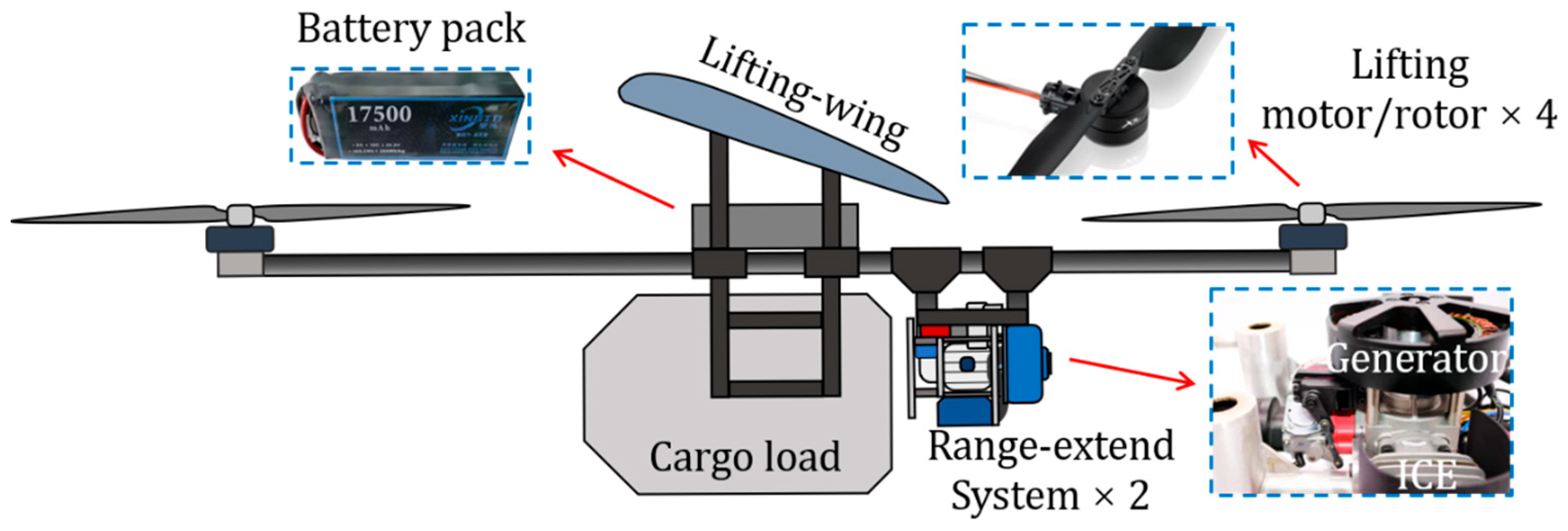
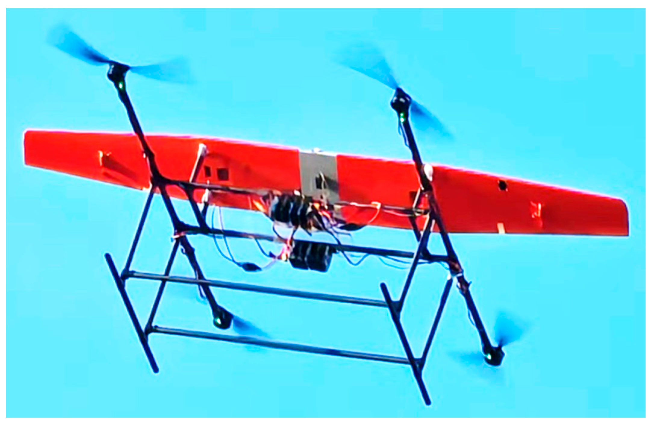
Building on the design of a conventional quadrotor, the proposed fuel–electric range-extended lifting-wing quadrotor seeks to gain additional lift from a pair of wings fixed to its frame, thereby reducing the aerodynamic load on its four rotors. This lifting-wing quadrotor, shown in
Figure 1, offers several advantages rather than those conventional quadrotor aircrafts: first, it consumes less power for its rotors; second, it achieves a longer range and extends the endurance during forward flight; furthermore, compared with compound-wing UAVs and tiltrotor-wing UAVs, the lifting-wing quadrotor has a lighter takeoff weight and a heavier cargo load.
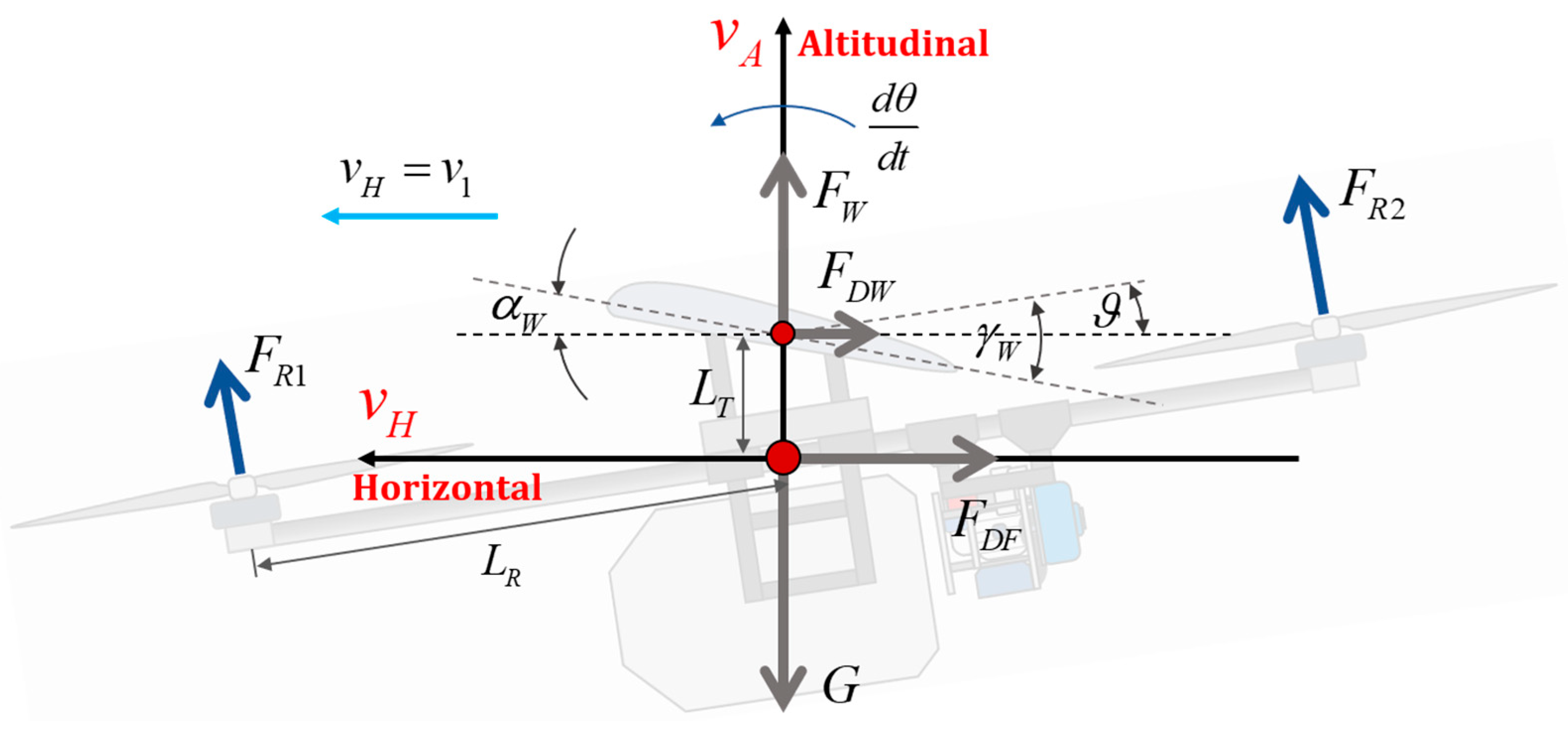
The flight dynamic is established from
Figure 2, where the altitudinal speed is neglected compared to horizontal speed, so that the airflow coordinate system is considered to coincide with the geodetic coordinate system. The flight dynamic is described with balances from horizontal direction, altitudinal direction and pitch angular speed direction, with Equations (1), (2) and (3) respectively.
The lift force and drag force on wings are provided by Equation (5). The lifting wing employs the USA-35B airfoil. The curves of lift and drag varying with angle of attack were fitted based on Profili software V2, as expressed by Equation (4). The lifting wing’s area and the air density are
and
. The regulations of lift coefficient
and drag coefficient
of wing follow the ‘USA-35B’ airfoil. The lift forces
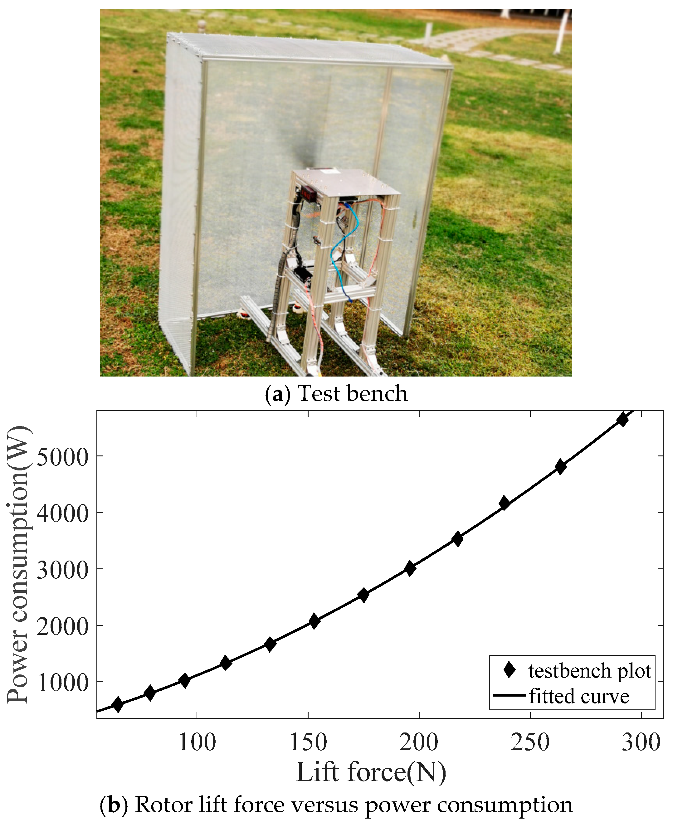
from rotors versus power consumption show a property of quadratic polynomial, that are fitted by testbench and demonstrated in
Figure 3. The lift from rotors are regulated by motor speed regulation signals. The aerodynamic resistance of fuselage is quantified with Equation (6). Some parameters are listed in
Table 1.
The static test bench is utilized to characterize the power consumption of the propulsion system. It consists of a 40 × 13 inch rotor wing and a permanent magnet brushless motor with a 120 mm stator diameter rigidly mounted on a force measurement stand. During the experiment, the motor speed is regulated to collect synchronous data of thrust and power, which is subsequently fitted into the quadratic polynomial curve used for the flight power model.
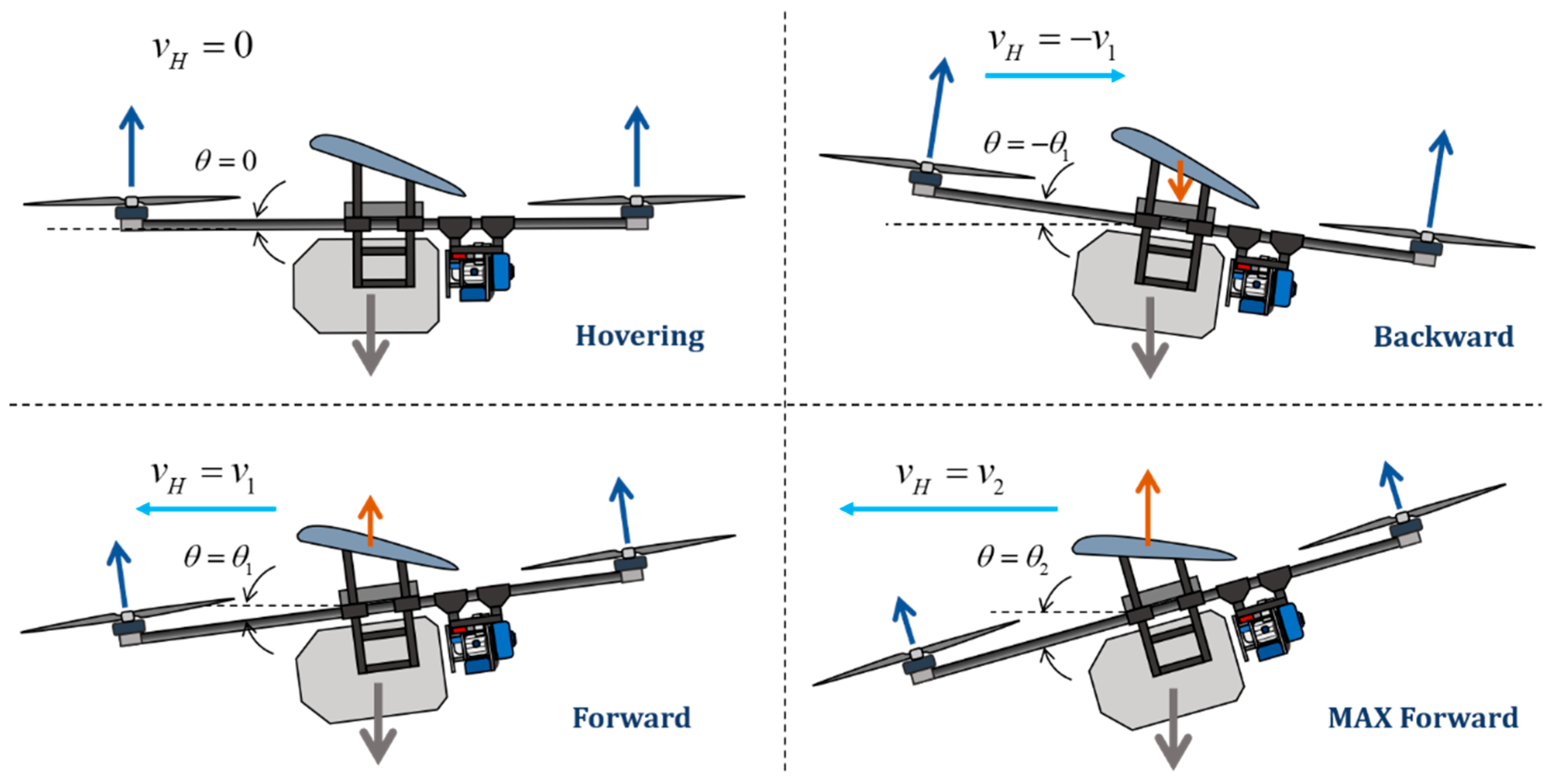
The typical flight phases of this type of UAV, namely vertical take-off and landing, transition flight, and fixed-wing assisted cruise, all center around longitudinal dynamics. During the vertical take-off and landing phase, the power system must output high power to counteract the gravity of the entire aircraft. At this point, the stability of the longitudinal lift directly dictates the power loss of the motor. In the transition flight phase, longitudinal attitude changes such as pitch angle adjustment and airspeed increase will notably modify the wing angle of attack and rotor induced drag, thus influencing the energy consumption efficiency. During the fixed-wing cruise phase, the aerodynamic lift generated by the lifting wing substitutes part of the rotor lift. The matching degree between the longitudinal level flight speed and the wing lift is crucial for reducing cruise energy consumption. In contrast, lateral dynamics, like yaw and roll, are merely used to adjust the flight direction. Their proportion of power consumption is significantly lower than the power demand of longitudinal motion. Therefore, the flight power consumption of the proposed lift-wing quadrotor is primarily determined by its longitudinal flight dynamics, including horizontal flight, vertical flight, and pitching motion, as shown in
Figure 4. In this Figure, the blue arrows depict the thrust direction generated by the rotors, the red arrows correspond to the lift direction of the lifting wings, and the gray arrows represent the gravity acting on the UAV. During constant-altitude flight, the aerodynamic lift generated by the wings, which shares the total gravitational load with the thrust produced by the four rotors, increases positively with airspeed. Consequently, the power consumption decreases as airspeed increases, provided that the pitch angle remains relatively small and the vertical component of force does not undergo a sudden increase. Considering the nonlinear relationship between power consumption and rotor lift, it is highly likely that the overall power consumption will exhibit an accelerating downward trend.
Taking parameters from
Table 1 and the curve from
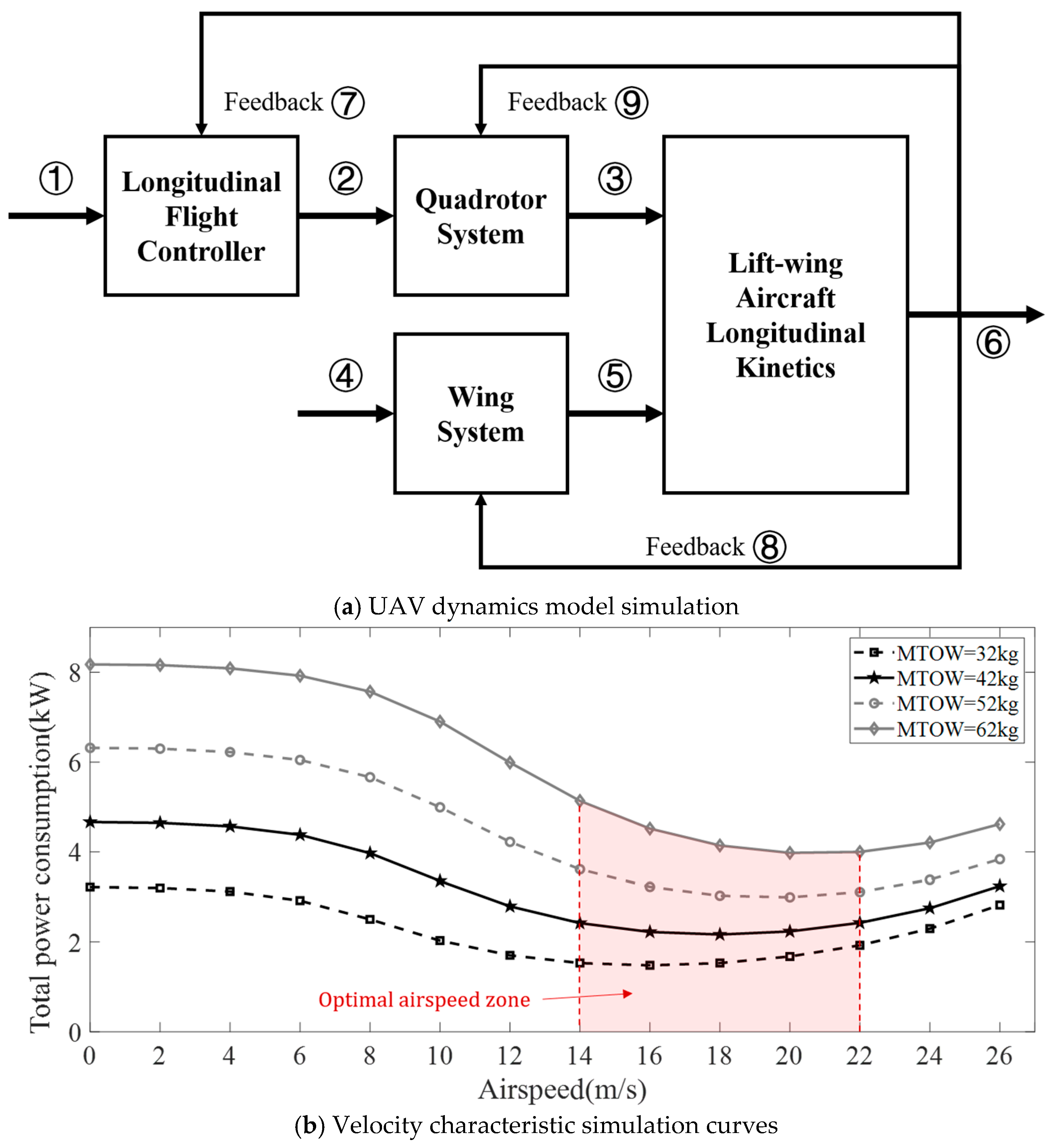
Figure 3, into the longitudinal kinetic flight model of equations from (1) to (6), the simulation results under four different maximum take-off weights (MTOW) are demonstrated in
Figure 5.
In
Figure 5, the total power consumption refers to the sum of the average power consumption of the four quadrotors under different airspeed conditions. Based on the basic mechanism of Equations (1) to (6), rotor power consumption in
Figure 3, and parameters in
Table 1, the steady-state performance of total power consumption with respect to airspeed is simulated, plotted, and curve-fitted in
Figure 5. The result indicates that motor power consumption decreases as airspeed increases, reaching a minimum within an optimal airspeed zone of approximately 14–22 m/s. The power consumption increases beyond a certain airspeed, primarily due to the greater energy required to overcome the rising aerodynamic drag exerted on the fuselage.
Through
Figure 5, it can be inferred that the power consumption throughout the entire logistics flight mission exhibits a distinct peak and valley pattern. Provided that the cruise duration is sufficiently long, the average power consumption will be significantly lower than that of conventional multi-rotor aircraft. Therefore, to reduce takeoff weight, the designed maximum power generation capacity of the onboard RES should be only slightly higher than the cruising power, which is sufficient to achieve peak shaving and valley filling.
The data presented in the original
Figure 5b are derived from a dedicated Simulink-based simulation model, the architecture of which is shown in
Figure 5a. This simulation framework implements the complete control loop of the hybrid power system, including the ECMS energy manager, engine governor, and motor controller.
Table 2 provides a detailed view of the signal assignment at key nodes within the model, where each numeric label corresponds to a specific output signal. These labeled signals enable real-time monitoring and validation of dynamic interactions among subsystems, forming the basis for the performance comparison across control strategies.
3. Optimal Power Supply Strategy
Various power generation and charging strategies are considered when RESs operate during the flight of a lifting-wing quadrotor. At each moment, a RES can be controlled to operate at minimum power, maximum power, or even idle speed, as long as the SOC reaches the target value by the end of the flight mission. Considering costs such as fuel consumption and battery degradation, an optimal control strategy is required to balance the minimization of total cost with power and charging demands.
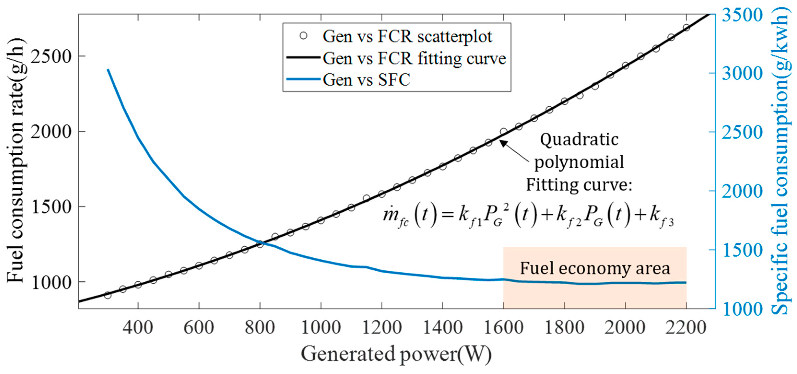
Composed with a single-cylinder gasoline piston engine and a permanent magnet generator, the onboard RES generates DC power through a high-frequency rectifier, paralleling a battery pack. The RES adjusts its generated power output by varying the engine shaft speed and modulating the throttle opening on the fuel regulator of the piston engine, resulting in a fuel consumption rate (FCR) that increases positively with generated power. As shown in
Figure 6, the FCR obtained from the bench test demonstrates an approximate quadratic polynomial relationship with generated power (Equation (7)), whereas the specific fuel consumption (SFC), that considers each unit power, exhibits a monotonically decreasing trend.
The ECMS is a real-time energy management strategy that is widely applied to hybrid power systems. It is particularly valued for its capability to balance dynamic performance and energy efficiency in complex operating scenarios, especially in the demanding field of aviation internal combustion engine applications. In this field, rapid load fluctuations, strict endurance requirements, and limited onboard energy storage capacity present critical challenges. Its core concept is to convert electrical energy consumption or regeneration into an equivalent fuel consumption metric by using a dynamically adjustable equivalence factor. This factor considers the battery’s SOC, current operating conditions, and energy storage characteristics, thus unifying the two distinct energy sources into a single optimization objective. By quantifying battery energy usage, where discharging is counted as positive equivalent fuel consumption and charging as negative or energy recovery as equivalent fuel consumption, the algorithm combines this with the actual fuel consumption of the hybrid system’s internal combustion engine, regardless of whether it serves as a direct power source or a generator for battery charging. Then, it dynamically computes a control scheme that minimizes total energy expenditure in real-time.
In the context of aviation internal combustion engine applications, this is particularly crucial. The ECMS adapts to the variable load demands of different flight phases, such as high-power vertical takeoff, medium-power transition flight, and low-power cruise. It optimally distributes power between the internal combustion engine and the electric propulsion system to avoid inefficient operating regions of the engine, like idling or high-load surges, while keeping the battery SOC within a safe range. The energy management problem investigated in this study can be formulated as an optimal control problem for the onboard hybrid power system of the lifting-wing aircraft. The control objective is to minimize the equivalent fuel consumption over the entire operational cycle, which includes takeoff, transition, cruise, and landing. This should be achieved while satisfying the SOC balance constraint of the battery, ensuring that the battery’s final SOC is consistent with its initial state to maintain cycle life and avoid overcharging or overdischarging. Additionally, other operational constraints, such as power output limits and system response speed must be met.
Based on the principle of energy conservation, a dynamic equilibrium must be maintained between the state of charge variation in the battery and the energy output of the RES, thereby deriving the optimal control objective functional, as Equation (8).
In Equation (8),
means the real-time equivalent fuel consumption of the battery; it is obtained from Equation (9), where
represents a time-varying equivalent factor which can be determined based on the operating conditions of the lifting-wing aircraft to balance the current fuel consumption and the variation in battery SOC.
is the scaling factor,
is the initial equivalent factor, and
is the charging cutoff voltage.
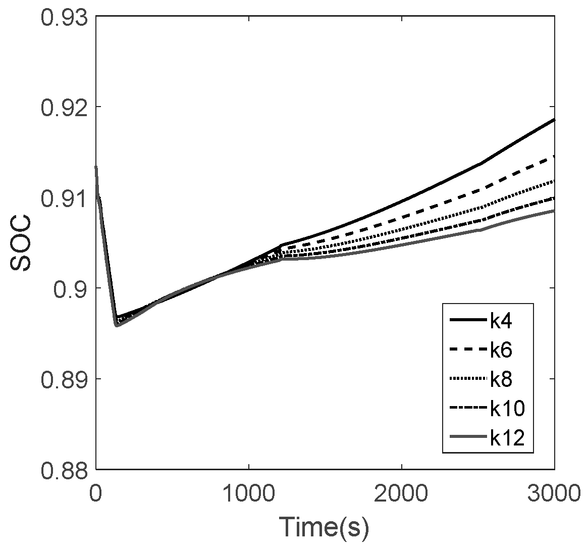
Figure 7 illustrates the simulation results of the State of Charge (SOC) iteration under different values of the adjustment coefficient
(specifically 4, 6, 8, 10, and 12) as defined in Equation (9). This sub-figure demonstrates the impact of the penalty factor on the battery’s energy trajectory. As observed, different
values result in distinct SOC decay rates. A higher
value imposes a stronger penalty on battery energy consumption, leading to a slower decrease in SOC; conversely, a lower
allows for a faster depletion of the battery’s stored energy. The figure shows that when
is set to 10, the SOC trajectory achieves the desired balance, ensuring that the battery maintains an appropriate energy buffer by the end of the mission without over-relying on fuel consumption.
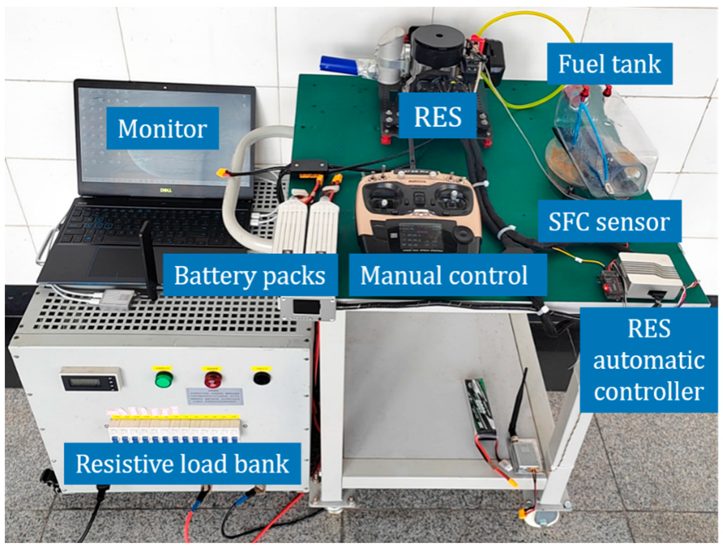
Figure 8 shows the RES test bench, which was used to measure the necessary data for validation. A critical aspect of the ECMS is the tuning of the equivalence factor
, which directly dictates the trade-off between fuel consumption and battery State of Charge (SOC). To address the robustness of our system, we conducted a sensitivity analysis to evaluate the system’s performance under fluctuations of this factor. When the factor deviates from
, the SOC trajectory shifts predictably: a higher factor leads to increased reliance on the engine, preserving battery charge, while a lower factor results in deeper battery discharge. Crucially, even under these fluctuations, the system maintained the SOC within the target bounds (0.85–0.95) throughout the 3000s flight simulation. Furthermore, the total fuel consumption varied by less than 4.5% across all tests. This indicates that while precise tuning optimizes fuel economy, the system remains stable and functional within a reasonable range of parameter error, mitigating the risk of “dimensionality curse” issues often associated with ECMS.
Based on the Ampere-hour integration method, the state equation is expressed as Equation (10), where
is the power required for the current flight scenario, and
is battery capacity.
Therefore, the functional (7) can be rewritten as Equation (11), where the voltage of battery
is regarded as a constant within a short period of time.
The extremum of the functional is obtained as shown in Equation (12). The optimal generated power sequence
is obtained as Equation (13).
To track the optimal generated power sequence, a conventional PID or PI controller is employed to regulate the throttle value of the RES, thereby achieving accurate real-time power generation.
4. Simulation Based on Experimental Results
The kinematic and power consumption model of the lifting-wing aircraft is established based on flight tests of a battery-powered prototype, as shown in
Figure 9.
Experimental flight tests are conducted on the prototype shown in
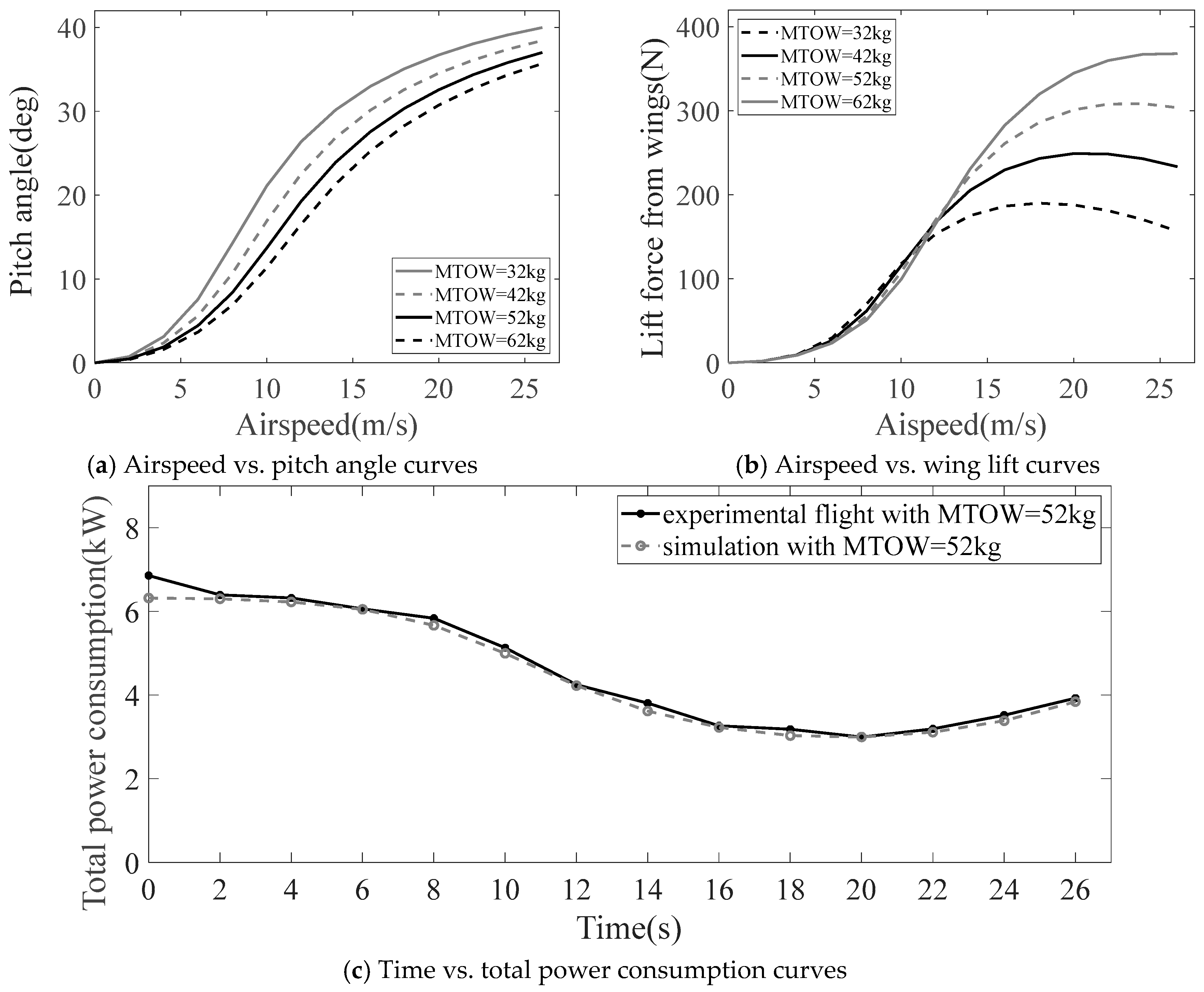
Figure 9, with the MTOW ranging from 32 kg to 62 kg. The steady-state relationships between pitch angle and airspeed, as well as between lift from wings and airspeed, are presented in
Figure 10a and
Figure 10b, respectively. The experimental flight power consumption associated with an MTOW of 52 kg effectively replicated the simulation result in
Figure 6, as shown in
Figure 10c. The effectiveness of the aircraft configuration and flight mechanism was proven, and they were used to conduct the scenario flight simulation described herein.
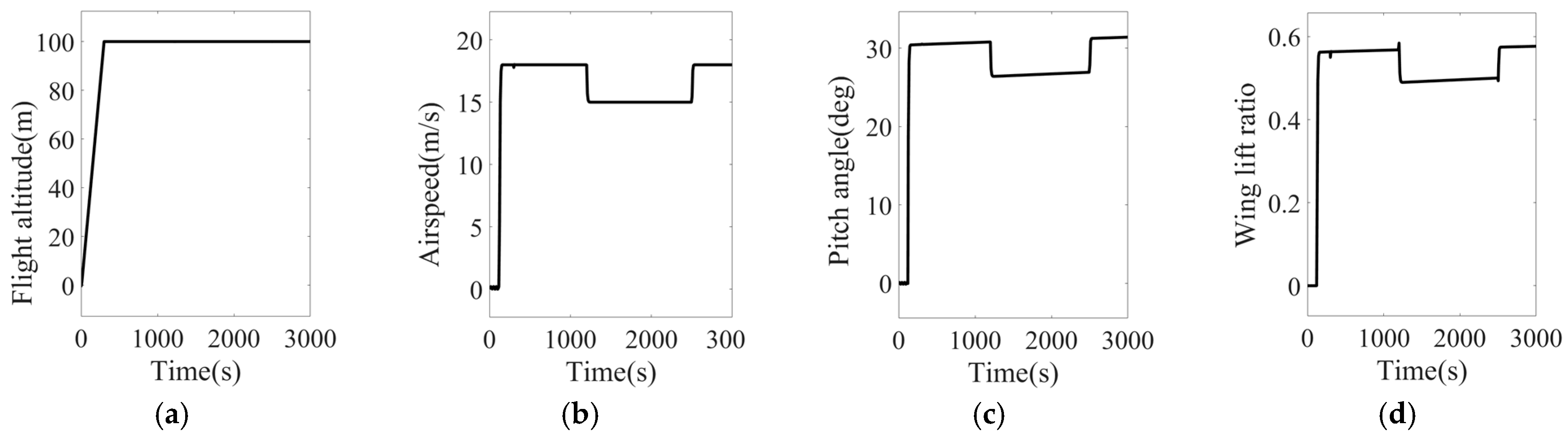
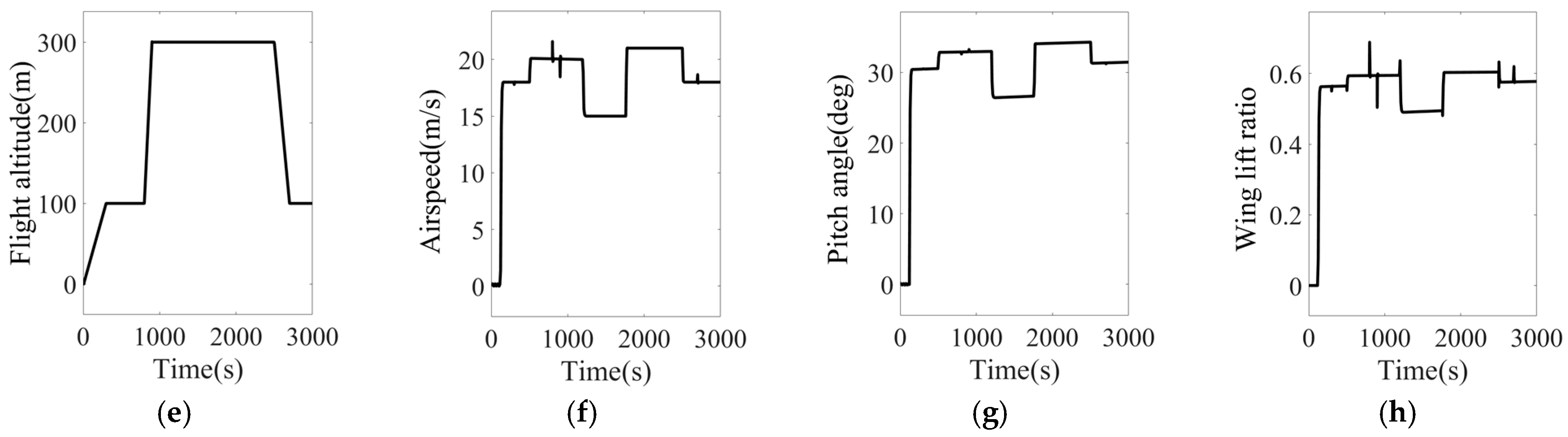
Two typical flight scenarios are simulated in
Figure 10, illustrating airspeed, pitch angle, flight altitude, and wing lift ratio over time.
In Scenario 1, the airspeed varies from 0 m/s to a maximum of 18 m/s, and the flight altitude ranges from 0 m to 100 m, as shown in
Figure 11a and
Figure 11b, respectively. The pitch angle and wing lift ratio are dynamically adjusted according to changes in airspeed, as presented in
Figure 11c,d. Notably, once the airspeed exceeds 15 m/s, the wings provide the majority of the lift. In Scenario 2, which is more severe, the flight altitude ranges from 0 m to 100 m, and the airspeed even exceeds 20 m/s, as shown in
Figure 11e,f. Similarly, the pitch angle and wing lift ratio are shown in
Figure 11g,h. The power consumption of the lifting-wing aircraft is determined and obtained through these flight scenarios.
The parameters of the ECMS are listed in
Table 3, which includes both baseline and reference operating conditions. The maximum power output is capped at 2 kW, and the RES produces no power during idle operation.
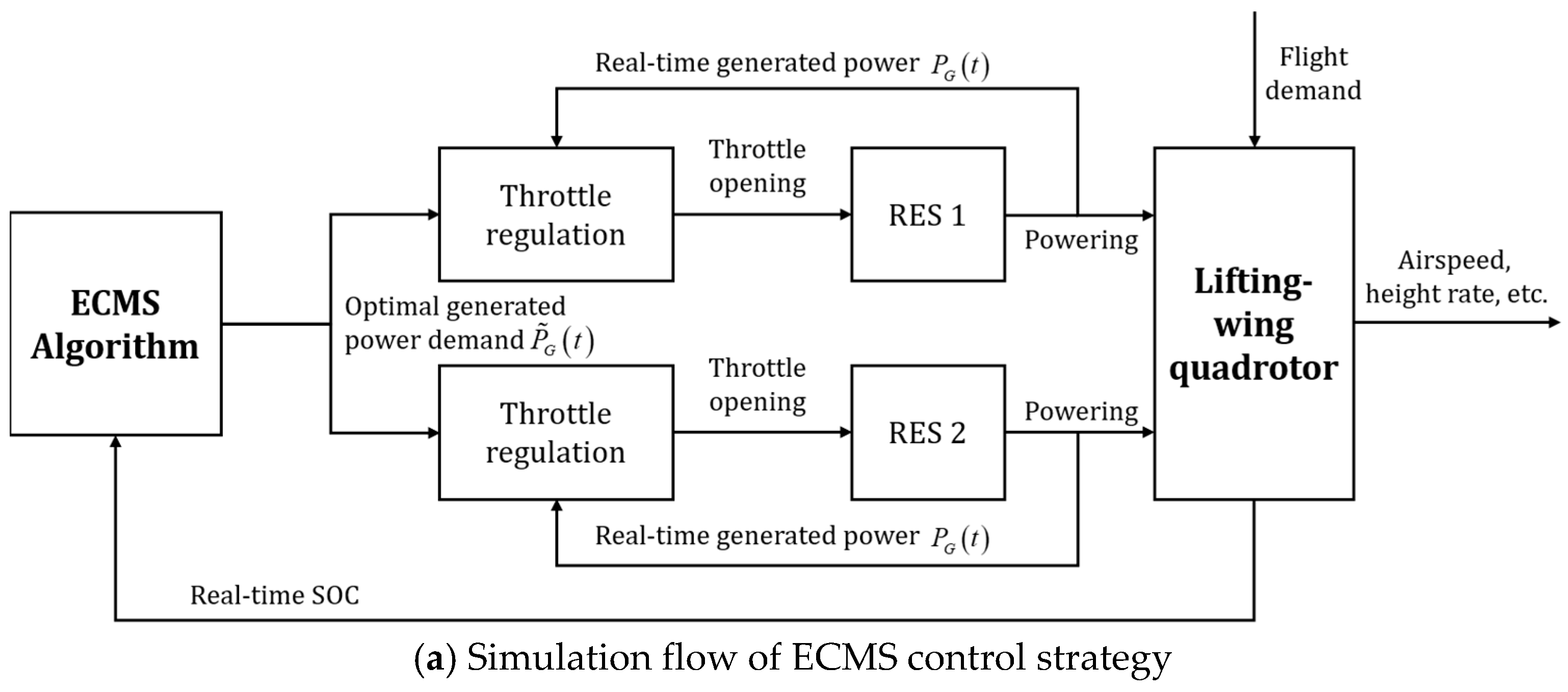
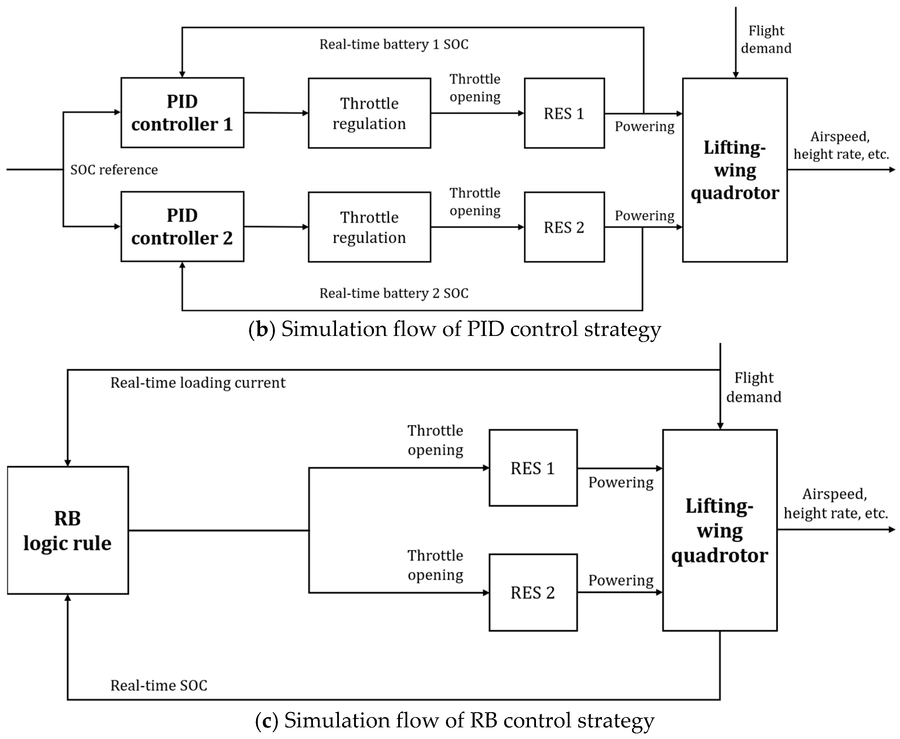
PID controllers are used as a benchmark to further demonstrate the distinct advantages of the proposed strategy. The PID controllers are properly configured and tuned to form closed-loop control of SOC, generating output signals to regulate the throttle opening of RESs, as shown in
Figure 12b.
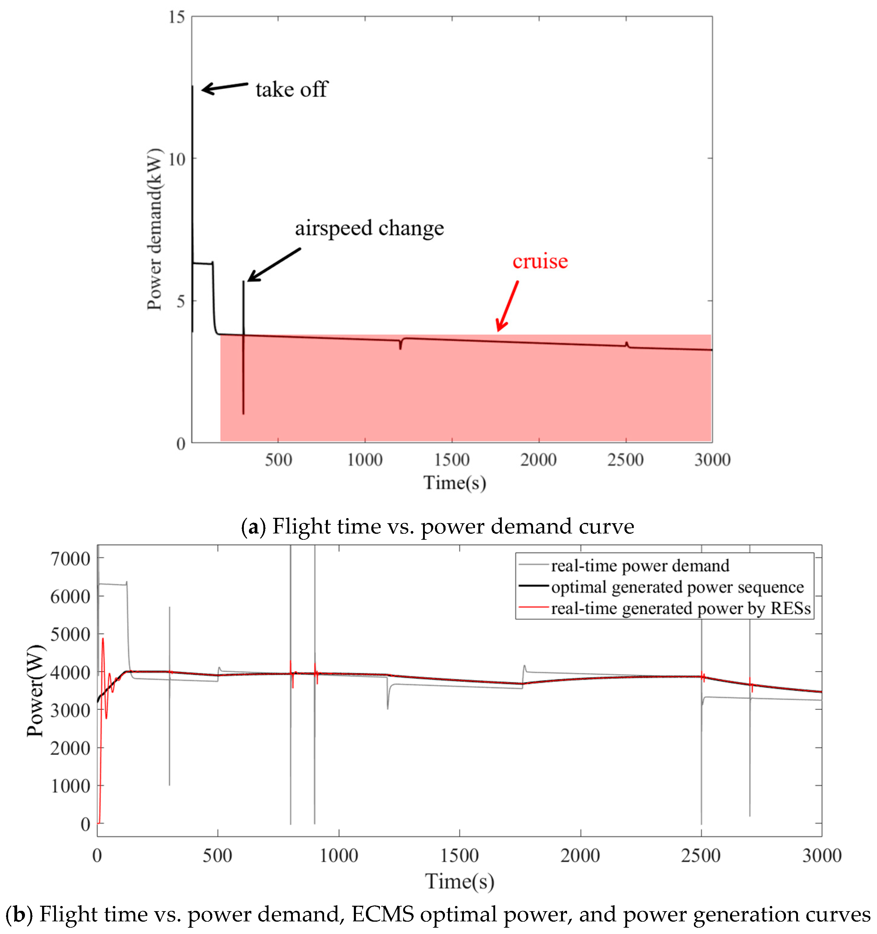
Figure 13a illustrates the real-time power demand curve for Scenario 2. The spikes observed in the graph correspond to abrupt power variations during flight modes or transitions. Since the hybrid system incorporates a battery for energy storage, these transient power peaks have negligible impact on power generation. The real-time power demand of lifting-wing aircraft across the flight scenario is illustrated in
Figure 13b, where the optimal power sequence derived from ECMS is compared with the real-time power generated by RESs. In response to variations in airspeed and altitude, the power demand exhibits significant dynamic fluctuations: the steady-state power ranges from 3 kW to 6.5 kW, with transient peaks reaching up to 10 kW during transitions between flight phases. In contrast, the optimal power sequence generated by ECMS accounts for the overall flight conditions and power requirements, resulting in a considerably smoother curve. Consequently, the real-time power output from RESs is not required to follow abrupt step changes, thereby facilitating fuel savings.
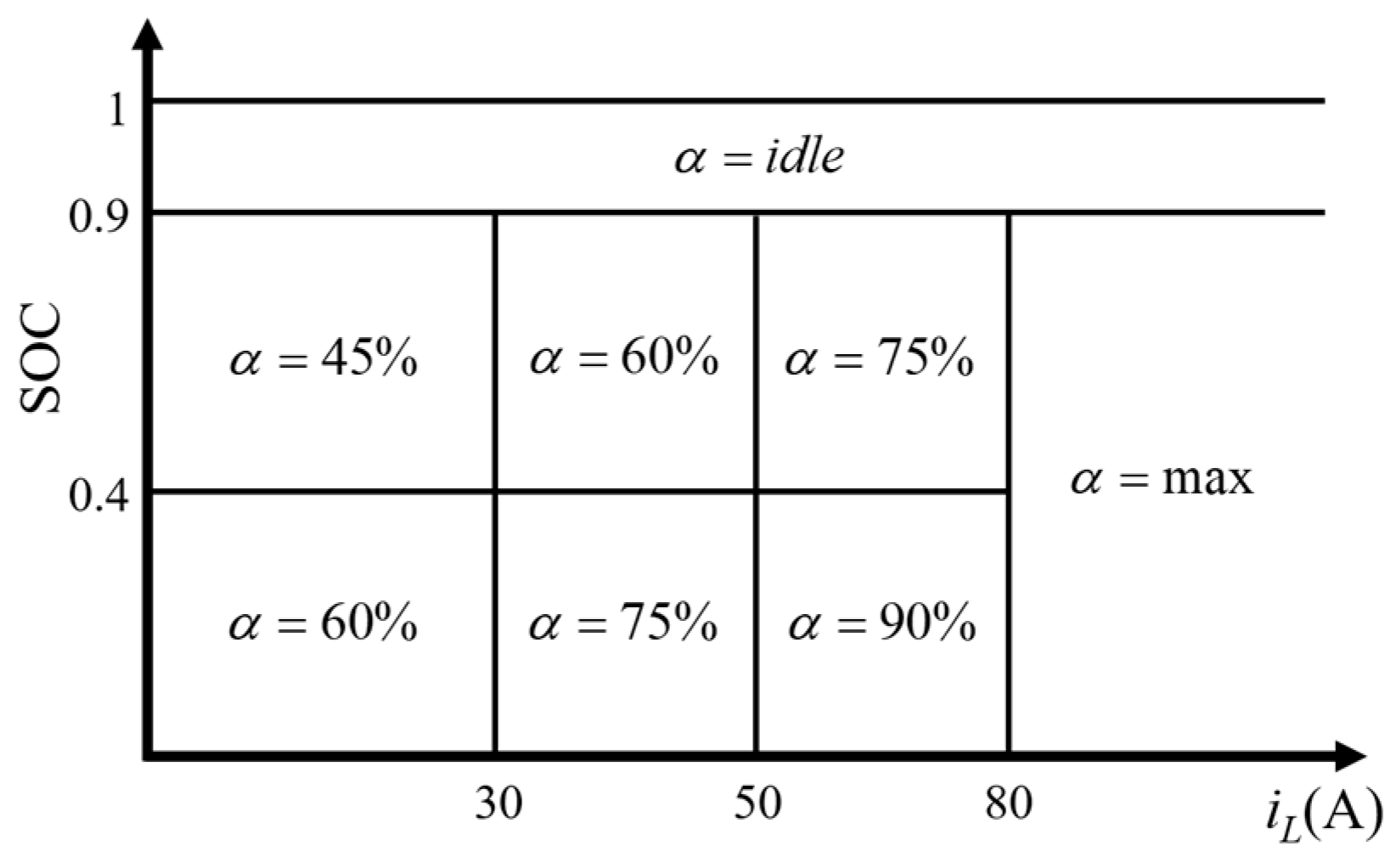
Rule-based (RB) energy management strategies have relatively mature engineering application practices in hybrid vehicles and hybrid aircraft. In terms of technical characteristics, this strategy can achieve energy distribution and coordination of working modes of power sources in a simple and direct way through preset logical rules, and has the advantages of simple control logic, small computational load and strong real-time performance. Therefore, RB strategy is incorporated to enable a more effective comparison with ECMS. In this article, loading current and SOC are the states that directly determine whether the battery is charged and the charging power. Therefore, these two parameters are selected as the logical rules of RB, as illustrated in
Figure 14, and the schematic of RB is shown in
Figure 12c.
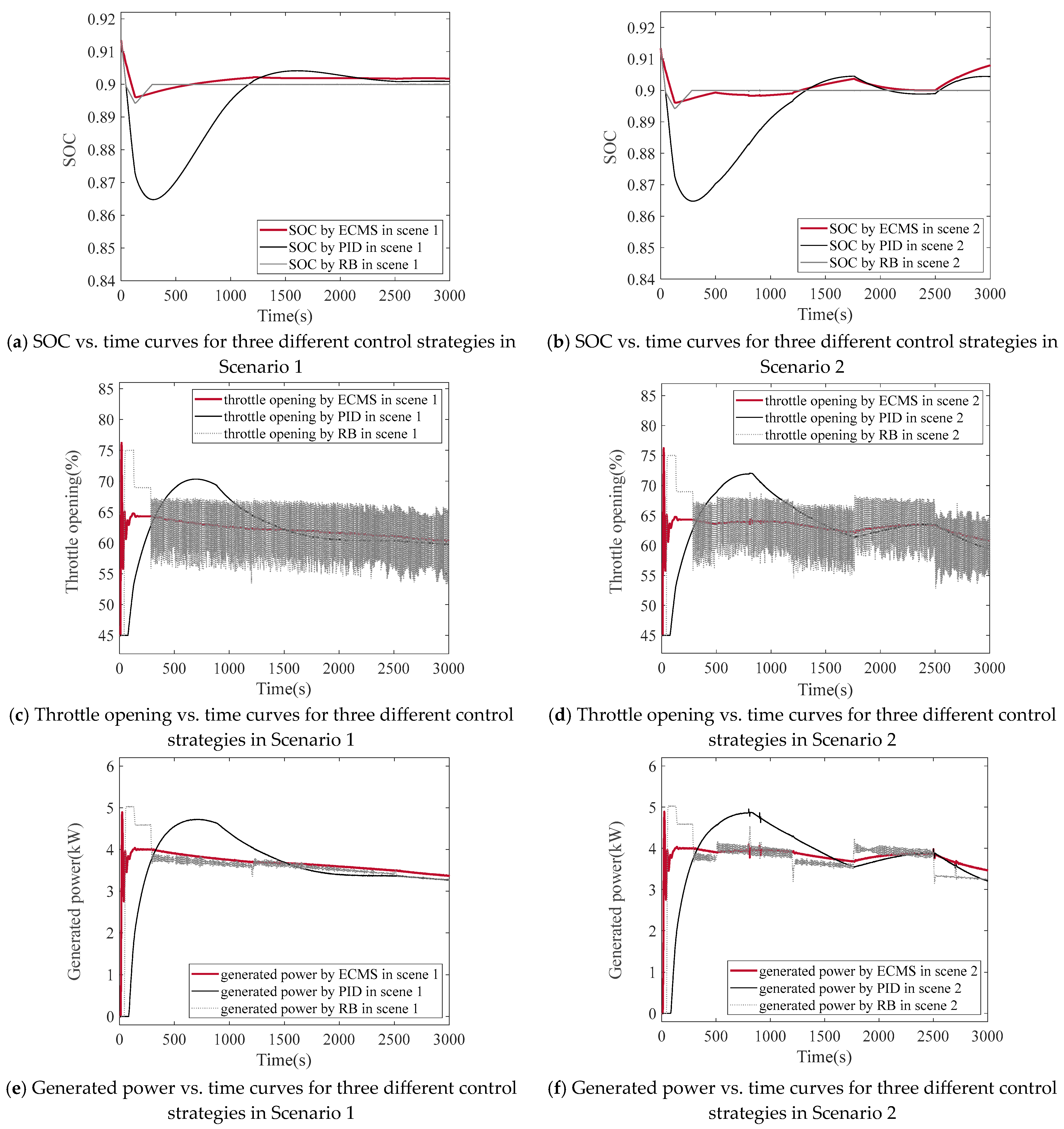
Due to the substantial inertia related to battery capacity, SOC overshoot and response delays are inevitable during flight operations. As depicted in two scenarios
Figure 15a,b, none of these three methodologies can completely prevent the occurrence of overshoot. For the PID controller, the SOC shows a significant initial overshoot, which stands in stark contrast to the smoother SOC trajectory obtained by using the ECMS or RB strategy.
The generated power in two scenarios of three methodologies is shown in
Figure 15e,f. Due to the substantial inertia inherent in battery capacity and the latency in PID control, the generated power exhibits significant fluctuations compared to ECMS and RB, acting in concert with the overhang of the throttle opening in
Figure 15c,d.
From
Figure 15a,b, the RB strategy demonstrates comparable performance with the ECMS in maintaining SOC. Moreover, it even outperforms the latter in terms of steady-state accuracy and overshoot. However, it is important to note that the discretization and fuzziness of the RB rule cause significant fluctuations in the throttle opening, especially near the state boundary, shown in
Figure 15c,d. This, in turn, leads to high-frequency fluctuations in power generation as depicted in
Figure 15e,f. Frequent and substantial adjustments of the throttle valve can cause jamming and failures of mechanical components. Additionally, frequent acceleration and deceleration of ICE can also result in increased fuel consumption and performance degradation.
Throughout the simulations, the performance comparisons in two scenarios among the ECMS, the PID controller and the RB strategy are summarized in
Table 4 and
Table 5. The ECMS achieves lower fuel consumption than the PID controller while maintaining a similar final SOC and the same initial SOC. Notably, the ECMS produces a smoother SOC trajectory with reduced overshoot, indicating diminished battery current fluctuations, thereby contributing to lower battery degradation costs. The RB strategy exhibits the least overshoot and the closest final SOC. However, due to the frequent acceleration and deceleration of the engine, its fuel consumption is significantly higher compared to that of the ECMS.
From the comparisons, ECMS—which is regarded as a strategic-level management method—showed greater proficiency in coordinating diverse energy sources than PID, which is considered more of an operational-level control law. PID increases the generated power when the deviation from the expected value is gradually widening. In contrast to PID and RB, ECMS allocates instructions according to the flight conditions and may adjust the generated power right from the start.
5. Conclusions
This paper presents a comprehensive study on the power management of a novel fuel–electric hybrid range-extended lifting-wing quadrotor UAV. To achieve a considerable range improvement, fixed wings and range-extender systems are integrated into the quadrotor platform, with the research verified through two typical flight scenarios. Key conclusions are summarized as follows.
- (1)
Throughout simulations, partially based on prototype test flight data, the lifting-wing aircraft achieves minimum power consumption within an optimal airspeed range of 15–22 m/s, thereby enabling significantly extended endurance and improved payload capacity compared to conventional multirotor configurations.
- (2)
Range-extender systems are employed to further enhance energy capacity. For more efficient power management, an optimal power distribution strategy based on ECMS has been developed. By converting electrical energy consumption into equivalent fuel consumption, ECMS effectively balances fuel usage and battery utilization, thereby minimizing total energy costs over the course of the flight mission. This strategy ensures smooth power delivery from the RES by tracking an optimized power scenario, reducing abrupt throttle adjustments and improving overall system efficiency.
- (3)
Simulation results, which are validated against experimental data from two typical flight scenarios, demonstrate the superior performance of the equivalent consumption minimization strategy when compared to conventional PID control and the rule-based strategy. In the two flight scenarios, ECMS reduces the total fuel consumption to 4.71 L and 5.02 L respectively, which are lower values than the fuel consumption of the PID controller and RB strategy. Moreover, this strategy maintains a similar initial and final state of charge, along with a smoother state of charge trajectory featuring minimal overshoot, thereby reducing battery degradation costs. RB shows the least state of charge overshoot; however, it leads to higher fuel consumption because of frequent engine speed adjustments. Among the three methods, ECMS achieves the optimal trade-off between fuel efficiency, battery stability, and the operational reliability of mechanical components in both flight scenarios.
Limitations: While the simulation results demonstrate the effectiveness of the ECMS, this study has several limitations that should be acknowledged. First, the current validation predominantly relies on MATLAB R2021a/Simulink simulations based on bench-test data, instead of comprehensive real-world flight tests of the hybrid aircraft. Although the testbench (
Figure 9) provides accurate static characteristics of the RES, the dynamic response of the engine–generator set under actual flight conditions, which are subject to complex aerodynamic loads and vibrations, may deviate from the modeled behavior. The simulation profile (
Figure 11) assumes idealized flight conditions, such as smooth changes in altitude and airspeed, and fails to consider external disturbances like wind gusts or turbulence. These disturbances are common in practical UAV operations and could significantly affect the power demand and SOC tracking performance. Moreover, the study mainly focuses on a specific longitudinal flight profile. The performance of the ECMS in more complex three-dimensional maneuvering flight or emergency scenarios has not been thoroughly evaluated. Future work will aim to address these gaps through hardware-in-the-loop testing and actual flight validation.
Practical Implications for Design and Operation: Beyond the theoretical validation, this study offers concrete guidance for the engineering design and operational deployment of hybrid UAVs.
For Energy System Design: The findings regarding the “optimal airspeed zone” (14–22 m/s) and the power demand characteristics provide a scientific basis for Range-Extended System (RES) sizing. Our results indicate that the maximum power generation capacity of the RES only needs to be slightly higher than the cruising power (approximately 3–4 kW for this configuration, as shown in
Figure 14). This “peak shaving and valley filling” strategy allows designers to select smaller, lighter generators, thereby increasing the payload fraction and overall efficiency of the aircraft.
For Operational Deployment: The ECMS demonstrates a superior trade-off between fuel economy and battery health. By maintaining a smoother State of Charge (SOC) trajectory and reducing frequent throttle adjustments, the proposed strategy directly contributes to reduced operational costs. It minimizes fuel consumption during missions while mitigating battery degradation, which lowers the long-term maintenance and replacement costs of the power system. Furthermore, the methodology provides a reference for operators to plan flight profiles within the optimal airspeed range to maximize endurance.




 ,
,