1. Introduction
The miniaturization of actuators for applications that need large displacements, high energy efficiency or output forces is an ongoing challenge [
1]. Piezoelectric ultrasonic motors (USM) have proven to be a suitable solution to obtain long motion range, high torque, quick response, high power to weight ratio and high efficiency in comparison to electrostatic, magnetic, and thermal alternatives [
2,
3,
4]. Despite the advantages of USM for linear motion, scaling down to the millimetre range remains a challenge due to the difficulties in generating standing or travelling waves at high frequencies with enough amplitude [
5].
In pursuit of miniaturization, the monolithic fabrication based on silicon micromachining was successfully applied to the effective size reduction of such positional devices. Different actuation techniques have benefited from Micro-electromechanical Systems (MEMS) technology, demonstrating locomotion or conveyance on the millimetre scale with speeds of a few millimetres per seconds and payloads below 50 mg [
6,
7,
8]. However, to reach a step further into the miniaturisation of efficient motors, piezoelectric actuation becomes a promising alternative [
9,
10].
In this work, we present a hybrid design for linear locomotion based on piezoelectric MEMS resonators with 3D-printed legs. The MEMS-based resonator consists of a conductive silicon bridge, actuated thanks to an integrated aluminium-nitride (AlN) piezoelectric film sandwiched between the silicon film and the metallic electrodes. Analytical approaches were used to calculate the optimal electrode layout for the efficient generation of the mechanical waves, i.e., standing wave or travelling wave, in the motor. The movement of the surface of the silicon plate was transferred to a slider through an array of 3D-printed legs attached to its surface, allowing controlled contact between the stator and slider and the amplification of elliptical or diagonal movement caused by the travelling wave (TW) or the standing wave (SW), respectively. The conveyance of light sliders was demonstrated, and the kinetic capabilities of the motor were characterised under both operation modes.
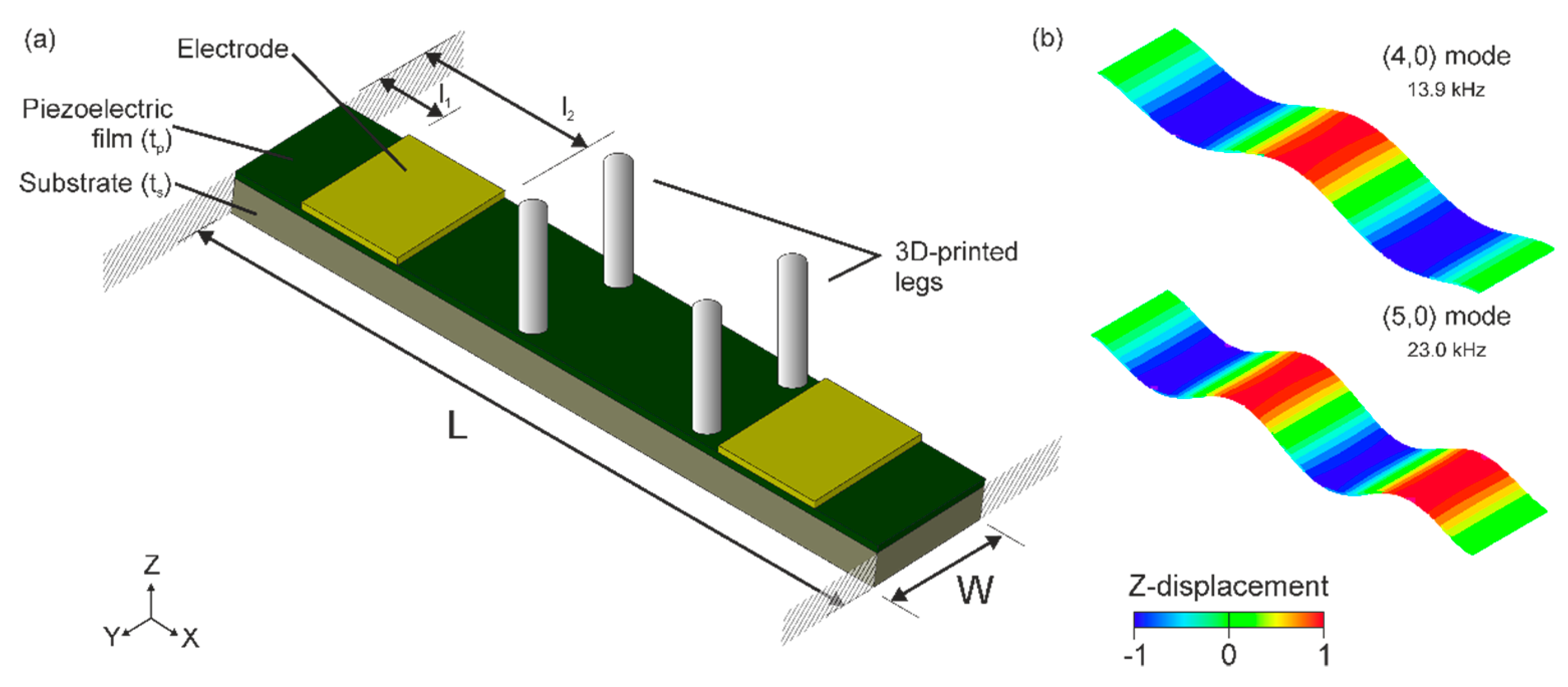
2. Device Design
Here, we focus on the linear motors based on piezoelectrically actuated bridges with a length
and a width
. The structure consisted of a silicon substrate with a thickness
, an aluminium-nitride (AlN) piezoelectric film with a thickness
and two 500-nm thick Gold (Au) electrode patches on top, that were neglected in the mechanical analysis.
Figure 1a depicts the layout.
The generation of bidirectional linear motion would rely on the flexural vibration modes of the bridge structure in
Figure 1a. In particular, the third- and fourth-order bending modes, i.e., (4,0) and (5,0) modes using Leissa nomenclature [
11].
Figure 1b shows the modal shapes and their respective resonant frequencies.
The actuation principle of the motor is based on the generation of mechanical waves—either standing wave (SW) or travelling wave (TW) types—on the piezoelectrically actuated structure, together with the inclusion of 3D-printed millimetre long legs. These legs will ensure the contact between the vibrating structure and the stator while transmitting a translational motion to the slider.
The generation of linear TW in beams by the combination of two flexural vibration modes was already reported using two symmetrically placed piezoelectric patches [
10]. Here, we followed the same approach, obtaining the patch position and size that optimises the TW quality and amplitude with the targeted modes in
Figure 1b. Regarding leg position, those should be placed where the TW envelope is ideally constant to ensure an elliptical trajectory at the tip [
12]. That condition is met at the central plateau of the TW envelope, the area between the two patches [
10].
Linear motion can also be obtained by inducing an SW in the resonator and by choosing an appropriate distribution of legs [
13]. A stiff leg placed between a node and a peak of the modal shape wave (
Figure 1b) would describe a diagonal trajectory. Depending on the chosen side of the crest, the thrust exerted to the rotor would be in the positive or negative directions of the wavelength. Therefore, to achieve bidirectional motion, two different flexural modes can be used. By placing the legs at any of the intersecting regions between the chosen side crests for each mode, the same device could be used as an SW motor, with two different directions of movement depending on the vibration mode excited.
According to Reference [
10], the optimal patches for TW generation could be suitable for SW generation too. Besides, in order to maximize excitation of the SW and taking advantage of the two-patch configuration, a phase optimisation was performed [
14]. Finally, the combination of this patch design together with attached legs in the intersecting crests regions (SW operation mode) within the central plateau (TW operation mode) would allow the same motor to be operated under SW or TW conditions.
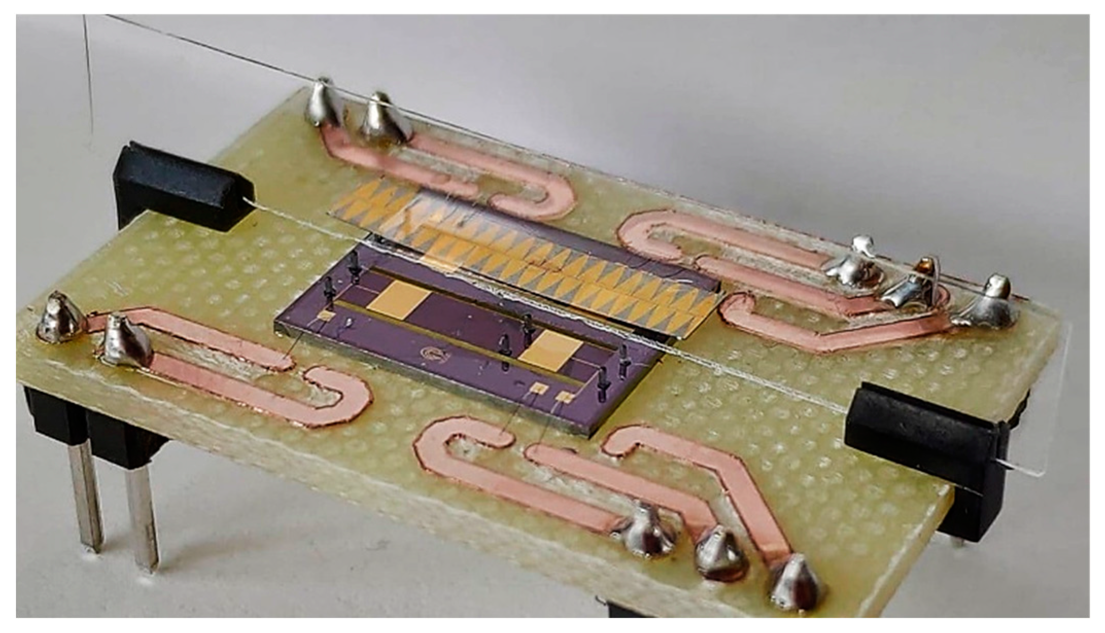
3. Materials and Methods
Monolithic microfabrication techniques were used to implement rectangular microplates according to the geometry and materials previously described, clamped at both sides. For all devices, the layer structure was as follows: a 30-μm thick, p-doped (100), silicon plate served as the bottom electrode, which was covered with a 1-μm thick AlN piezoelectric film. As the top electrode, 500-nm thick Au electrodes were deposited. Dices with two different devices were glued and wire-bonded to a printed circuit board (PCB) to facilitate electrical access (
Figure 2).
Cylindrical legs with a length of 750 µm and a diameter of 300 µm were designed and manufactured using a B9 Core 530 DLP 3D printer, using proprietary black resin. The active pair of legs was glued on the bridge surface using a cyanoacrylate-based adhesive (see
Figure 2), and two additional pairs were placed at the device frame, serving as passive supports.
In the kinetic characterization, a Tektronix AFG 3000 series arbitrary waveform generator (AWG) was used to generate the required waveforms to be applied to each of the electrode patches. In the experimental setup, the PCB containing a pair of such devices (see
Figure 2) was placed on a levelled platform in order to avoid an uneven movement of the slider under the microscope camera. The orthogonal movement of the sliders was restricted to a rectilinear lane with the help of glass pieces. The movement of the slider was optically recorded by a microscope camera, and the videos were processed by a motion tracking algorithm programmed in MATLAB in order to obtain the slider positions versus time. The mean speed was computed afterwards.
4. Results
The application of the motor to transport objects in contact with the device surface was assessed in the two operation modes, with sliders consisting of silicon plates of 15 × 3 × 0.02 mm3 with a mass of 2 mg. In the TW operation mode, the motor was actuated at 19.55 kHz with 90° for the forward direction and −90° for the reverse direction. In the SW operation mode, the motor was actuated in the (4,0) mode at 15.25 kHz with no phase difference between patches for the reverse direction and in the (5,0) mode at 24 kHz with a phase difference of 180° for the forward direction.
Figure 3 shows the results from the kinetic characterization in the forward direction (similar results were obtained in the reverse direction). As it can be seen, in the TW operation mode, the motor was able to develop conveyor speeds of 1.2 mm/s at 10 V, while in the SW operation mode, the speed reached a maximum value of 27 mm/s. This speed of almost 3 BL/s (body-lengths per second) supposes a huge improvement compared to the TW operation mode, mainly due to the actuation of the motor in resonance.
Besides, the minimum excitation to generate locomotion of the slider was as low as 2 V in the SW operation mode, with a linear dependence of the speed with the applied voltage up to 4 V when a speed of 20 mm/s was reached. From them, a decrease in the growth rate of the speed with voltage was found, which can be attributed to the low inertia of the light slider used in the tests.
5. Conclusions
This work reports the design, fabrication, and electrical and optical characterization of piezoelectric MEMS plates for linear motion applications. Successful generation of bidirectional TW was demonstrated on a monolithic microfabricated silicon-based bridge combined with 3D-printed legs to overcome the intrinsic limitation of the suspended bridge to attain an efficient contact with objects. The bridge devices were also excited in resonance, inducing SW based on the third and fourth flexural modes. The 3D-printed legs were placed at those positions in which the resonator could act as a bidirectional resonant motor.
The kinetic performance of the fabricated motor was studied with a 2-mg slider. The conveyor demonstrated bidirectional speeds of 1.2 mm/s when a TW was induced in the resonator at 10 V and a frequency of 19.55 kHz. The same device could be operated in resonance by inducing SWs based on the (4,0) and (5,0) modes at 15.25 and 24 kHz. In this operation mode, the conveyor demonstrated speeds as high as 27 mm/s for continuous sinusoidal excitation.
Author Contributions
Conceptualization, J.L.S.-R.; software, V.R.-D.; investigation, V.R-D.; writing—original draft preparation, V.R.-D.; writing—review and editing, J.L.S-R. and J.H.-G.; supervision, J.L.S.-R. and J.H.-G.; project administration, J.L.S.-R. and J.H.-G.; funding acquisition, J.L.S.-R. and J.H.-G. All authors have read and agreed to the published version of the manuscript.
Acknowledgments
This work was supported by the European Regional Development Fund, the Spanish Ministerio de Ciencia, Innovación y Tecnología project (RTI2018-094960-B-100) and by the regional government (JCCLM) project (SBPLY/17/180501/000139).
Conflicts of Interest
The authors declare no conflict of interest.
References
- Uchino, K. MicroMechatronics, 2nd ed.; CRC Press: Boca Raton, FL, USA, 2019. [Google Scholar]
- Chan, M.L.; Yoxall, B.; Park, H.; Kang, Z.; Izyumin, I.; Chou, J.; Megens, M.M.; Wu, M.C.; Boser, B.E.; Horsley, D.A. Design and characterization of MEMS micromotor supported on low friction liquid bearing. Sens. Actuators Phys. 2012, 177, 1–9. [Google Scholar] [CrossRef]
- Khiat, A.; Spronck, J.W.; van Schieveen, J.; Milosavljevic, S.; Wei, J.; Estevez, P.; Sarro, P.M.; Staufer, U. Linear and rotational thermal micro-stepper motors. Microelectron. Eng. 2012, 98, 497–501. [Google Scholar] [CrossRef]
- Sarajlic, E.; Yamahata, C.; Cordero, M.; Fujita, H. Three-Phase Electrostatic Rotary Stepper Micromotor with a Flexural Pivot Bearing. J. Microelectromechanical Syst. 2010, 19, 338–349. [Google Scholar] [CrossRef]
- Pulskamp, J.S.; Polcawich, R.G.; Rudy, R.Q.; Bedair, S.S.; Proie, R.M.; Ivanov, T.; Smith, G.L. Piezoelectric PZT MEMS technologies for small-scale robotics and RF applications. MRS Bull. 2012, 37, 1062–1070. [Google Scholar] [CrossRef]
- Kladitis, P.E.; Bright, V.M. Prototype microrobots for micro-positioning and micro-unmanned vehicles. Sens. Actuators Phys. 2000, 80, 132–137. [Google Scholar] [CrossRef]
- Ebefors, T.; Mattsson, J.U.; Kälvesten, E.; Stemme, G. A walking silicon micro-robot. In Proceedings of the 10th International Conference on Solid-State Sensors and Actuators, Transducers’99, Sendai, Japan, 7–10 June 1999; pp. 1202–1205. [Google Scholar]
- Yahiaoui, R.; Zeggari, R.; Malapert, J.; Manceau, J.-F. A MEMS-based pneumatic micro-conveyor for planar micromanipulation. Mechatronics 2012, 22, 515–521. [Google Scholar] [CrossRef]
- Smith, G.L.; Rudy, R.Q.; Polcawich, R.G.; DeVoe, D.L. Integrated thin-film piezoelectric traveling wave ultrasonic motors. Sens. Actuators Phys. 2012, 188, 305–311. [Google Scholar] [CrossRef]
- Ruiz-Díez, V.; Hernando-García, J.; Toledo, J.; Ababneh, A.; Seidel, H.; Sánchez-Rojas, J.L. Bidirectional Linear Motion by Travelling Waves on Legged Piezoelectric Microfabricated Plates. Micromachines 2020, 11, 517. [Google Scholar] [CrossRef] [PubMed]
- Leissa, A.W.; Qatu, M.S. Vibration of Continuous Systems; McGraw Hill Professional: New York, NY, USA, 2011; ISBN 9780071714808. [Google Scholar]
- Hernando-García, J.; García-Caraballo, J.L.; Ruiz-Díez, V.; Sánchez-Rojas, J.L. Motion of a Legged Bidirectional Miniature Piezoelectric Robot Based on Traveling Wave Generation. Micromachines 2020, 11, 321. [Google Scholar] [CrossRef] [PubMed]
- Siyuan He; Weishan Chen; Xie Tao; Zaili Chen Standing wave bi-directional linearly moving ultrasonic motor. IEEE Trans. Ultrason. Ferroelectr. Freq. Control 1998, 45, 1133–1139. [CrossRef] [PubMed]
- Ruiz-Díez, V.; Manzaneque, T.; Hernando-García, J.; Ababneh, A.; Kucera, M.; Schmid, U.; Seidel, H.; Sánchez-Rojas, J.L. Design and characterization of AlN-based in-plane microplate resonators. J. Micromech. Microeng. 2013, 23, 074003. [Google Scholar] [CrossRef]
| Publisher’s Note: MDPI stays neutral with regard to jurisdictional claims in published maps and institutional affiliations. |
© 2020 by the authors. Licensee MDPI, Basel, Switzerland. This article is an open access article distributed under the terms and conditions of the Creative Commons Attribution (CC BY) license (https://creativecommons.org/licenses/by/4.0/).


