1. Introduction
Shape memory alloy (SMA) actuators including the commonly used SMA wires are already present in a few commercially available products. The company Actuator Solutions GmbH, for example, offers a variety of different gas and fluid valves as well as camera systems based on SMA wire actuators [
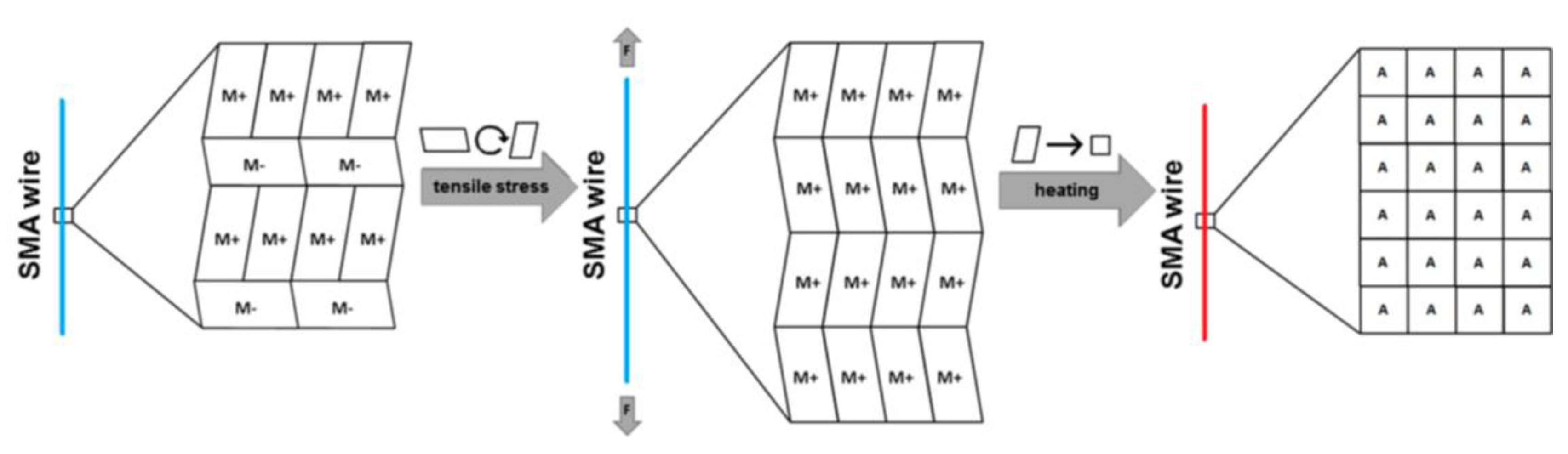
1]. SMA actuator wires will contract when heated, in technical applications, typically via an applied current. The contraction is a consequence of a phase transformation (
Figure 1) between martensite (cooled wire) and austenite (heated wire) [
2,
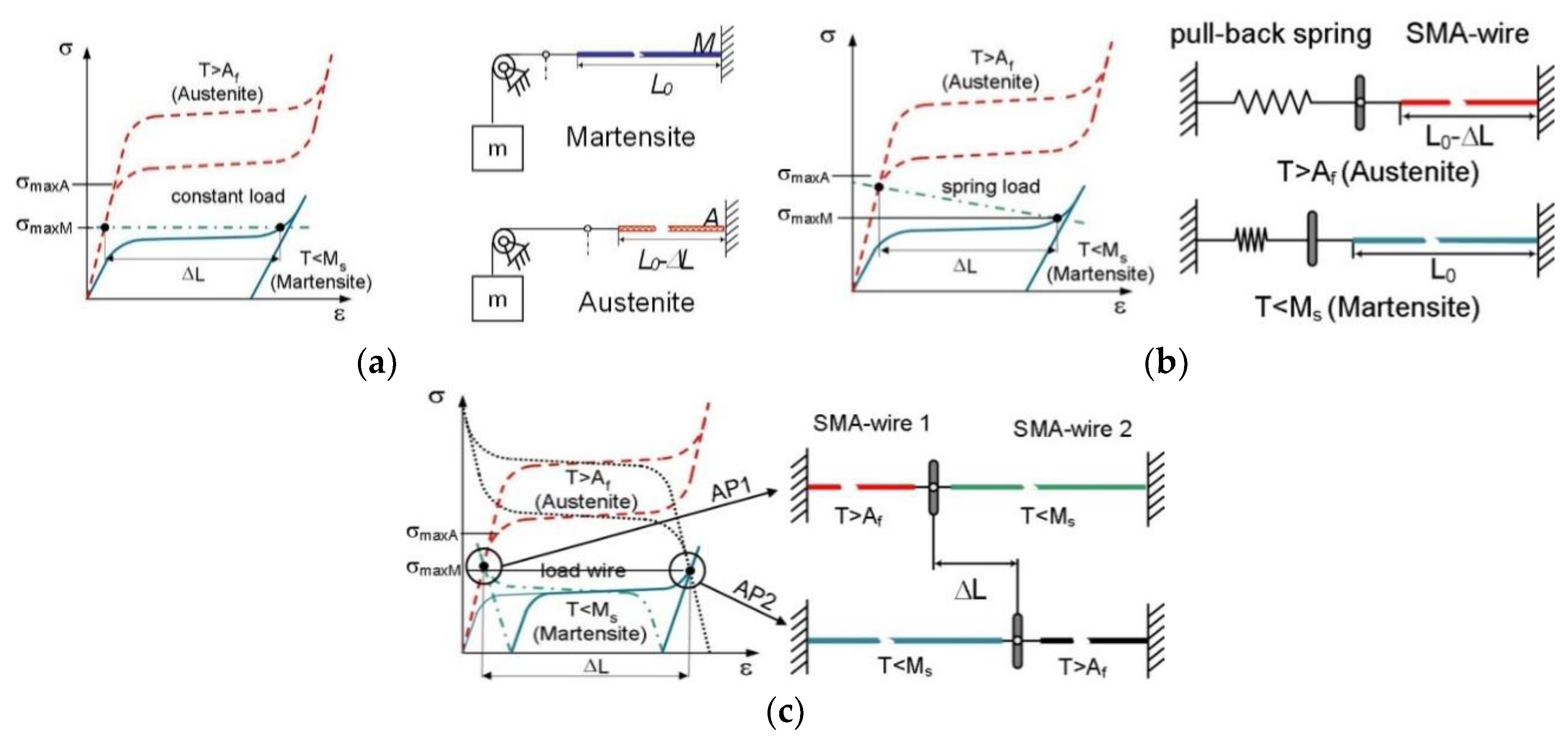
3]. In order to return to the extended length, the wires are coupled with an additional biasing mechanism (
Figure 2), such as the gravitational force of a mass (a), a restoring coil spring (b), or the pulling force of a second SMA actuator (c) [
4]. One drawback of an SMA actuator wire system, such as when coupled with a constant force or a coil spring, is the continuous energy needed to remain in the activated position [
5,
6,
7,
8]. The bias force keeps the not-activated SMA wire in a defined initial position. Activation and contraction of the SMA wire causes the SMA actuator to reach a second position. To remain in this second position, the SMA wire has to be constantly heated, resulting in continuous energy consumption. Moreover, a position or power control is necessary to keep the actuator in this defined second position, independently of environmental influences such as temperature changes or increased convective cooling through higher air flow rates [
9,
10]. The actuation stroke of the SMA wire is dependent on its length (typically around 4% max [
11,
12]). To produce large strokes, SMA actuators often need large construction space. The pulling force, as well as actuation cycling speed, is directly dictated by the diameter of the SMA wires [
13,
14].
To address the drawbacks mentioned above, a new SMA actuator design is presented. In this actuator, a bi-stable snapping mechanism is combined with an antagonistic SMA wire configuration. In this way, the actuator has two defined stable and energy-free positions. The SMA wires are only activated to switch between these two positions. The force output and the stroke of this actuator are only dependent on the snap design, rather than being directly linked to the SMA wires’ lengths and diameters. This allows for the construction and the design of very compact and energy-efficient actuators. Additionally, the actuation frequencies are increased, because the antagonistic configuration provides active actuation in both directions, unlike in an SMA–spring combination.
Another way to improve the energy efficiency of SMA actuators is through electrical control concepts. In current state-of-the-art actuators, the SMA wire activation takes place under non-adiabatic conditions, i.e., a large amount of the heating energy is lost due to heat exchange with the environment during the activation process. With high electrical power and a fast heating pulse, it is possible to reach the transformation temperature and start actuation before heat is lost to the environment, thus leading to adiabatic activation [
16]. This control concept can also be used for typical mains AC voltages and leads to energy savings of up to 80% in comparison to the traditional quasi-static activation of SMA wire actuators [
17].
Following this introduction, the design of the bi-stable SMA actuation mechanism is presented in the first main chapter. The advantages of this innovative actuator design are illustrated through the example of the application of an industrial vacuum gripping system. The subsequent second main chapter introduces energy-efficient high voltage activation concepts. Systematic experimental studies are used to quantify energy savings. The paper is concluded by a short summary of the presented results.
2. Bi-Stable SMA Actuator Design Concept
The core item in this energy-efficient actuator design is the bi-stable element. For the first studies, a thin beam out of sheet metal is used, but the actuator is not limited to this material or geometry [
18]. The key to this new actuator design is the pivot-mounting of the bi-stable element.
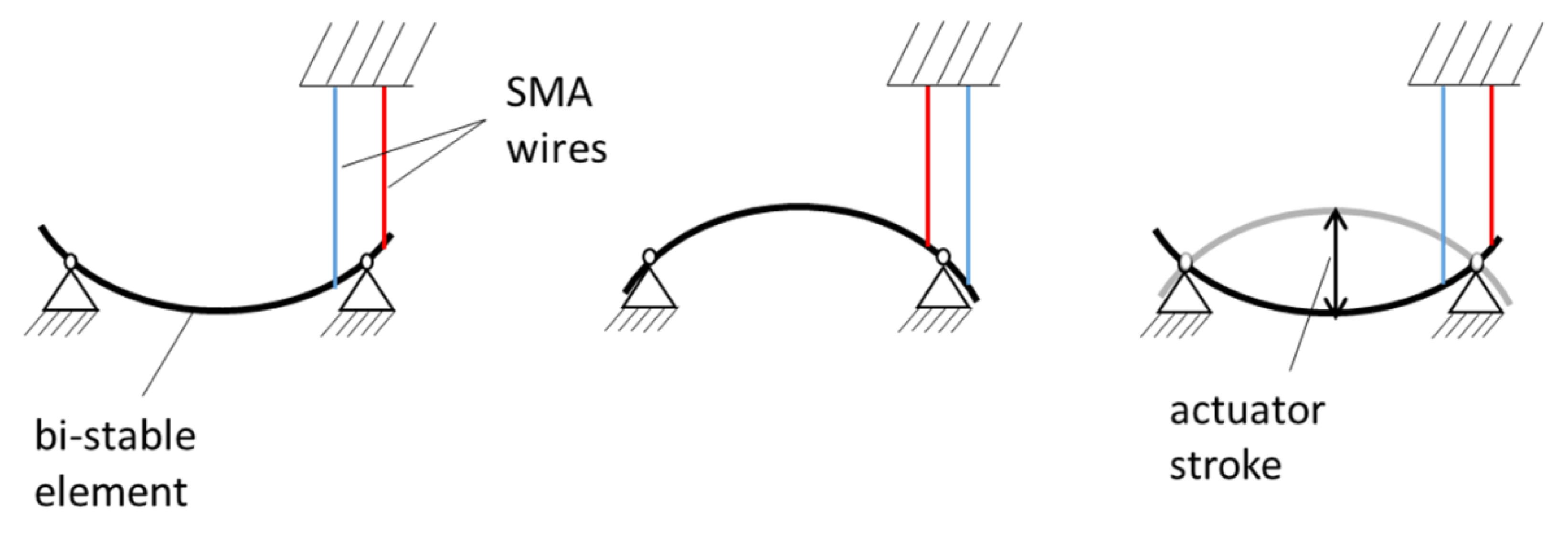
Figure 3 shows a basic combination of the bi-stable element and SMA wires and explains the actuator function principle.
In this example, the bi-stable element is mounted with two pivot joints. On each side of one of the joints, an SMA wire is attached. In this antagonistic configuration, the bi-stable element snaps into its second position whenever one of the SMA wires is activated. The maximum actuation stroke is observed in the center of the beam and depends on its pre-bending. The minimum length of the SMA wires depends on their attachment point. The more closely they are attached to the pivot point, the less SMA wire stroke is needed to induce a snapping of the beam. At the same time, more SMA force will be needed for closer attachment points, but SMA force can easily be scaled with a larger wire diameter or the addition of more wires in a parallel mechanical configuration.
Using the bi-stable mechanism as a transmission element to convert the high energy density of the SMA wires into large strokes, the design space of the actuator can be reduced. The bi-stable actuator mechanism enables the design of high-performance actuation systems with high stroke, high activation frequency, small design space and high energy efficiency [
19].
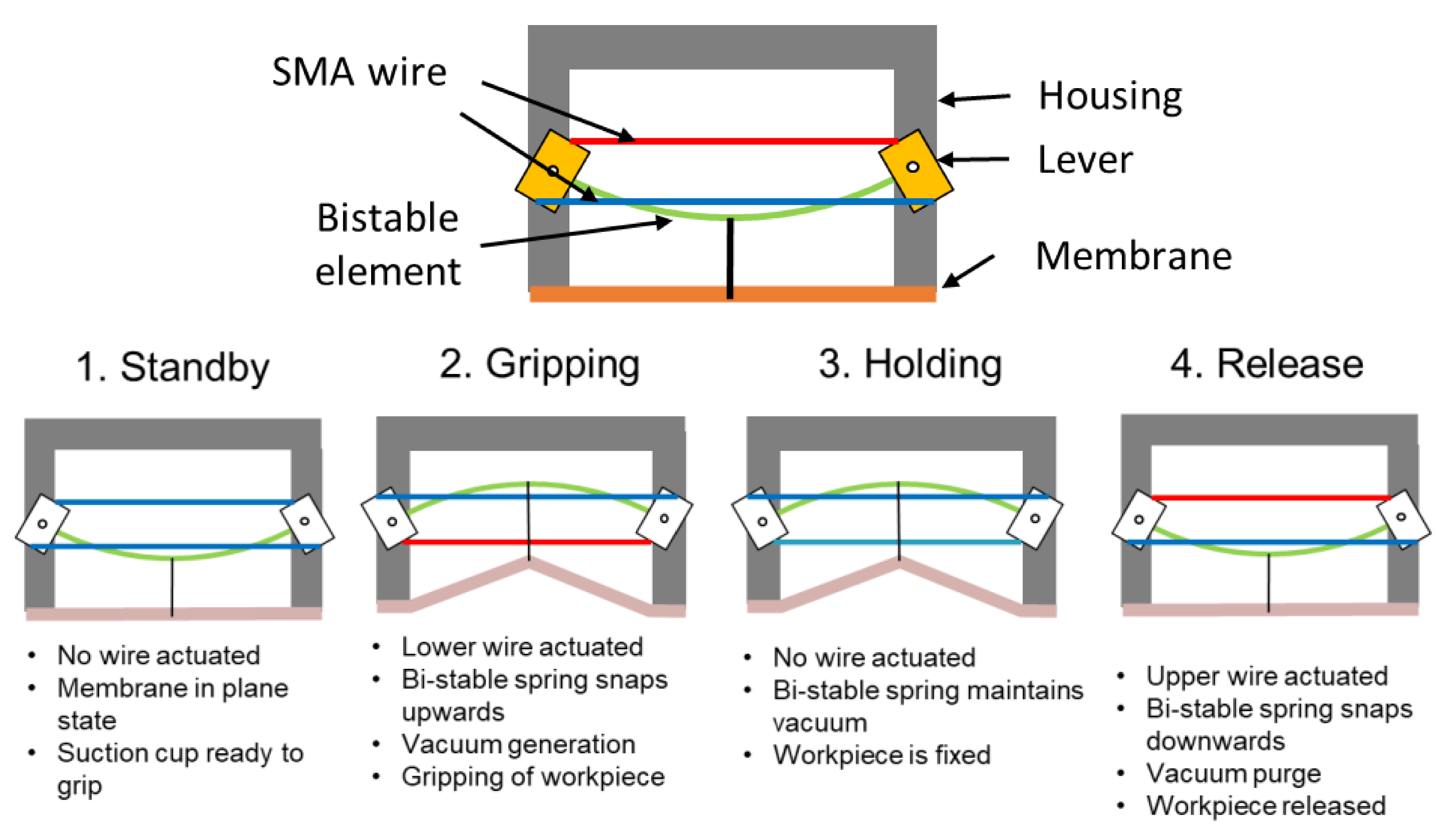
As an exemplary implementation of this actuator, the realization of an industrial vacuum gripper is presented. A schematic view of the concept of the bi-stable SMA vacuum suction cup is shown in
Figure 4 [
20]. The actuator mechanism again consists of a flexible deformable membrane, which is connected to a bi-stable spring. To actively switch between the two states, two antagonistic SMA wires are used. The orthogonal orientation of the levers related to the spring allows the parallel arrangement of the SMA wires to minimize the construction space. Activation of the bottom SMA wire allows the bi-stable mechanism to switch from the lower to the upper position. After the position toggle of the bi-stable element, the energy is switched off and the SMA wire cools down. When the membrane is sealed by the gripped object and deflected by the bi-stable element, a vacuum is generated inside the cavity between the membrane and the work piece. Release of the payload requires the activation of the top SMA wire. The energy-free holding of the two positions leads to an energy-efficient, cycle-time-reduced and fail-safe actuation mechanism.
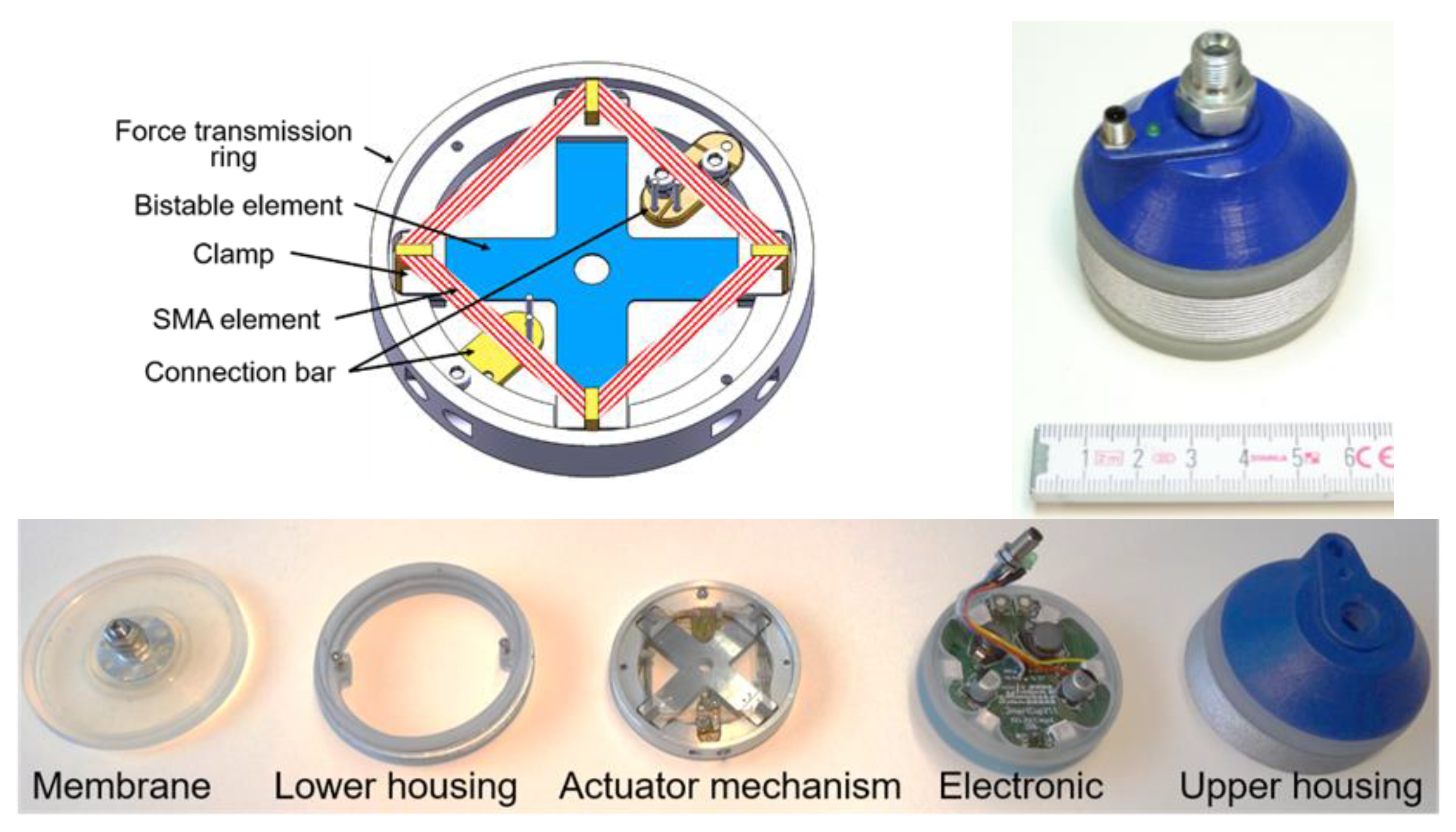
The design space is minimized by fitting the geometry of the actuation mechanism to the rotational geometry of the membrane. The upper side of the mechanical framework of the actuation mechanism is presented in
Figure 5. The membrane is directly connected to the bi-stable spring element. Maximizing the deformation force by a given area and minimizing the manufacturing effort, the leaf spring is designed in a crosswise configuration with four clamping points. The ends of the leaf spring are attached to a clamping mechanism which is pivot-mounted to enable the state toggle (up and down). The clamping mechanism is symmetrically mounted in the ring with a rotational joint. Additionally, the clamp provides the mounting point for the lever of the upper and lower SMA wire. The lever is needed for the transformation of the linear SMA force in a rotary movement to toggle the state of the bi-stable element. For reducing the cooling time and using the design space efficiently, the SMA element consists of bundles of thinner SAM wires (200 µm diameter) to optimize the surface to volume ratio for faster convective cooling. The ends of the SMA elements are attached to the connection bar, which at the same time represents the port to the electronics. The actuator mechanism and the membrane as well as the electronics are integrated in a closed housing to meet the requirements for harsh industrial environments, as shown in
Figure 5. The presented new prototype of an innovative SMA actuated bi-stable vacuum gripper enables an energy-efficient, fail-safe, noiseless gripping system without the need for compressed air.
3. High-Voltage SMA Activation
Commonly, in applications, an electric current is used to heat the SMA wire through Joule heating. Usually, to control the SMA contraction, a current between zero and five Amperes (depending on the wire diameter) is recommended by the wire manufacturers [
11,
12]. Therefore, the supply voltage must be adjusted according to the SMA wire’s electrical resistance. Controlling SMA wires with these recommended values, however, results in a slow actuation response due to the long time required to heat up the material and a great deal of heat is lost to the environment, which results in low efficiency. As an alternative approach, short high-voltage pulses can be used to achieve fast heating of the SMA wire [
16]. By means of this principle, it has been shown that it is possible to activate SMA wires much faster and in a more energy-efficient way. Even typical mains voltages, which supply alternating currents (AC) instead of direct current (DC), can be used for the activation of SMA wires under this control concept. The contraction can be controlled by varying the electric energy supplied by each pulse. For this purpose, the energy given to the wire is calculated in real time [
17].
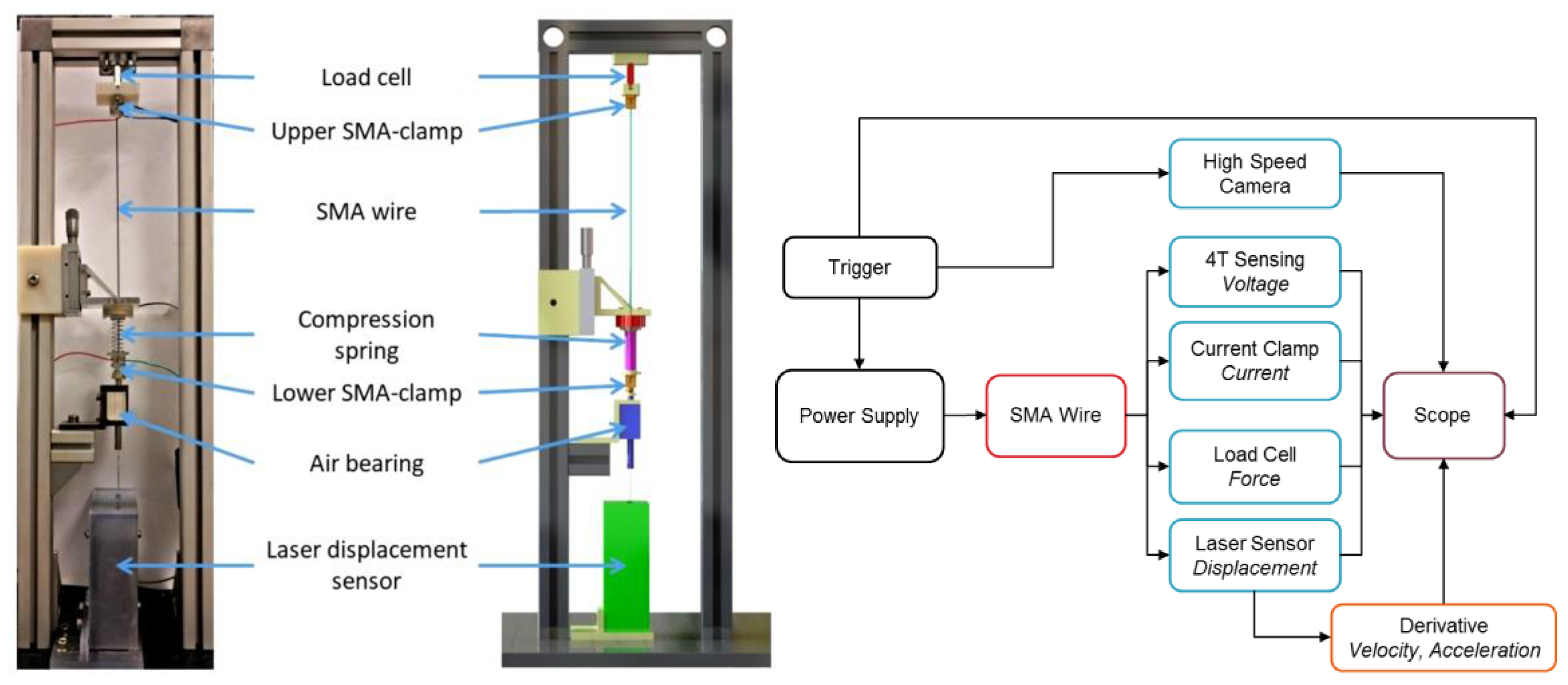
The experimental setup is shown in
Figure 6. A power supply is used to heat the SMA wire with an electric pulse. A laser displacement sensor measures the SMA wire stroke. The time derivatives of the displacement signal, i.e., velocity and acceleration, are calculated and plotted in post-processing. SMA force is recorded by a load cell of the type Futek LSB200. The voltage on the SMA wire is measured via four-wire sensing, while electrical current measurement is realized via a current clamp. Additionally, the whole experiment is recorded with an optical high-speed camera system, Olympus i-SPEED TR, for a better interpretation of the measurement results. Signal processing and data acquisition during the experiment are realized via an NI CompactRIO system. A compression spring can be placed between the bottom clamp and a micro-adjustment stage, allowing us to vary the SMA wire pre-tension. The air bearing guides the vertical motion with minimal friction. The laser displacement sensor detects the motion of the air bearing shaft. The SMA wire length in its austenitic state in this setup is 225 mm.
In an exemplary experiment with DC supply, a 76 µm SMA wire is activated in the conventional way using the suggested current of 150 mA in the datasheet [
12]. The SMA wire is activated with an activation pulse width of 1 s. The displacement reaches the value of 8.33 mm, which corresponds to a 3.7% stroke. The same wire is then activated at increasing voltages. At each set voltage, the activation pulse time (pulse width) is slowly increased until a displacement of 8.33 mm is reached. In all experiments, the initial force in the SMA wire is 0.28 N and a spring rate of 0.056 N/mm is used. The results of these experiments are shown in
Table 1. The activation delay describes the time interval from the start of activation until the bottom clamp of the SMA wire reaches the maximum displacement of 8.33 mm. The results show energy savings of almost 80% in comparison to the suggested quasi-static activation.
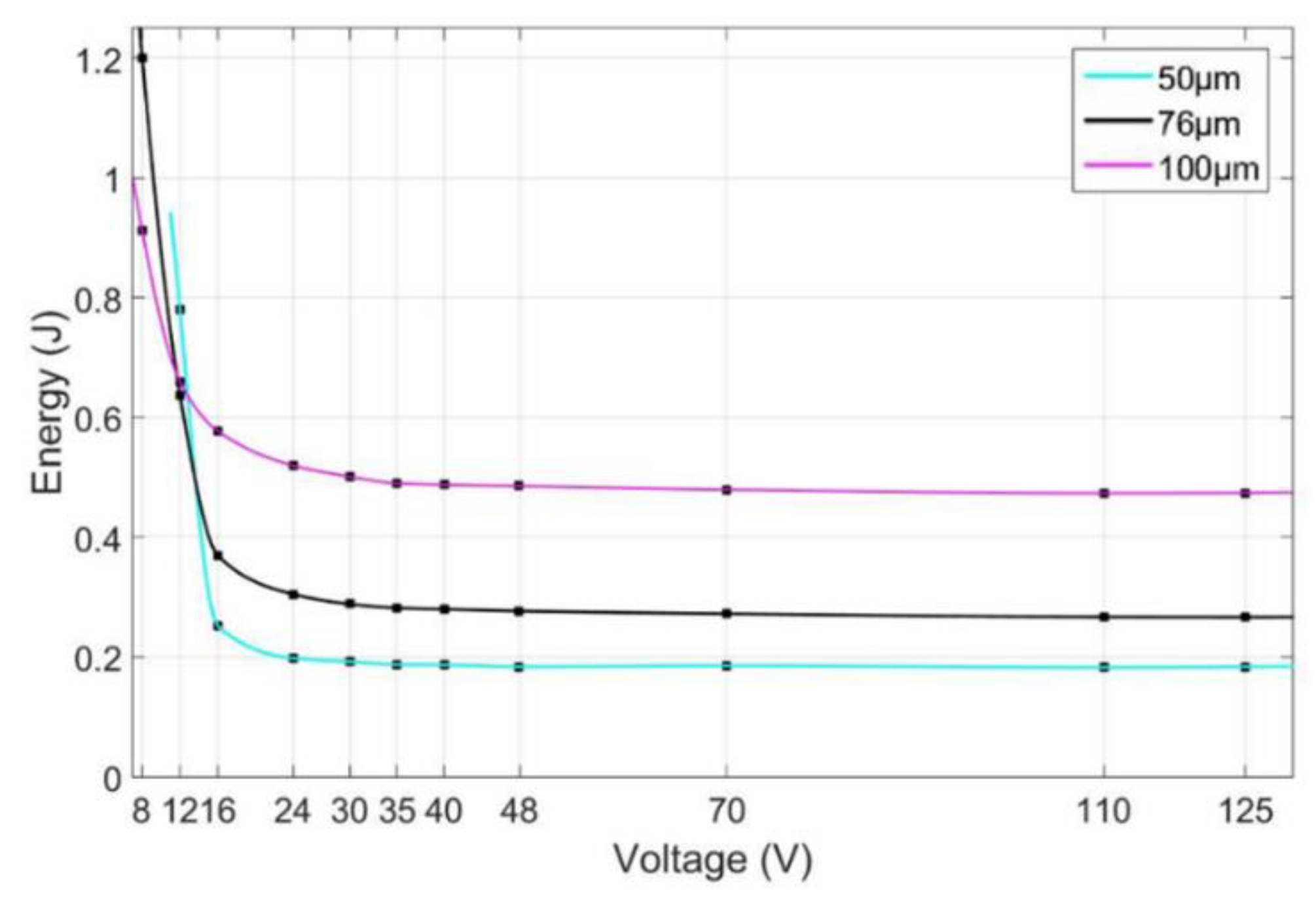
The same measurement sequence is performed for the SMA wire diameters of 50 and 100 µm. The total energy consumption at the different supply voltages is illustrated in
Figure 7. At low voltages, the thin wires need more energy to reach the same stroke. Thin wires have a higher surface-to-volume ratio and thus lose more energy to the environment during non-adiabatic activation. Between 12 and 16 V, the SMA wires start to reach the adiabatic region and the energy consumption settles at near-constant values. At these voltages, the thin wires require the lowest amount of energy. In small-diameter SMA wires, there is less material to be heated up before the actual phase transformation can begin.
In the case of AC supply voltages, relatively high voltage levels are present. The mains voltage extends from 100 up to 240 V
eff. Board voltage in ships can even be over 400 V
eff. The high peak voltages in these AC supplies require the resulting current to be split into pulses of short duration to prevent damage to the SMA wires. Therefore, a circuit board is developed to realize the pulse control of SMA actuators with AC voltage supplies. The concept of this control procedure is shown schematically in
Figure 8. To simplify the circuit board and the necessary electronic components, the AC voltage first is rectified. After this, a MOSFET (metal oxide semiconductor field-effect transistor) is used to switch the current through the wire on and off at any desired time.
Fluctuations in mains AC voltage supplies are common and, often, fluctuations of up to 10% are allowed. These deviations can have a negative impact on time-based pulses (such as pulse width modulation (PWM) control). Due to the high voltage levels in AC supplies, even low percentage deviations can affect the SMA wire’s energy consumption in a non-negligible manner. To compensate for such fluctuations and other noise in the voltage supply, a real-time energy measurement has been implemented. To calculate the converted energy in the SMA actuator, the voltage drops and the current through the wire are measured with a sample interval of 5 μs. With these measured values, every sample interval’s energy is calculated and summed:
This real-time energy measurement allows us to predefine an energy threshold for every pulse rather than a time duration. Thereby, every single pulse length is no longer predetermined. It depends on the actual voltage and thus on the actual current through the SMA wire.
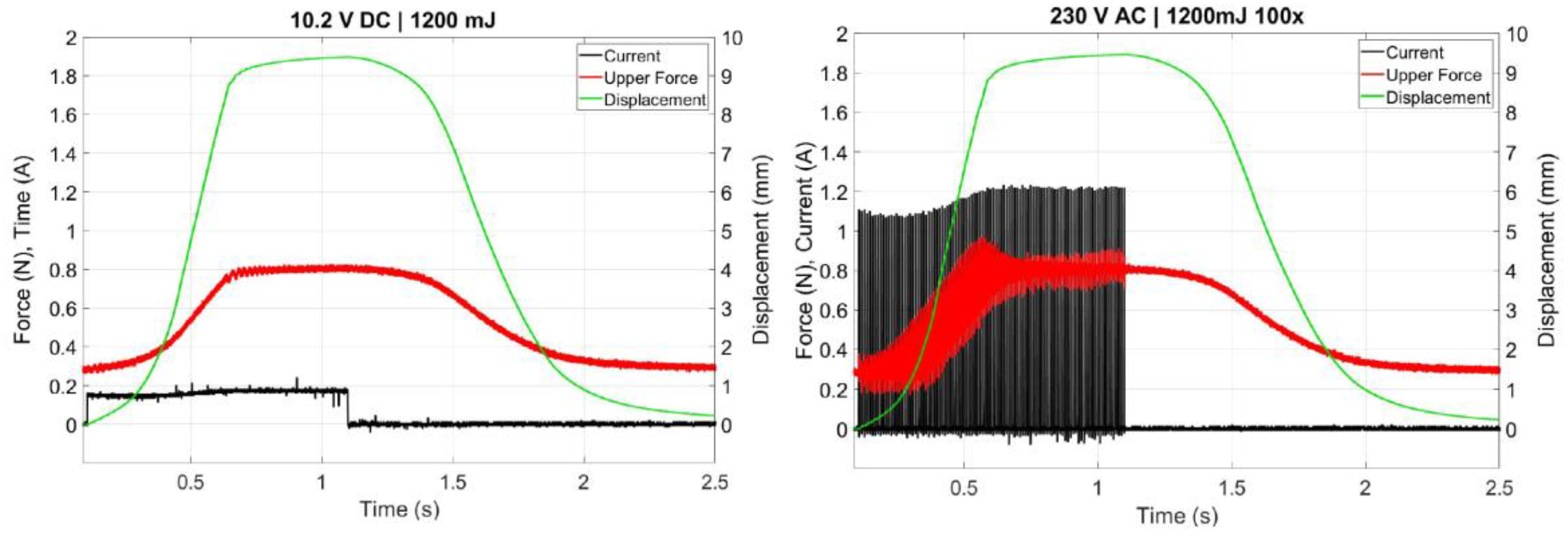
The reference experiment for the AC measurements results from a conventional DC activation, where again the SMA actuator is activated with a DC voltage based on the prescribed current in the data sheet of the manufacturer (
Figure 8, left-hand side). This results in a maximum displacement of 9.4 mm. The number of pulses used in this systematic set of experiments varies from 10 to 100. For every number of pulses, the energy threshold is gradually increased until the reference displacement is reached. A plot of the measurement with 100 pulses is shown in
Figure 8 (right-hand side). The necessary overall energy equals that used in the conventional DC activation (1200 mJ). Moreover, the flat displacement trajectory is similar to the conventional one.
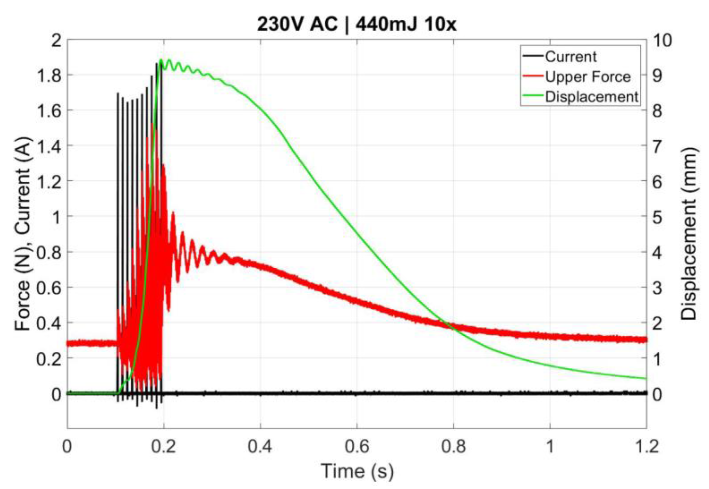
If the number of active pulses is reduced to 10, the overall energy needed to reach the reference displacement is reduced to 440 mJ; however, the energy for every single pulse (44 mJ) is much higher (
Figure 9). The reduced energy input can be explained by the faster activation and thus the lower energy loss to the environment during the heating of the SMA wire. With 10 pulses, only 36.6% of energy is needed to reach the reference displacement.
4. Conclusions and Perspective
This paper has given an overview of different methods to increase the low energy efficiency of SMA actuator systems, which is a well-known disadvantage of this technology. For a wide range of possible applications, a bi-stable design concept can lead to energy-free actuator positions. This mechanism has been illustrated through the example of an industrial vacuum gripper system. In addition to the mechanical design, efficiency can be increased by the demonstrated control concept of high-voltage activation pulses. Experimental studies for DC and AC power supplies have shown possible energy savings of 60–80% compared to conventional SMA control.
Future work will address the transfer of these concepts into different application-based prototypes and their validation. In particular, the realization of compact power electronics for the control concept, which can be integrated in commercial systems, is one of the upcoming challenges.


