Proceeding Paper

Analysis of Field Oriented Control of Permanent Magnet Synchronous Motor for a Valveless Pump-Controlled Actuator †

IHA-Innovative Hydraulics and Automation, Faculty of Engineering and Natural Sciences (ENS), Tampere University, Korkeakoulunkatu 6, 33720 Tampere, Finland
*
Author to whom correspondence should be addressed.
Presented at the First International Electronic Conference on Actuator Technology: Materials, Devices and Applications, 23–27 November 2020; Available online: https://iecat2020.sciforum.net/.
Proceedings 2020, 64(1), 19; https://doi.org/10.3390/IeCAT2020-08491
Published: 20 November 2020

Abstract

:
Earlier research demonstrated that a pump-controlled hydraulic system combines the best properties of traditional hydraulics and electric intelligence. Thus, the new system has been proposed as a replacement for conventional valve-controlled systems, to improve the energy efficiency in non-road mobile machinery in particular. One of the pump-controlled systems can be realized via direct control of hydraulic pump/motor by varying speed of prime mover. Electric motor (EM) as a prime mover attract with higher efficiency (more than 90%) and a wide range of speed regulation. These advantages allow to improve the system efficiency and decrease the energy consumption in electric and hybrid non-road mobile machinery. Further EM’s efficiency improvement can be achieved by using vector control systems, which provide rotor magnetic flux control proportionally to the shaft’s speed. Considering all vector control’s benefits (high accuracy of speed control, smooth start and smooth rotation of the motor in the entire frequency range, quick response to load changes, increased control range and accuracy of regulation), the electro-hydraulic systems and influence of electric part on hydraulic one is not investigated widely. Therefore, in this paper Field Oriented Control (FOC) is analyzed as One of the most perspective vector control systems for electro-hydraulic actuator application with a Permanent Magnet Synchronous Machine (PMSM) as a prime mover. In this study, Direct-driven hydraulics (DDH) was considered as a study case. A detailed model of the PMSM control system with DDH was built in MATLAB/Simulink. The behavior of the DDH system was investigated by transient processes analysis of EM, pump, and cylinder in the normal and failure modes. The system demonstrates a difference between reference and simulated speed about 0.33% and 11.75% of average torque fluctuations. The behavior of the system in failure mode demonstrated multiple excesses of rated parameters.

1. Introduction

Commonly, valve-controlled systems are used in various areas (stationary and mobile machinery applications) [1]. Valve-controlled systems utilize a constant speed of prime mover and control a flow of hydraulic system by the directional valves. Such types of conventional hydraulic systems are characterized by low efficiency, due to throttle losses (which also produce heat), and high energy consumption caused by continuous work of a prime mover [2]. However, pump-controlled systems allow mitigate negative features of valve-controlled ones and get the advantage of basic features of hydraulics. As one type of a pump-controlled system, direct-driven hydraulics (DDH) was proposed in [3]. DDH consists of two hydraulic pumps/motors with different displacements and a hydraulic accumulator to match unbalanced flow in a single-rod cylinder and oil tank. According to [4], a combination of a pump-controlled system with an electric prime mover increases performance and efficiency. EMs are utilized as prime movers for several decades already. The appearance of intelligent adjustable control systems for EMs accelerated the development of new controls in all areas, which uses rotational power. EMs can work discontinuously and it is more adjustable due to many types of control [5]. According to [6], the Induction motor is the most used machine in electro-hydraulic systems, due to its price and simplicity. However, Permanent Magnet Synchronous Machine (PMSM) is has a better size/power ratio due to compact design-integrated winding and permanent magnets [7]. Therefore, for this research, PMSM was chosen as a prime mover for the maximization of performance and optimization of energy resources. As a result, a combination of the pump-controlled structure with PMSM can improve performance of the system (because of high performance of EM), leakage losses (because of decreasing the number of pipes and hoses), increase the flexibility of a system, and decrease the amount of noise and emissions, payback time in a long-term perspective (a price of electricity significantly less than a price of diesel fuel) [8]. One of the main control methods of PMSM which is called field oriented control (FOC) is used in this research, because of the smaller transient process time in comparison with other vector control systems. This control method is vector-based, because of the geometrical expression of main control variables, which are represented as vectors into a mathematical space. FOC was invented by Siemens’ F. Blaschke in Germany and was not changed over time (except cases of modernization by neural networks and fuzzy logic) [9]. The main purpose of the research is the investigation of the behavior of PMSM controlled by a three-level frequency converter with a DDH system as a load. The behavior will be investigated under normal and failure mode.
Section 2 describes the structure of the electro-hydraulic drive with a control system and modeled components. The whole system is simulated and analyzed in Section 3 and the results are discussed in Section 4. Conclusions are drawn in Section 5.

2. System Description

In this chapter structure of the DDH system is described. Section 2.1 describes the pump-controlled actuator schematic and its components. Section 2.2 consists of the electric drive description, power electronics system, and parameters of a PMSM. Section 2.3 describes the whole system structure, which combines FOC and hydraulic position control.

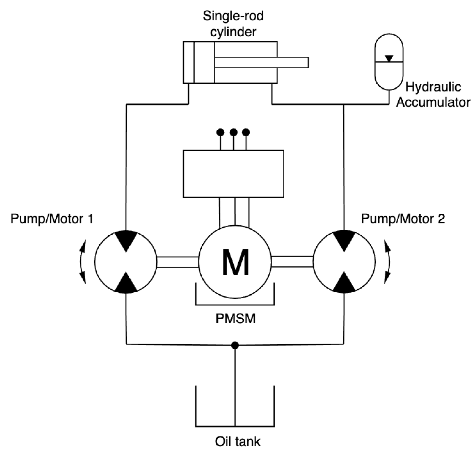
2.1. Pump-Controlled Actuator
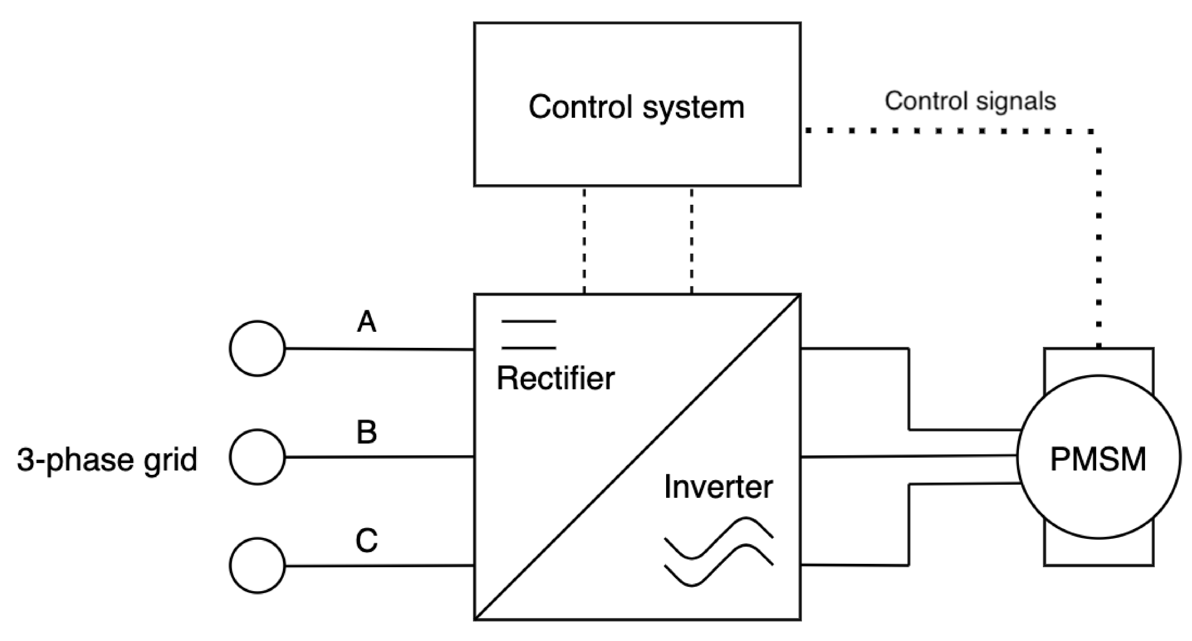
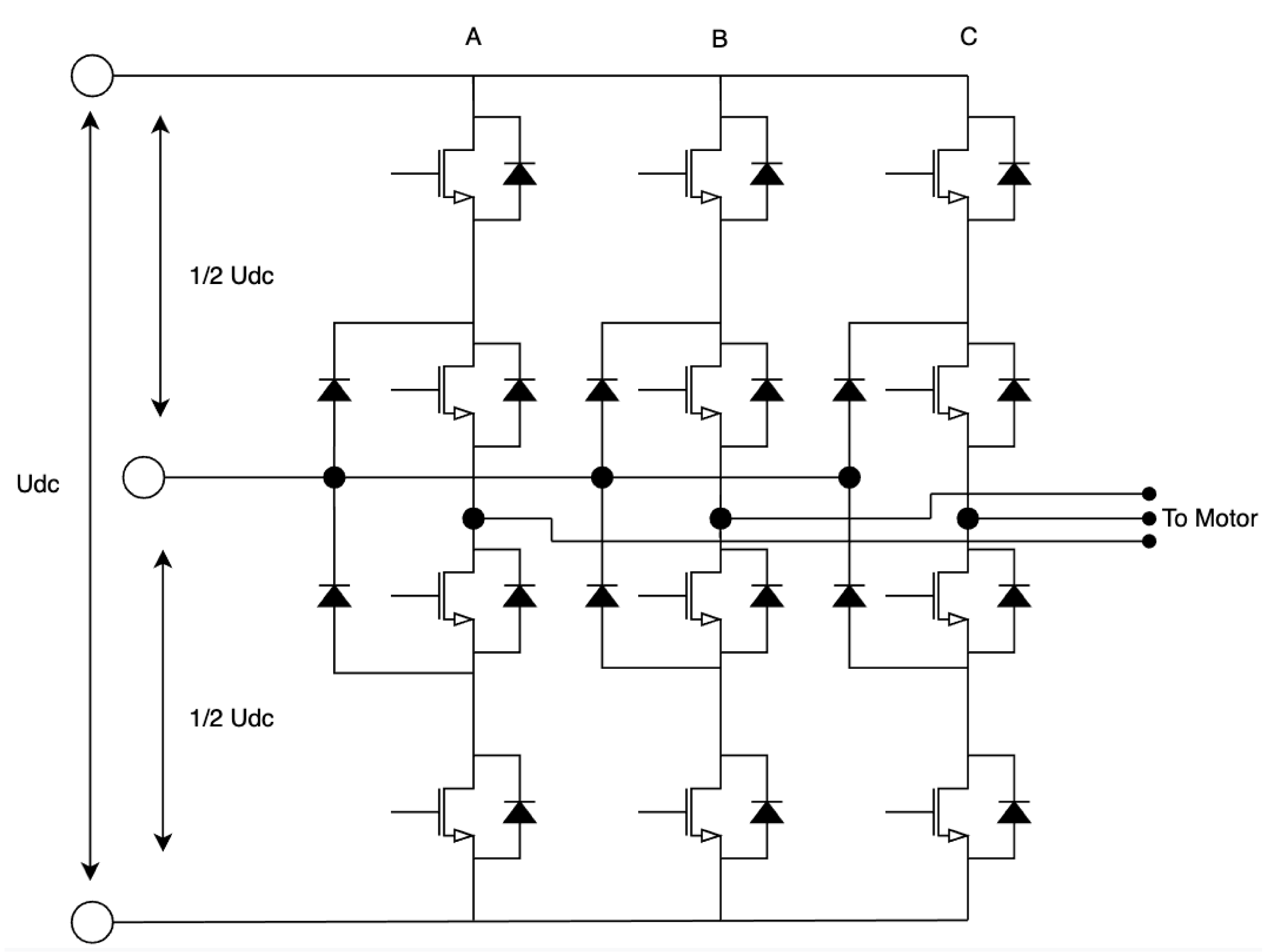
The hydraulic drive consists of two fixed-displacement hydraulic pumps/motors, with different displacements, a single-rod double-acting hydraulic cylinder, hydraulic accumulator, and oil tank. DDH drive is represented in Figure 1 below.
Flow changing is implemented by variable rotational speed of prime mover.
Q = D n ,
where
D = c o n s t , n = v a r i a b l e .
The investigated schematic of DDH is simplified for this research. Safety valves (pressure relief valves) are omitted from this stage of research. For experimental investigations, pressure relief valves are needed. The utilization of a single-rod hydraulic cylinder brings challenges such as unbalance input and output flow due to different areas of cylinder sides [3]. A hydraulic accumulator is used to balance this flow. A detailed description of the components utilized in the electro-hydraulic system is represented in Table 1.

2.2. Electric Drive

In this research, a utilized model of the electric drive consists of three-phase PMSM, rectifier, inverter (rectifier and inverter can be called as frequency converter), and control system. Three-phase AC is rectified and used in the inverter for controlling of frequency and amplitude of a new three-phase AC, which feeds PMSM. This is the main control principle of adjustable drives. In PMSM voltage and current sensors are utilized to calculate all needed variables. Electric drive with PMSM is fed by 220/380V AC grid. The structure of the electric drive is represented in Figure 2 below.
Emerson Control Techniques Unimotor FM115 U2C300 VACAA115190 was chosen as a prime mover. All motor parameters are represented in a Table 2, further.
A three-level voltage inverter is used in the frequency converter. This inverter demonstrates higher accuracy and lowers Total Harmonic Distortion (THD), which decreases negative disturbances in the whole system (torque ripples, noise, etc.) [10]. The schematic of the three-level inverter is illustrated in Figure 3.
Such an inverter has twelve Insulated-Gate Bipolar Transistor (IGBT) transistors and uses one of the twenty-seven switch combinations at any time. Every combination corresponds to one of the twenty-seven vectors, which affects the creation of a voltage vector. Chosen Space Vector Pulse Width Modulation technology (PWM) increases the efficiency of the inverter, and frequency converter at all, but it requires more computational power because all combinations of iGBT transistors are considered as vectors in the three-phase coordinate system. Too high frequencies can even make output voltages and currents worse and the frequency 1200 Hz was set as an operating one. This approach needs to use calculations of projections, which determines the working period of iGBT. Such calculations need additional computational power.

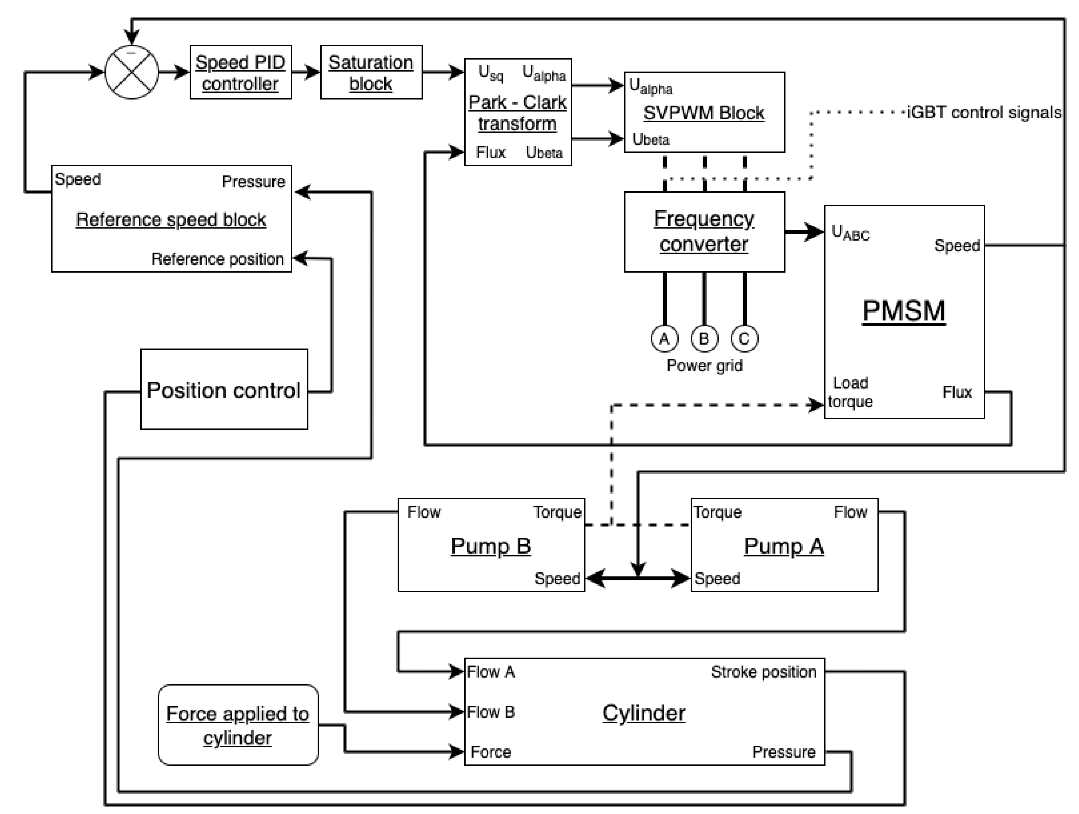
2.3. Control System Description

This subsection describes the complete system, description of the system, and control approach. The whole system consists of a variable-speed electric motor and a pump-controlled hydraulic actuator. Variable speed electric motor is regulated by FOC. The hydraulic drive uses a position control. The structure of the control system is represented in Figure 4 below.
FOC is a rotor-oriented vector control method, which uses the geometrical transformation of three-phase current and voltages to rotational and stationary two-phase form. PMSM block simulates processes of the electric motor with two main parameters at the input: three-phase voltage and load, and two parameters at two main parameters at the output: speed and flux. Speed and flux are used as system feedback. Frequency converter changes AC from the grid to AC with other frequency and amplitude, that allows changing the rotational speed of EM. The frequency converter block takes voltage in a three-phase coordinate system, which is got from the stationary coordinate system (Clark coordinates) by geometrical projections. Voltage in Clark coordinates representation can be done due to Park-Clark transform. Park coordinate system is rotational and an angular speed of this coordinate system is equal to the rotational speed of a rotor, consequently, projections of voltage vector change continuously while the machine works. Saturation block limits the output of a speed controller for better stability and decreasing the probability of increasing oscillations. The speed controller has a PI-controller structure. An output of the speed controller is a torque. The control system has double feedback using flux and speed. Current flux is needed for shaft position determination, reference flux is equal to zero, for the comfortable orientation of the coordinate system at 90 degrees.
DDH drive position control is implemented by using a position of the cylinder’s stroke and pressure inside chambers. The position of the stroke is used as feedback. When a piston is in end positions, the control system creates a signal to position the reference block, which stops the rotation of the prime mover. The speed of the prime mover can be changed, using the pressure data, in the cases of rapid increase.

3. Modelling

Section 3.1 represents systems response on step-function. Section 3.2 and Section 3.3 consist of a simulation of normal operation and failure mode of the system correspondingly under the constant load. Modeling with utilization Matlab/Simulink is the main facility of the research. Standard blocks and Simscape library were used for a hydraulic model building. Simulation time did not exceed 13 s. Models were built with the use of differential equations of PMSM and steady-state condition equations. The equilibrium state of FOC is described in rotor’s equations (for more details refer to [11]). The model of control systems was successfully built via theories of non-linear automation control and electric drives. The model was tuned with information obtained from previous experimental studies with DDH [12].

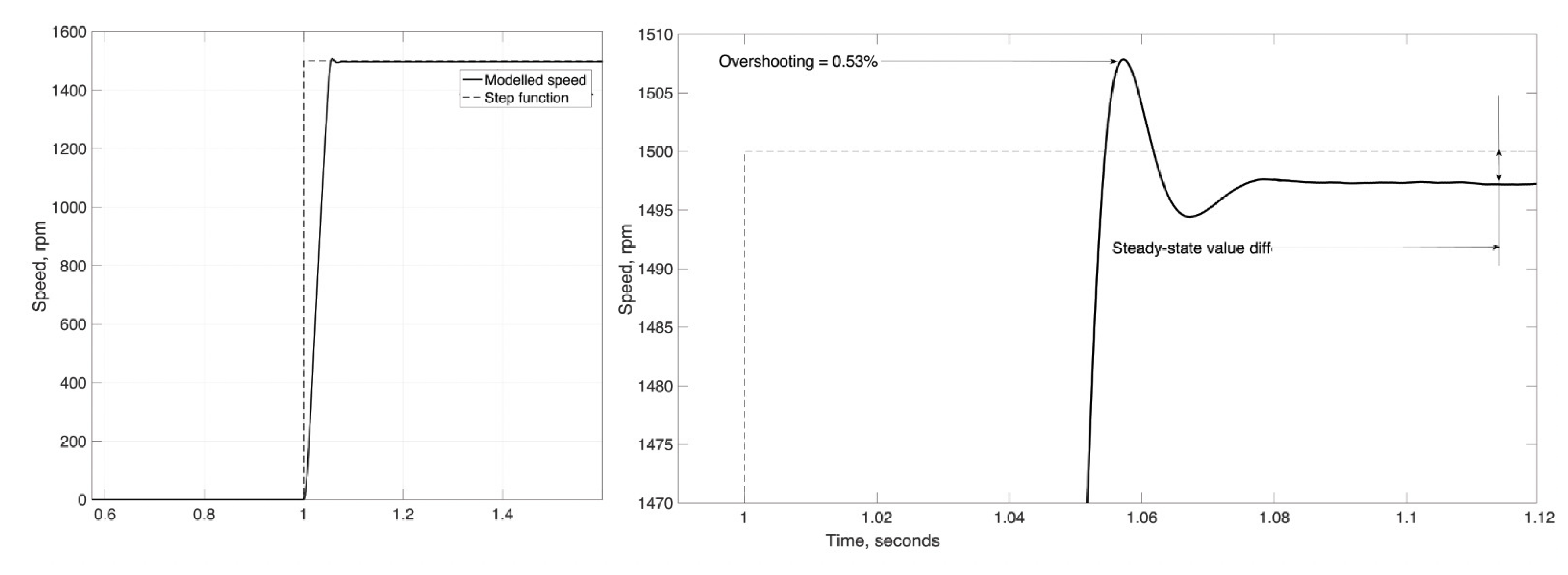
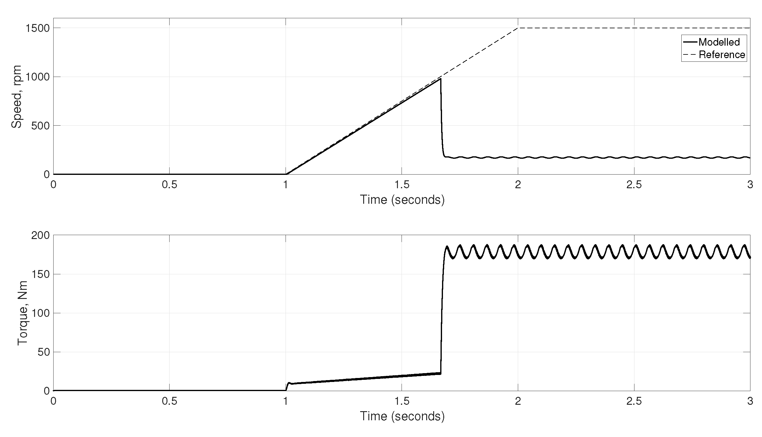
3.1. Step Function Response

The first part of the simulation uses a step function speed reference signal with an amplitude of 1500 rpm. In this subchapter hydraulic load increases also simultaneously at this moment, because pumps are connected to the shaft. The form of the signal and simulated speed of the system is represented in Figure 5.
DDH system has a very fast transient process, which can be explained by small mass, inertia, and load, which did not exceed rated values (power equal 2.54 kW). The rising time of speed (time which is needed for the first reaching of reference value) is about 0.051s. Overshooting is equal to 0.53% (it corresponds to the difference between reference and simulated values equal to 8 rpm). A character of the transient process is aperiodic with a steady-state value of 0.16% less than reference one. Utilization of bigger mass will increase a load torque, and as a result, will make the transient process monotonic.
Such a small transient process time is theoretically possible to reach, however, it creates challenges. Immediate accelerating of EM increases an electromagnetic load of the EM and current as a result. Tuning of the system is possible at a fast response mode, but the real system is never able to work at the same fast reaction rate, due to inertia and physical limits. Parameters of the system transient process are represented in Table 3.

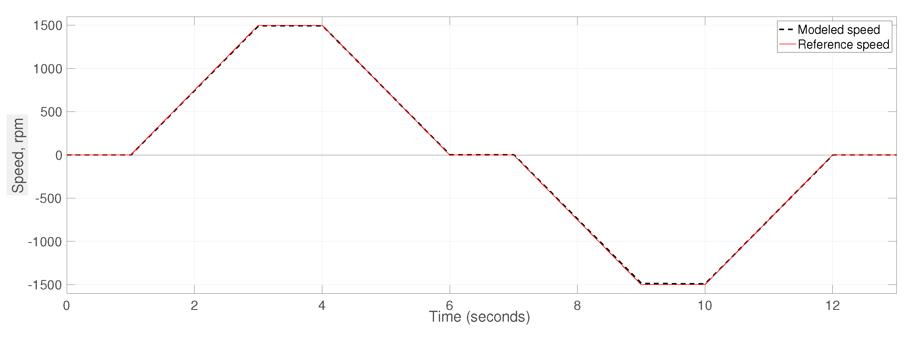
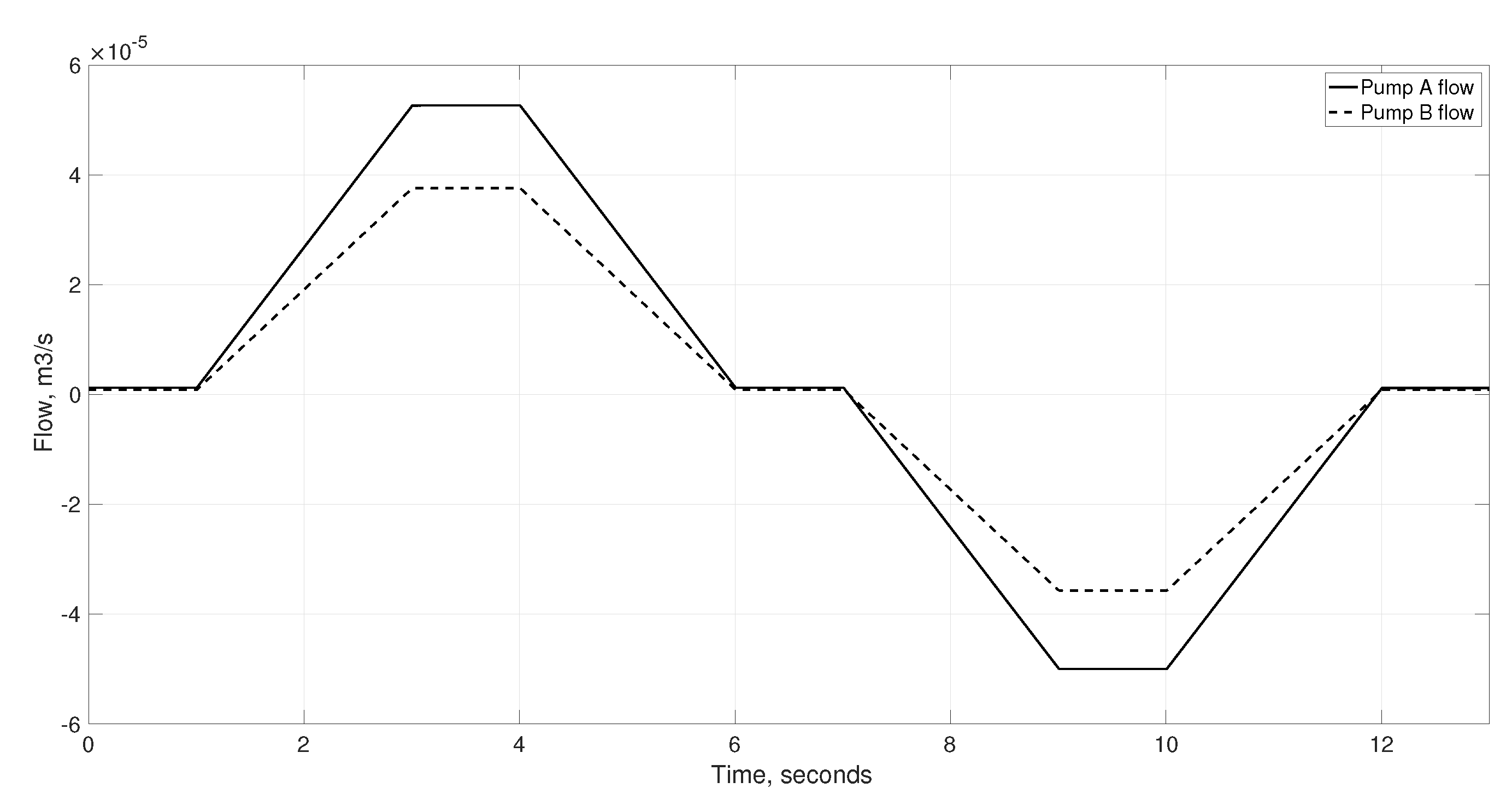
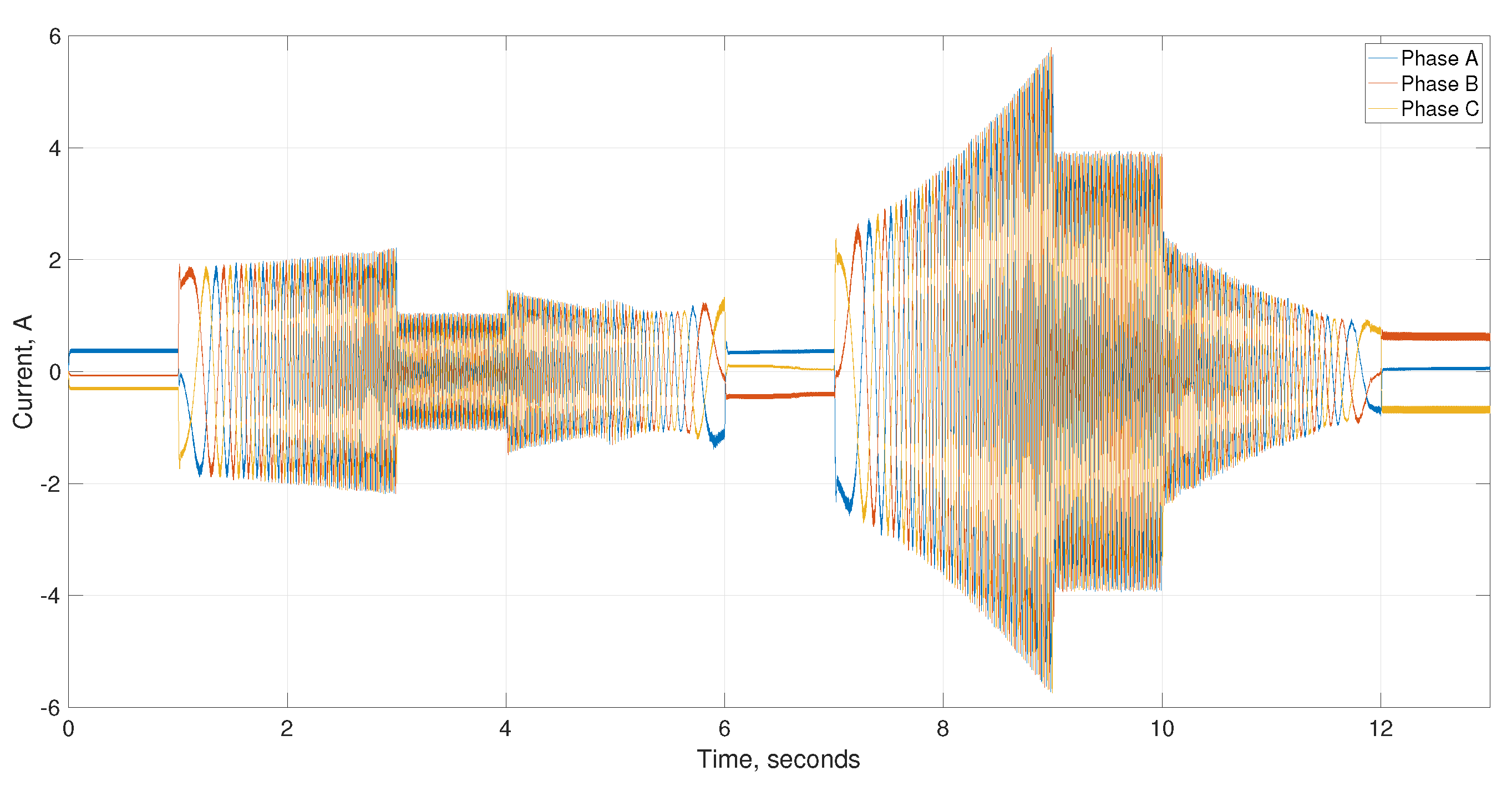
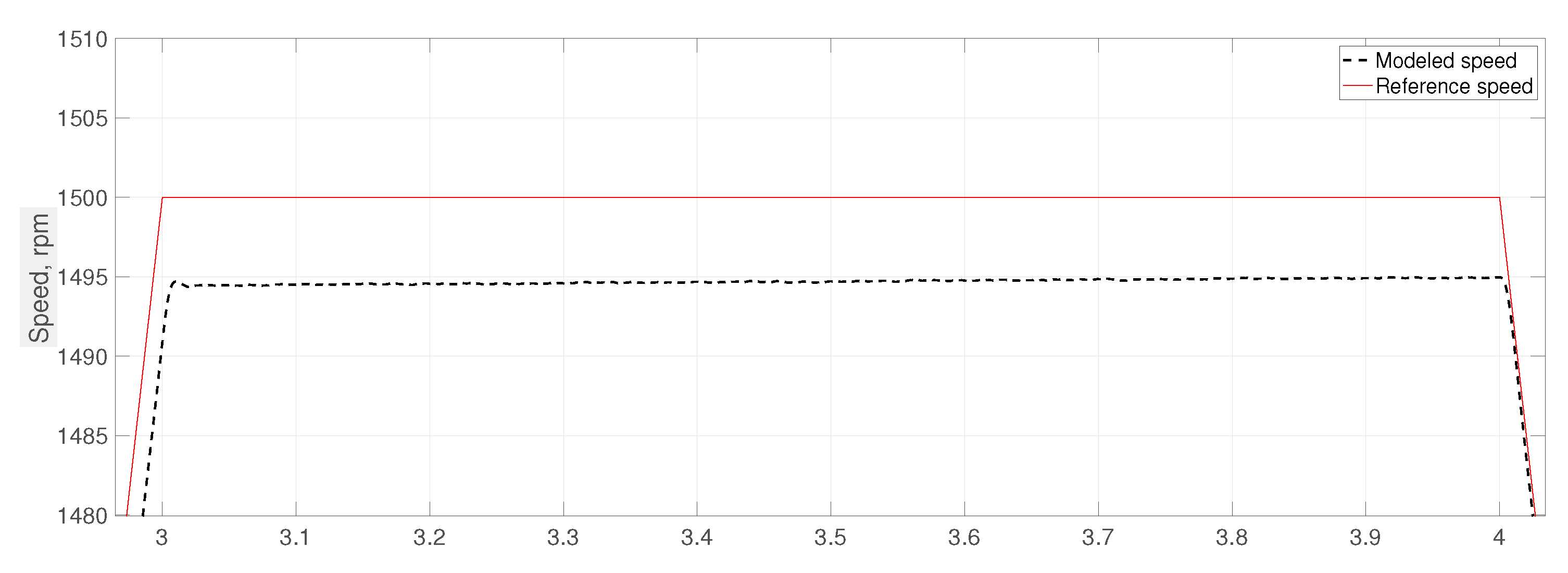
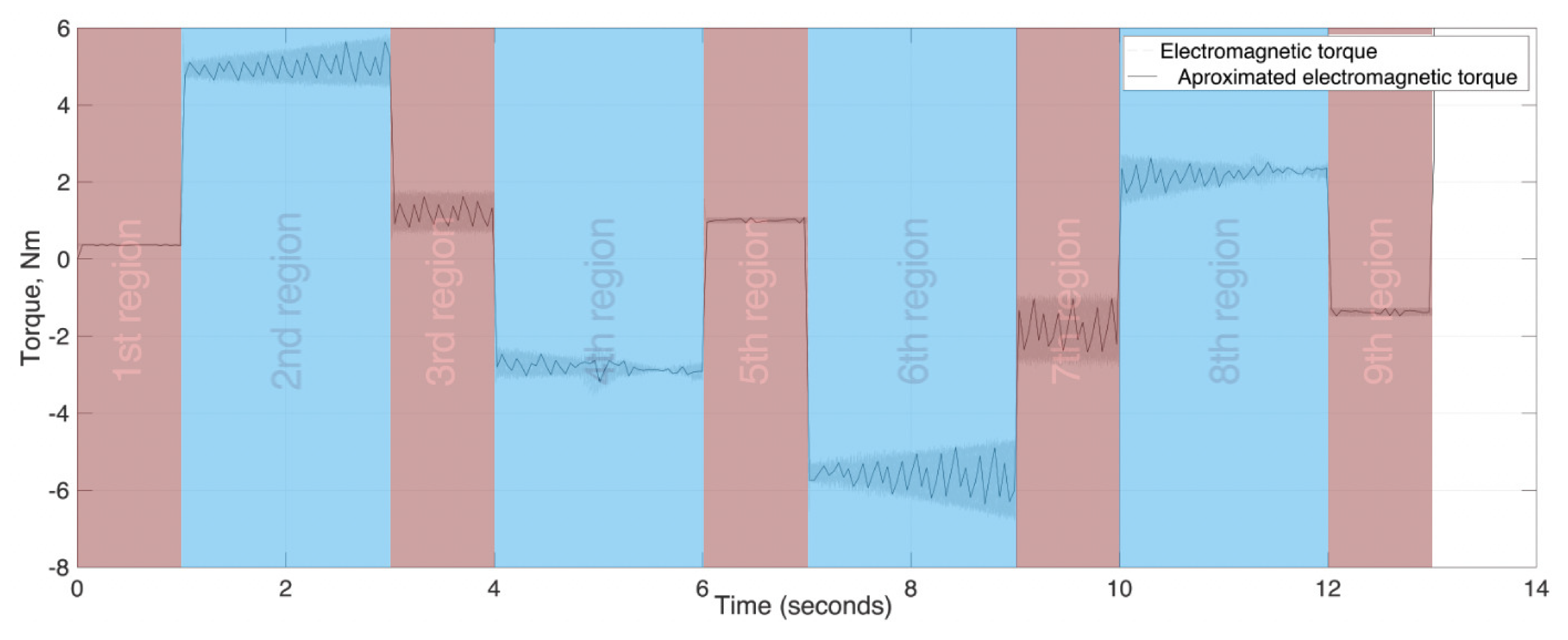
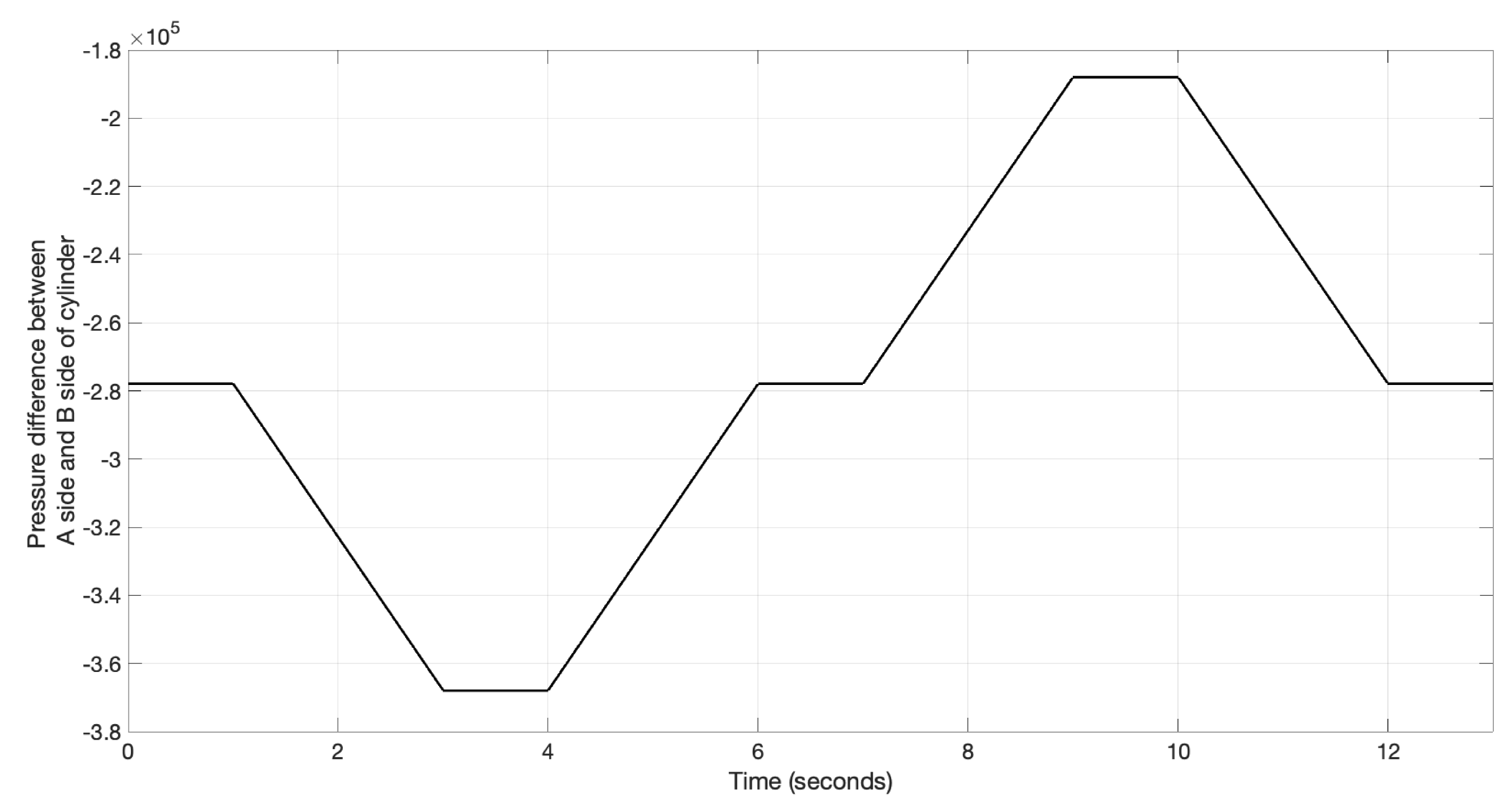
3.2. Operation in the Normal Conditions

The second part of the simulation utilizes a variable reference speed signal. A whole working cycle spend 13 s for extending and retracting the cylinder stroke. Acceleration of the EM is selected in such a way that, currents and electromagnetic torque are in the range of acceptable values (overshooting of the transient process must be less than 20 %, rising time must be no more than 10% of transient process time). EM’s speed reference is specially designed for a short movement of stroke without approaching of cylinder’s ends. Modeled and reference speeds of the whole system are represented in Figure 6 and Figure 7. Figure 7 indicating the detailed view of a holding state (steady-state mode) of the cycle of Figure 6.
According to Figure 7, the difference between reference and modeled speeds in the steady-state mode is about 5 rpm (0.33%). It means that working speed amplitude id +1495 rpm. This speed is less than the rated speed of pumps (rated pumps speed is 2000 rpm), but such mode allows us to decrease an EM’s load and electromagnetic torque as result. Decreasing the load as result will reduce the electromagnetic torque of the motor and power consumption. Electromagnetic torque behavior is represented in Figure 8.
According to Figure 9, torque amplitude is less than rated (is about 5.8 Nm). The working repeating sequence of torque can be explained by dividing the characteristics from Figure 9 into several regions.
  • In the 1st region (from 0 s to 1 s) torque is around zero because EM has no load and zero reference speed, but currents and voltages are applied to EM to maintain the required position.
  • 2nd region is from 1 s to 3 s. Increasing reference speed launches electromagnetic processes in the motor and rotation of the shaft gets an additional load from the hydraulic part. Maximal positive torque is achieved.
  • 3rd region is from 3 s to 4 s. At this moment acceleration is equal to zero and the motor has a constant speed, however, the hydraulic load is still applied.
  • 4th region is from 4 s to 6 s. This period has deceleration of the motor and the same hydraulic load. Torques from hydraulic and electric parts have different signs and the resulting electromagnetic torque is the smallest non-zero one.
  • The 5th and 9th regions are identical to the 1st.
  • 6th, 7th, and 8th correspond to 2nd, 3rd, and 4th regions but with a negative sign. As a result, the level of torque fluctuations is about 10% in the positive part (motoring mode) and 13.5% in the negative part (generating mode). The negative part demonstrates a higher level of fluctuations, because of applied to the cylinder mass, which creates an additional lowering force disturbing the system.
Figure 9 demonstrates the cylinder stroke position. The symmetric behavior of the graph with operation in the stroke length region proves that the created model works as expected. The form of the cylinder stroke position graph follows the speed of EM. Figure 10 demonstrates the output flow of pumps. Flow is in direct ratio with rotational speed (in the case of fixed displacement systems). Figure 11 represents the pressure behavior of the system.
Behavior of the consumed current is demonstrated on the Figure 12.
According to Figure 12, the maximal current amplitude is 5.8 A, that less than the rated current of the used PMSM. Utilization of a three-level inverter, allowed to get THD no more than 6.12% in steady-state mode.
According to modeling in the normal conditions, the system with a satisfying possibility of operating was got. The behavior of flow, the pressure of hydraulic parts, and the torque and speed of the hydraulic part demonstrate a normal behavior. Table 4 summarizes the main modeled results for normal conditions.

3.3. Operation in Failure Mode

The main goal of this subsection is the research of systems behavior under enormous conditions (overrunning the motor), such as working after full retracting/extending of the cylinder.
Figure 13 represents the position of the stroke, currents, flow of pumps A and B. Figure 14 demonstrates the speed and electromagnetic torque behavior of PMSM.
After 1.6 s of simulation, stroke reaches the end of the cylinder and pressure increases dramatically. With increasing pressure, load torque increases simultaneously. Electromagnetic torque is a result of the load and self-created torque of EM. Electromagnetic torque has a direct ratio with consuming current. Increasing the current 13 times in comparison with the rate can be noticed. Rotation of EM falls, because of high load. Load and currents higher than rated in such order will destruct equipment and can bring harmful consequences.
According to Figure 13 and Figure 14, simulation results are summarised in the Table 5.

4. Discussion

Despite utilized simplifications in the created model (no friction and no leakages), accurate positioning within the entire piston stroke demonstrated that the model works as expected. Simulation of the DDH system demonstrated that the fast transient process was reached. The rising time of 0.051 s with overshooting 0.53%, the whole transient process time is about 0.13 s and steady-state value difference in comparison with reference signal 0.16% with step reaction function allow to work at steady-state mode with minimal losses. However, step function reaction can not be used in the normal work of the system, because of very high torque and currents (there is a possibility of EM destruction). Normal mode simulation demonstrated, that simulated speed losses just 0.33% in comparison with referred speed (normal operation conditions). Fluctuations of the torque 10% in positive part (motoring mode)and 13.5% in negative part (generating mode) of electromagnetic torque behavior during normal operation condition. It can be explained by the vertical placement of the cylinder. Force, which is applied to the stroke of the cylinder, has the same direction as stroke movement. Failure mode (overrunning motor) demonstrated multiple exceeding the maximum rated as such values as current, electromagnetic torque, pressure, and flow. Increasing the values from acceptable numbers to extremely high needs less than 0.01 s (it means that, system destruction is possible even with relief valve, due to inertia). Increasing pressure, electromagnetic torque, and current dropdown rotational speed of PMSM and flow as result. Current exceeds the rated value in 12.8 times (75.52 A). Electromagnetic torque exceeds peak value in 4.79 times (180.1 Nm) in the positive rotation direction and steady-state mode. The simplicity of the created model (no friction and leakages) made the tuning of the system easier. However, utilization of Matlab/SimScape blocks for a hydraulic part, need to be upgraded in future research by a more accurate hydraulic model and validated by experimental study. Electromagnetic torque fluctuations can be minimized further. More precise tuning of the FOC, utilization of variable structure control, and using fuzzy logic or artificial neural networks can be utilized for this task. An optimized and accurate tuned control system can decrease electromagnetic torque, consumed current, and overall power consumption. The overall use of hydraulics as a load (compare to previous work [13]) for EM drive reduces stability and increases fluctuations. It means that EM’s control needs to be optimized and tuned before the connection with the electro-hydraulic actuator (it was demonstrated also earlier in [14] by experiments). The ability to regenerate during the lowering phase of the cycle (generating mode) needs to be added to the system model in the future. It will improve the behavior of the system at lowering the payload.

5. Conclusions

In this research, a simplified DDH system was investigated with detailed PMSM controlled by FOC in Matlab/Simulink. Step function response, normal and failure (overrunning) mode simulations were used for evaluation of behavior EM and hydraulic system An acceptable level of stability and accuracy was reached. Step function response demonstrated a small rising time (0.051 s) and transient process time (0.13 s). Overshooting of the system did not exceed 0.53% and the difference between reference and simulated speeds in steady-state mode is 0.16%. Simulation part with hydraulic load represented higher speed difference between reference and simulated speed in steady-state mode 0.33% and 11.75% of torque fluctuations. Fluctuations have a decaying character. The maximal current amplitude was 5.8 A. This indicated load reached a maximum for the DDH system. Failure mode (overrunning motor) demonstrated multiple exceeding the maximum rated as such values as current, electromagnetic torque, pressure, and flow. Current exceeds the rated value in 12.8 times (75.52 A). Electromagnetic torque exceeds peak value in 4.79 times (180.1 Nm) in the positive rotation direction and steady-state mode. This research demonstrated key features of the behavior of electric drive within DDH and pointed out the next development steps. Results which were obtained were satisfactory and will be improved in further research.

Author Contributions

conceptualization, V.Z. and T.M.; methodology, V.Z. and T.M.; software, V.Z.; writing—original draft preparation, V.Z.; writing—review and editing, T.M.; supervision, T.M., project administration, T.M.; funding acquisition, T.M. All authors have read and agreed to the published version of the manuscript.

Funding

This work was enabled by the financial support of Academy of Finland (project ESTV) and internal funding from the Department of Automation Technology and Mechanical Engineering, IHA group at Tampere University, Finland.

Abbreviations

The following abbreviations are used in this manuscript:
EMElectric Motor
PMSMPermanent Magnet Synchronous Machine
FOCField Oriented Control
PWMPulse Width Modulation
DDHDirect-Driven Hydraulics
ACAlternative Current
DCDirect Current
SRMSwitched-Reluctance Motor
THDTotal Harmonic Distortion
MCUMicrocontroller Unit

References

  1. Manring, N.D.; Fales, R.C. Hydraulic Control Systems; John Wiley & Sons: Hoboken, NJ, USA, 2019. [Google Scholar]
  2. Love, L.J. Estimating the Impact (Energy, Emissions and Economics) of the US Fluid Power Industry; ech. Rep. ORNL/TM-2011/14,1061537; Oak Ridge National Laboratory (ORNL): Oak Ridge, TN, USA, 2012. [Google Scholar]
  3. Minav, T.; Sainio, P.; Pietola, M. Direct-driven hydraulic drive without conventional oil tank. In Proceedings of the ASME/BATH 2014 Symposium on Fluid Power & Motion Control, Bath, UK, 10–12 September 2014. [Google Scholar]
  4. Minav, T.; Laurila, L.; Pyrhönen, J. Analysis of electro-hydraulic lifting system’s energy efficiency with direct electric drive pump control. Autom. Constr. 2013, 30, 144–150. [Google Scholar] [CrossRef]
  5. Guo, Q.; Zhang, C.M.; Li, L.; Zhang, J.; Wang, M. Maximum Efficiency Control of Permanent-Magnet Synchronous Machines for Electric Vehicles. Energy Procedia 2017, 105, 2267–2272. [Google Scholar] [CrossRef]
  6. Chandekar, V.S.; Chaudhari, M.A.; Chakravarthi, V.K. A Low cost three phase induction motor drive operated on single phase input source. In Proceedings of the International Conference on Smart Electric Drives & Power System, Nagpur, India, 12–13 June 2018. [Google Scholar]
  7. Jezernik, K.; Horvat, R. High performance control of PMSM. In Proceedings of the First Symposium on Sensorless Control for Electrical Drives, Padova, Italy, 9–10 July 2010. [Google Scholar]
  8. Goldenstein, C. Advanced Combustion Engines; Stanford University: Stanford, CA, USA, 2011. [Google Scholar]
  9. Chunmei, Z.; Heping, L.; Shujin, C.; Fangjun, W. Application of neural networks for permanent magnet synchronous motor direct torque control. J. Syst. Eng. Electron. 2008, 19, 555–561. [Google Scholar] [CrossRef]
  10. Holmes, D.G.; Lipo, T.A. Pulse Width Modulation for Power Converters. Principles and Practice; John Wiley & Sons: Hoboken, NJ, USA, 2003. [Google Scholar]
  11. Sokolovskiy, G.G. AC Drives with Frequency Regulation; Moscow Academia: Moscow, Russia, 2006. [Google Scholar]
  12. Filatov, D.; Minav, T.; Heikkinen, J. Adaptive control for Direct-Driven Hydraulic Drive. In Proceedings of the 11th International Fluid Power Conference, Aachen, Germany, 19–21 March 2018. [Google Scholar]
  13. Zakharov, V.; Minav, T. Analysis of Frequency Adjustable Control of Permanent Magnet Synchronous Motor for Pump-Controlled Actuators. In Proceedings of the 2020 IEEE Global Fluid Power Society PhD Symposium, online, 19–21 October 2020. [Google Scholar]
  14. Koitto, T.; Kauranne, H.; Calonius, O.; Minav, T.; Pietola, M. Experimental Investigation of a Directly Driven Hydraulic Unit in an Industrial Stationary Application. In Proceedings of the 11th International Fluid Power Conference, 19–21 March 2018. [Google Scholar]
Figure 1. Direct-driven hydraulics (DDH) drive.
Proceedings 64 00019 g001
Figure 2. Structure of electric drive model used in the research.
Proceedings 64 00019 g002
Figure 3. Schematic of three-level inverter.
Proceedings 64 00019 g003
Figure 4. Control system structure.
Proceedings 64 00019 g004
Figure 5. Modelled and reference speeds of the system.
Proceedings 64 00019 g005
Figure 6. Modelled and reference speeds of the system.
Proceedings 64 00019 g006
Figure 7. Zoomed modelled and reference speeds of the system (from Figure 6).
Proceedings 64 00019 g007
Figure 8. Modelled electromagnetic torque of the system.
Proceedings 64 00019 g008
Figure 9. Position of the cylinder’s stroke.
Proceedings 64 00019 g009
Figure 10. Output flow of the pumps.
Proceedings 64 00019 g010
Figure 11. Pressure of the system.
Proceedings 64 00019 g011
Figure 12. Current behavior of the system.
Proceedings 64 00019 g012
Figure 13. Failure behavior of the system (stroke position, currents and flows.
Proceedings 64 00019 g013
Figure 14. Failure behavior of the system (rotational speed and electromagnetic torque.
Proceedings 64 00019 g014
Table 1. Parameters of components of electro-hydraulic actuator.
Hydraulic CylinderHydraulic Pump/Motor 1Hydraulic Pump/Motor 2Hydraulic Accumulator
MIRO C-10-60/30x400XV-2M/14XV-2M/22HAD0.7-250-1X/80G04A
Max pressure 190 barMax pressure 250 barMax pressure 200 barMax pressure 350 bar
Area A 0.0028 mm 2 Displacement 14.4 cm 3 /revDisplacement 22.8 cm 3 /revPrecharge pressure 10 bar
Area B 0.0021 mm 2 Vol. efficiency 97.22 %Vol. efficiency 96.49 %Volume 0.7 l
Stroke length 0.4 mMax. rot. speed 3500 rpmMax. rot. speed 3000 rpmType: Hydro-pneumatic
Table 2. Parameters of Permanent Magnet Synchronous Machine (PMSM).
Rated/Peak Torque, [Nm]Inertia, [kgcm 2 ]Rated/Max Speed, [rpm]Rated Current, [A]Voltage, [V AC]
9.4/37.69.03000/48005.9380/480
Table 3. Parameters of step response transient process.
Rising Time, [s]Transient Process Time, [s]Overshooting, [%]Steady-State Value Difference, [%]
0.0510.130.530.16
Table 4. Modeling results of operation in normal conditions.
Sim. Speed Difference, [%]Torque Fluct., [%]Flow Ampl. Pump A/Pump B, [m 3 /s]Current Ampl., [A]
0.3311.75 average5.26/3.75 10 5 5.8
Table 5. Failure mode simulation results.
Current Amplitude, [A]Rising Time, [s]Steady-State Torque, [Nm]Steady-State Speed, [rpm]
75.520.097180.1210
Publisher’s Note: MDPI stays neutral with regard to jurisdictional claims in published maps and institutional affiliations.

