Proceeding Paper

Predictivity of CNC Machine-Induced Vibrations on Inter-Story Floors Based on Coupled Experimental-Numerical Investigations †

Department of Engineering and Architecture, University of Trieste, 34127 Trieste, Italy
*
Author to whom correspondence should be addressed.
Presented at the First International Electronic Conference on Actuator Technology: Materials, Devices and Applications, 23–27 November 2020; Available online: https://iecat2020.sciforum.net/.
Proceedings 2020, 64(1), 15; https://doi.org/10.3390/IeCAT2020-08529
Published: 23 November 2020

Abstract

:
Machine-induced vibrations and their control represent, for several reasons, a crucial design issue for buildings, and especially for industrial facilities. A special attention is required, at the early design stage, for the structural and dynamic performance assessment of the load-bearing members, given that they should be optimally withstand potentially severe machinery operations. To this aim, however, the knowledge of the input vibration source is crucial. This paper investigates a case-study eyewear factory built in Italy during 2019 and characterized by various non-isolated computer numerical control (CNC) vertical machinery centers mounted on the inter-story floor. Accordingly, the structure started to suffer for pronounced resonance issues. Following the past experience, this paper reports on the efficiency of a coupled experimental-numerical method for generalized predictive and characterization studies. The advantage is that the machinery features are derived from on-site experiments on the equipment, as well as on the floor. The experimental outcomes are then assessed and integrated with the support of Finite Element (FE) numerical simulations, to explore the resonance performance of the floor. The predictability of marked resonance issues is thus analyzed, with respect to the reference performance indicators.

Published: 23 November 2020

1. Introduction

1.1. Motivation

For civil engineering applications, the early prediction (and control or mitigation) of unfavorable vibration phenomena is implicitly related to the serviceability checks that should be conventionally carried out at the preliminary stage of the structural design process. In doing so, the load-bearing structure to verify must be properly characterized in the dynamic parameters [1,2,3,4,5,6,7,8]. However, the expected source of vibration needs further detailing. In the case of inter-story floors, their vibration response mainly depends on a combination of masses, stiffness properties and damping of structural members, equipment and services, etc. As such, knowledge is required for their (i) geometry, (ii) boundary conditions, (iii) characteristics of the materials in use (and in particular the Modulus of Elasticity (MoE)), as well as for the calibration of (iv) any source of damping, and (v) the distribution and magnitude of permanent loads (self-weight and superimposed dead loads), plus the accidental loads. When these floors are expected to carry heavy equipment, the machine–structure interaction should focus also on (vi) the magnitude and distribution of superimposed masses, but also (vii) the features of the vibration sources (magnitude, frequency content, etc.), given that they are both responsible of severe modifications in the dynamic equilibrium and parameters of empty floors [9,10,11,12]. Major effects due to unfavorable resonance effects could in fact significantly affect the workers’ comfort, but also the integrity of the structural members. Moreover, machine-induced vibrations could transmit for long distances, thus to a huge number of load-bearing components.
This paper investigates the potential of an improved coupled experimental–numerical approach for predictive vibration serviceability studies of industrial buildings with heavy CNC machines. To this aim, a case-study industrial building in Italy, hosting an eyewear factory, is taken into account. The extended discussion of test methods and analysis procedures is further reported in [13]. More in detail, a coupled experimental–numerical approach is presented and validated in this paper, with the support of a refined modeling detailing for the structure [14], but also of dedicated experimental acquisitions with MEMS accelerometers [15]. Generally speaking, the use of sensors for machinery diagnostics and early prevention is established since years [16], see Figure 1.
Various research studies have been also dedicated to the vibrational characterization of specific machinery tools. Differing from past literature studies that have been focused on machine-induced vibrations on rigid foundation systems (i.e., [9,10,11,12]), or on the machinery characterization only [17,18,19]; however, the attention of the experimental and FE numerical analysis reported in this paper is in fact dedicated to the movable components of the machines and on the corresponding response of the primary structure. The final result takes the form of a synthetized signal for the CNC machine that can be used for refined numerical analyses of the primary system. Moreover, on the side of the structure, the refined calibration of other relevant FE input parameters (such as material properties and damping) can be further exploited from the available experimental data, with remarkable improvement of the FE dynamic predictions.

1.2. Reference Stantards

Besides the availability of several tools, the topic is not well addressed by the available design standards for structures, and is thus even underrated by structural designers. For example, the general recommendation of the existing Eurocodes is to supply lower limits for the natural fundamental frequency of floors, depending on their prevailing constructional material [20]. Such a requirement, however, is still limited to human comfort assessment, and does not apply to floors with working machines. The NTC2018 standard [21,22], in this regard, recommends that—in case of floors with a fundamental vibration frequency lower or equal than 5 Hz—“specific calculation methods” should be adopted to avoid vibration issues for the comfort of occupants.
In the case of industrial floors with machines, major issues for structural designers can derive from the lack of any kind of detailing about the machine–structure interaction assessment. Sometimes, the structural designer is aware of the final destination of the building (i.e., equipment features and final layout). Moreover, it is possible that the machinery manufacturers do not provide detailed input data about the machinery activities, and thus the consequent quantification of the vibration source. Finally, it is recognized that simplified calculation methods are not able to capture the real dynamic phenomena of machine-induced vibrations. The UNI9916 standard [23], in this regard, focuses on the susceptibility of structures to experience any damage due to vibrations, based on the limitation of the velocity peak that is expected under operational conditions. For industrial floors with a fundamental natural frequency not higher than 10 Hz, the velocity peak is limited to a maximum of 20 mm/s for short-term vibrations (Figure 2).

2. Experimental and Numerical Study

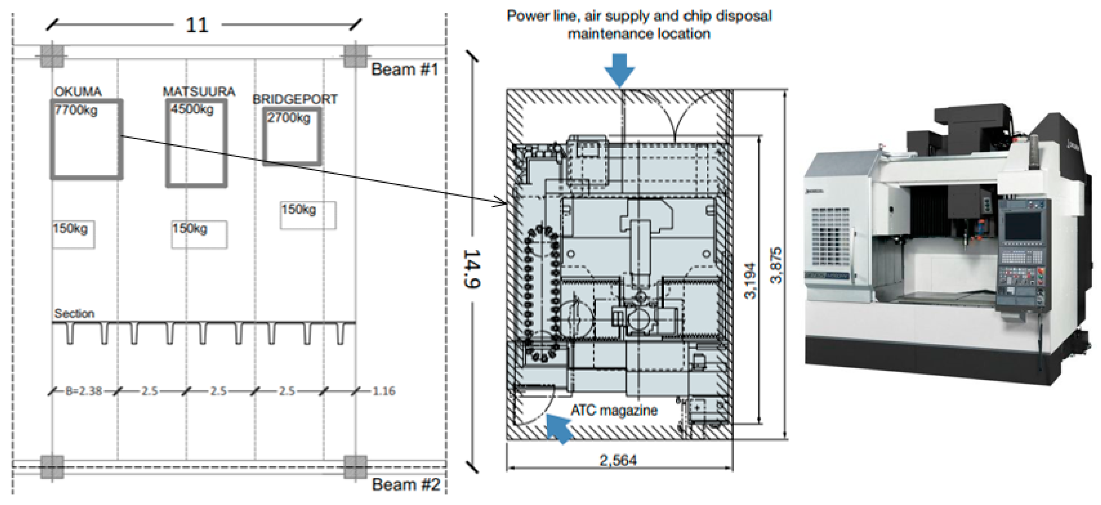
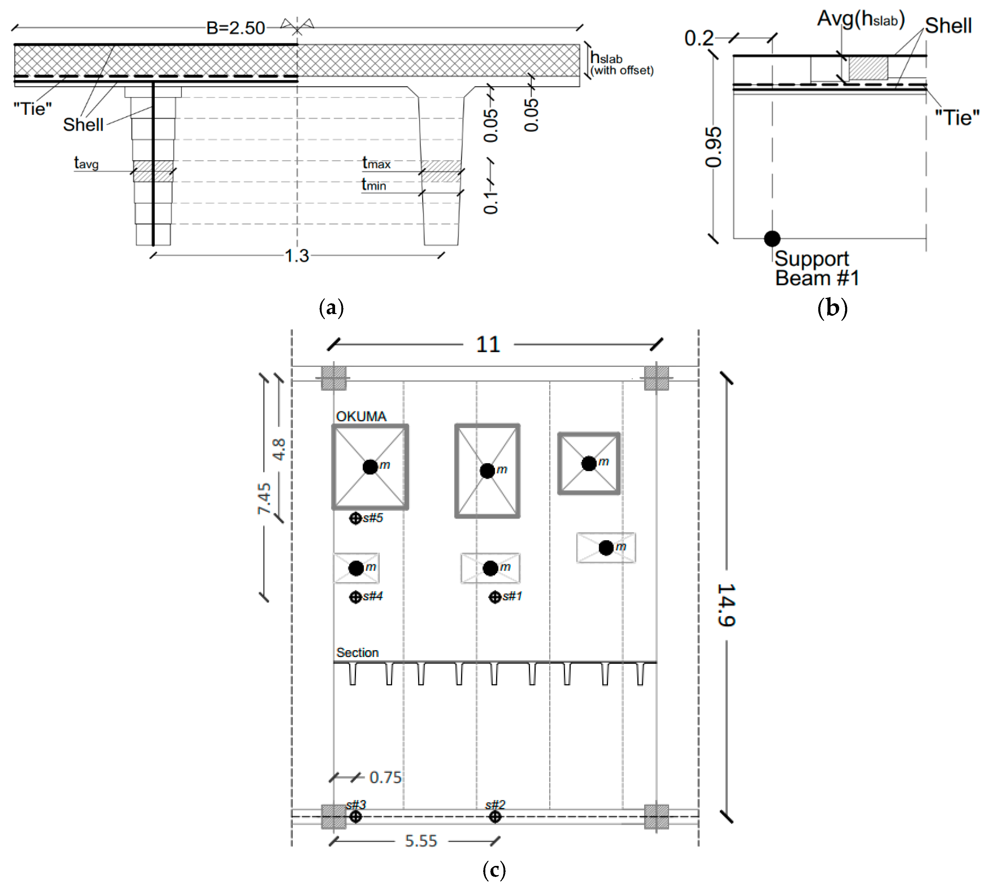
2.1. Case-Study Building

The production of optical glasses is based on various non-isolated CNC vertical machinery centers, as shown in Figure 3, that were mounted on the inter-story floor, with consequent severe resonance issues and management troubles for the factory.
The two-story, two-span, precast concrete building is in fact characterized by 13 m of elevation, with plan dimensions Lx = 67.1 × Ly = 30.8 m. The grid of beams and columns defines 6 × 2 adjacent bays (lx = 11 × ly = 14.9 m, for each one of them). The inter-story floor object of study is supported by plinth-restrained, square columns (80 × 80 cm their cross-section) and primary precast beams (spanning in the x direction) at 8 m from the foundation. These beams cover a total span of 10.25 m, with 0.2 m the width of cantilever supports that are offered by the columns.
The inter-story floor consists of a series of adjacent, unconnected double tee modular units and a continuous, cast-in-situ concrete slab on their top, that ensures the structural continuity and a certain flexural/torsional rigidity for the diaphragm. The double tee elements have cross-section features that agree with Figure 3b. The nominal height is h = 0.8 m, while the width B is equal to 2.34 m, 2.50 m or 2.55 m. The distance of the webs (b = 1.3 m) and the thickness of the top cap (hcap = 0.05 m) are indeed kept fix. The double tee elements are characterized by high slenderness, given that they are simply supported over L = 14.62 m of span.

2.2. CNC Machines

The selected floor region object of study is composed of five modular units (Figure 4) and hosts three non-isolated machines. The schematic plan view of Figure 4 shows their footprint and layout.
The equipment, more in detail, includes an OKUMA—GENOS M560-V-e vertical machinery tool [24] with total mass MOKUMA = 7700 kg (and Mspindle = 400 kg for the movable components) that roughly corresponds to ≈1/3 the mass of the supporting module. Additional superimposed permanent loads are represented by MATSUURA [25] and BRIDGEPORT [26] machines (4500 kg and 2700 kg respectively) and the corresponding equipment (≈150 kg/machine).

2.3. Experimental Methods

A series of on-site dynamic experiments was carried out on the inter-story floor region in Figure 4, to explore its dynamic performance under the working CNC machines. In total, 12 machinery/floor measurements were acquired from different configurations (by varying the reference machine, the assigned working process, the layout of instruments for the measurement of accelerations). Major outcomes are discussed in Section 3 and [13].

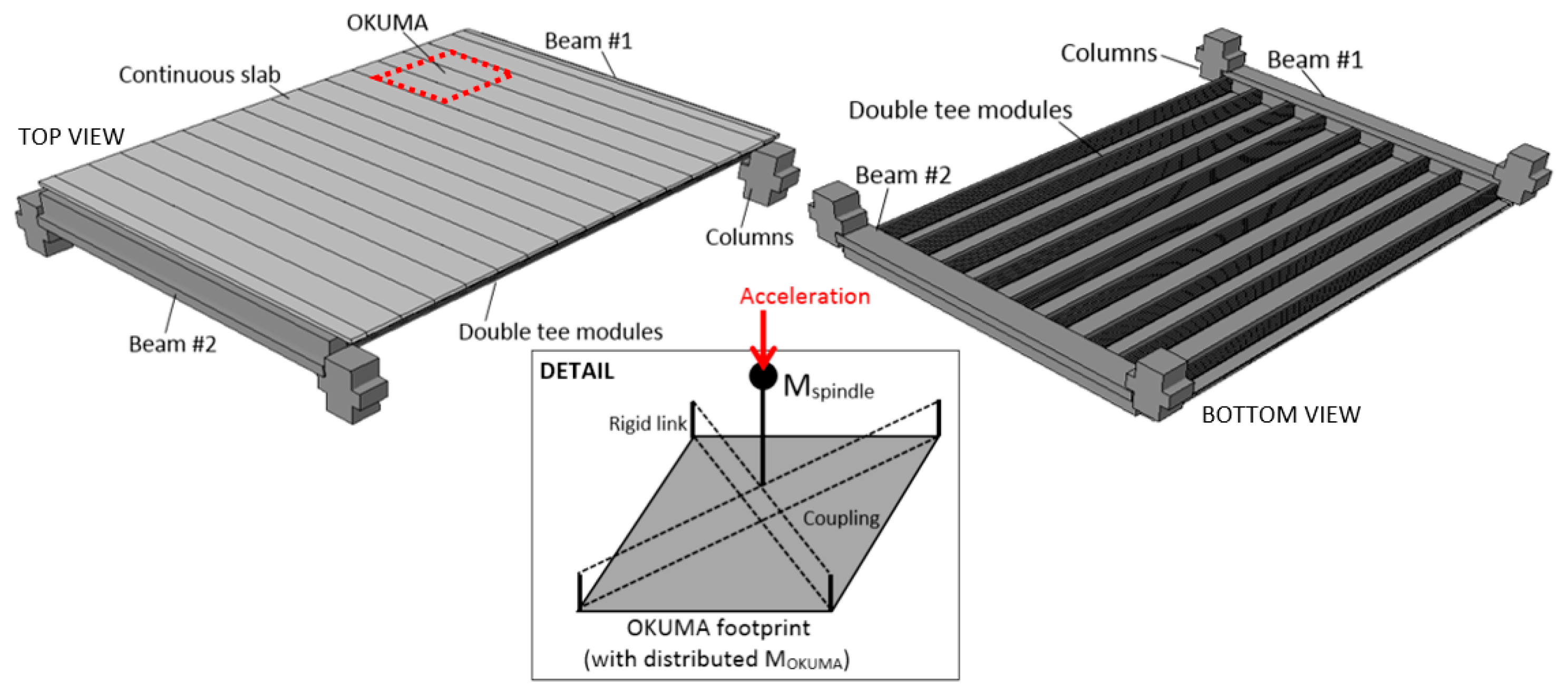
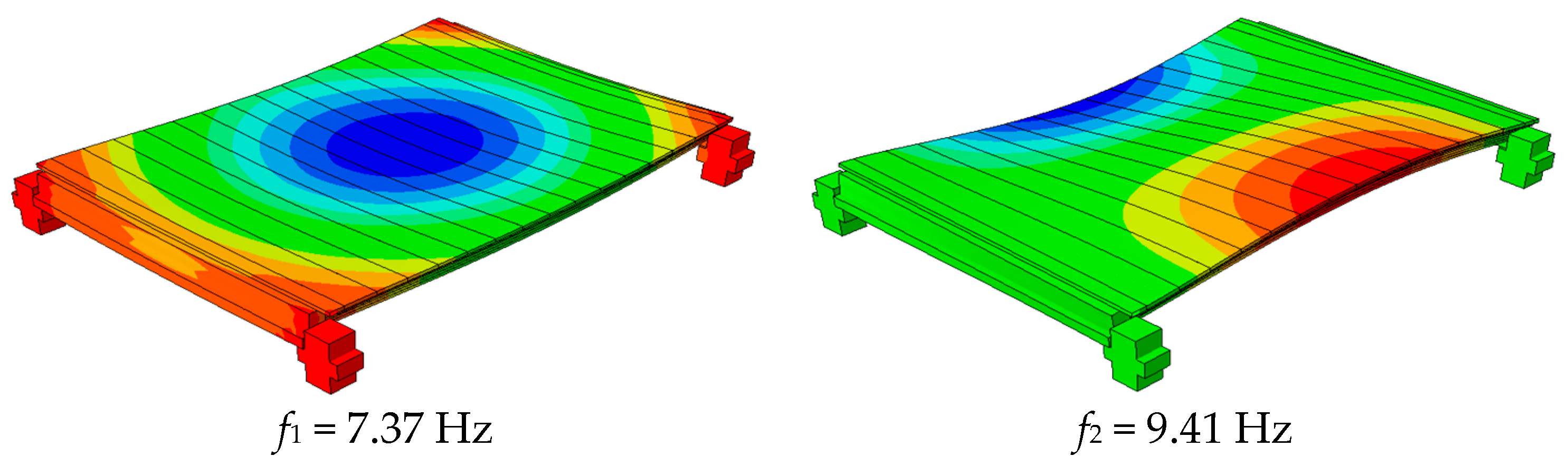
2.4. Finite Element Numerical Model

An extended numerical analysis was carried out in ABAQUS/Standard, based on a geometrically simplified but accurate FE model, that was validated to capture the vibrational response of the inter-story floor [13]. The selected floor region in Figure 4 was thus described, at the local level, with appropriate boundaries and kinematic constraints. S4R shell elements were used for the double tee modules (Figure 5). In the case of the webs, 0.1 m high shell elements with average thickness were used, while the slab was described with S4R elements and offset. A variable shell thickness was used along the span (0.2 m long segments), to account for the slab geometry. A distributed “tie” constraint was used between the precast and cast-in-situ shell elements. The floor region was thus assembled through adjacent precast modules and a continuous slab, but also including the supporting beams and columns (Figure 5 and Figure 6). The 3D solid elements were used for them, to account for their restraint effect on the floor. Each precast web was thus locally connected to the beams with a shell-to-solid constraint. Additional boundaries were defined along the slab edges, due to continuity.
Regarding the machines schematized in Figure 5c, a mixed approach was taken into account. A series of distributed masses was first used to reproduce the actual position of the sustained weights. In the case of the OKUMA machine, see Figure 6, an additional lumped term (Mspindle) with a rigid link was used for the spindle movements.
In this manner, the analysis was focused both on the prediction of the natural vibration modes of the floor (that can be affected by the masses of the machines at rest), as well as on the additional dynamic effects deriving from the operative OKUMA center. The input acceleration was hence derived from MEMS acquisitions on the machine.

3. Discussion of Results

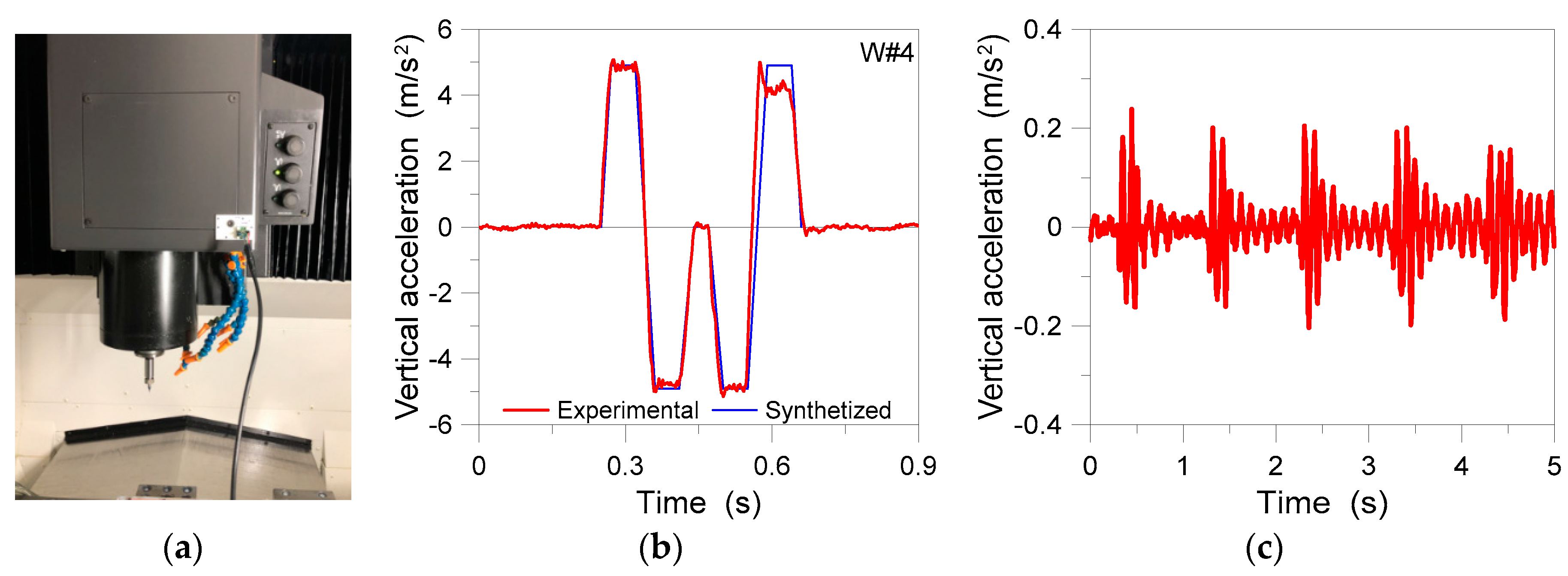
3.1. CNC Machinery Center and Inter-Story Floor Measurements

Under the typical operational conditions for the eyewear factory object of study, the spindle in Figure 7a was found subjected to cyclic vertical displacements and accelerations that are directly transferred to the supporting floor (non-isolated base restraints). During the field experiments, careful attention was thus paid to capture the key features of the input vibrational source. Such a goal was achieved with the support of a digital tri-axial accelerometers (ADXL355 type) that was mounted on the moving spindle. Among the various working programs of the OKUMA machine, the worst operational condition was taken into account for the analysis of the inter-story floor, and thus for the validation of the coupled experimental-numerical procedure. The corresponding acceleration-time history is shown in Figure 7b.
In parallel, additional experimental records were collected for the inter-story floor, with a digital tri-axial accelerometer (ADXL355 type) that was variably positioned on the floor region object of study (s#n labels in Figure 5c), under the effects of the working OKUMA. An example is proposed in Figure 7c, with evidence of the first five seconds of measurements, as obtained from the sensor s#4. The vertical acceleration peak was measured in 0.26 m/s2. From the post-processing stage of test measurements, moreover, the first two fundamental vibration frequencies of the floor were detected in the order of f1,exp = 7.4 Hz and f2,exp = 9.4 Hz.

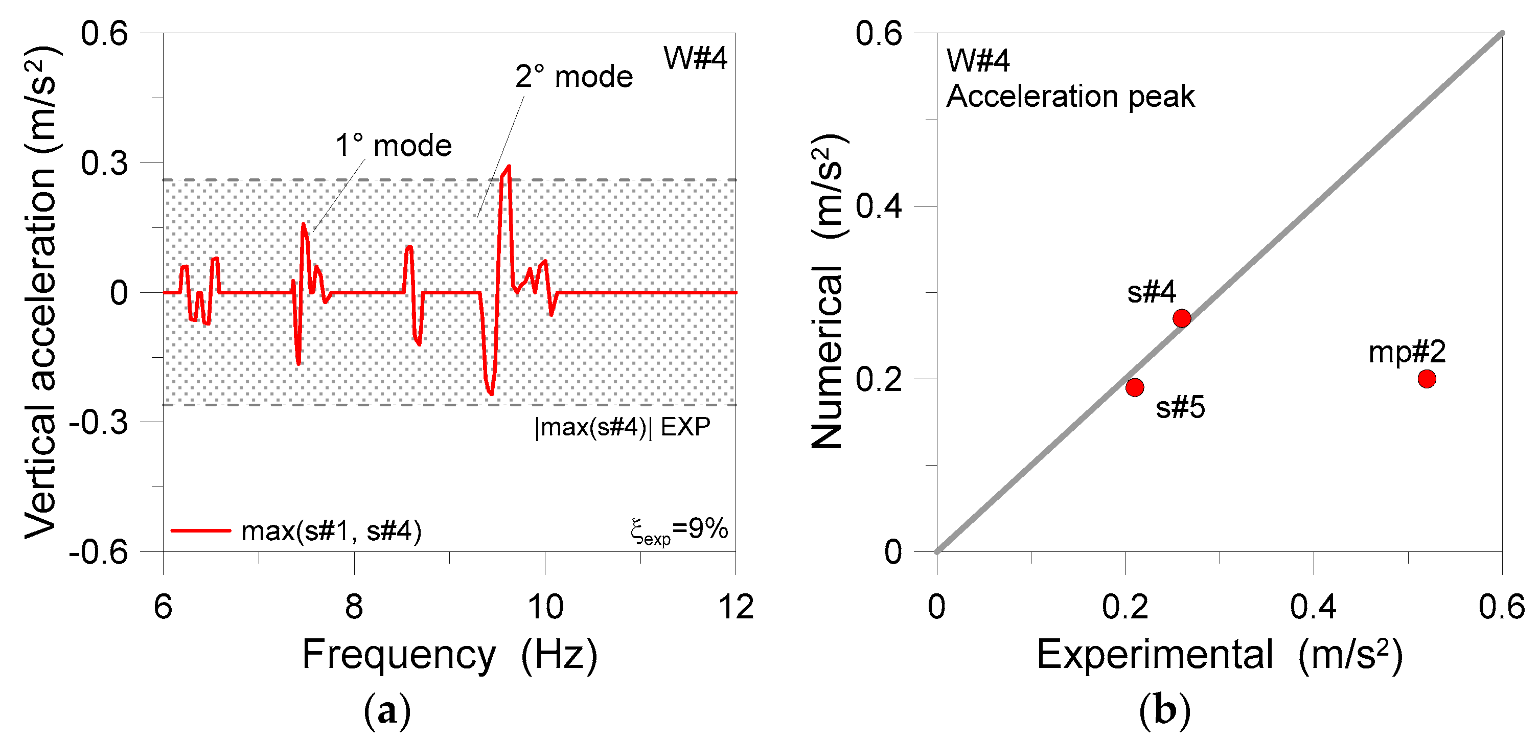
3.2. Validation of the Coupled Experimenta-Numerical Procedure

A linear “frequency” analysis was first carried out on the floor with the sustained masses only of the CNC machines at rest. The lower fundamental modes are proposed in Figure 8 and are typically associated, as also expected, to a global plate bending deformation of the whole inter-story floor. This is also confirmed by the validation of the one-bay FE model towards a more extended and geometrically complex FE model of the same structure [13].
Worth of interest from Figure 8 is the good correlation of the numerically predicted frequencies with the experimental derived frequencies of the floor (with f1,exp = 7.4 Hz and f2,exp = 9.4 Hz respectively). Moreover, from the FE analysis of the structure with the CNC machines at rest, the total machinery mass was found responsible of a −6% variation for the calculated lower frequencies (with f1,empty = 7.81 Hz and f2,empty = 9.98 Hz).
The conventional Steady State Dynamics (SSD) analysis was successively carried out on the FE model of Figure 6, under the W#4 cyclic input vibrations. In doing so, a total damping ξexp = 9% was taken into account for the analyses, based on the experimental feedback [13].
Major FE outcomes and selected SSD results are proposed in Figure 9. More in detail, the estimated SSD acceleration a velocity of the floor is shown in Figure 9a as a function of the frequency of the system, with a focus on the s#1 and s#4 numerical estimates, compared to the s#4 experimental peak. The confirmation that the structure suffers for marked resonance issues in the W#4 setup can be noticed in Figure 9a for the range of the examined natural frequencies of the floor. Moreover, the s#4 control point and the second mode of vibration of the structure were usually found to be associated with more pronounced dynamic effects, compared to the central s#1 point, as a result of the machine-induced vibrations and the related torsional deformations of the deck.
Figure 9b shows the experimental and FE numerical acceleration peaks from the same SSD analysis, as far as the s#4, s#5, and mp#2 control point are taken into account. It is possible to see a rather close correlation of measurements on the side of the floor, while the rigid link-based mechanical system in Figure 5 tends to underestimate the corresponding experimental measurement, due to the lack of detailing on the side of machinery components. In this regard, it is important to remind that the goal is to assess the effects of input machinery vibrations on the primary structure—and that the coupled procedure properly captures—rather than the local characterization of the machinery components. Further operational conditions and influencing parameters are hence discussed in [13].

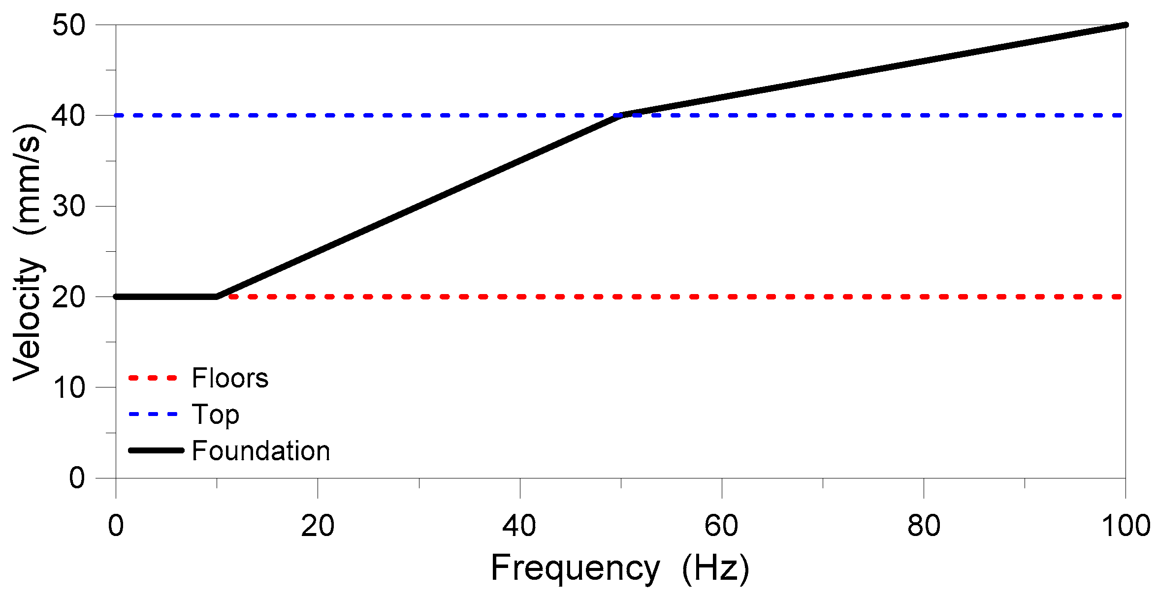
3.3. Vibration Serviceability Assessment

The refined structural FE model of the floor was used for additional comparative studies and vibration serviceability analyses [13]. In this regard, Figure 10 shows the acceleration, velocity and displacement peaks for the W#4 program, as a function of the FE input parameters for concrete (MoE) and damping. As known, the availability of reliable FE estimates represents a strategic feedback in support of the early design stage of buildings (and thus a crucial input for the original design of the case-study factory), and thus an important outcome that suggests the predictivity of possible vibration issues. Figure 10 gives evidence (for the W#4 process) of “experimental” and “design” modeling assumptions for the investigated floor. Worth of interest the remarkable scatter of the collected numerical predictions, as a function of the input parameters. The “design” W#4 velocity estimates, more in detail, were found to roughly approach the reference velocity limit of 20 mm/s for structural damage prevention, thus representing a potential early warning for the overall design process. From the vertical displacements of the floor, see Figure 10c, the corresponding DAF was calculated up to +6.2 for the W#4 program, thus representing another early warning parameter to account in preliminary design decisions.

4. Conclusions

The prediction of machine-induced vibrations is a key step for the early design stage. However, the description of the vibration source, as well as the reliability of the available structural models, can be challenging. In this paper, a case-study eyewear factory was investigated, with a focus on the vibration issues of its floor, where non-isolated CNC machines were mounted. An experimental characterization of the machinery activity was presented. The reliable FE analysis of the floor was thus carried out with realistic input excitations. The good match of field and numerical predictions confirmed the added value of coupled experimental-numerical predictive studies, so as to prevent (or mitigate) possible machine-induced vibrational issues.

Author Contributions

This research paper results from a joint collaboration of all the involved authors. E.B. and M.F. handled the field experimental analysis and post-processing stage, while C.B. took care of the numerical analysis. All the authors contributed to the discussion and analysis of comparative results, and thus to the drafting of the final document. All authors have read and agreed to the published version of the manuscript.

Acknowledgments

The IECAT2020 (1st International Electronic Conference on Actuator Technology: Materials, Devices and Applications) Organizing Team, the Conference Chairs and Committee are acknowledged for the interest and positive evaluation of the submitted research topic.

Conflicts of Interest

The authors declare no conflict of interest.

Abbreviations

The following abbreviations are used in this manuscript:
CNCcomputer numerical control
DAFdynamic amplification factor
FEfinite element
MEMSmicro electro-mechanical systems
MoEmodulus of elasticity

References

  1. Bachmann, H.; Ammann, W. Vibrations in Structures Induced by Man and Machines; IABSE-International Association for Bridge and Structural Engineering: Zurich, Switzerland, 1987; ISBN 3-85748-052-X. [Google Scholar]
  2. Feldmann, M.; Heinemeyer, C.; Butz, C.; Caetano, E.; Cunha, A.; Galanti, F.; Goldack, A.; Hechler, O.; Hicks, S.; Keil, A.; et al. Design of Floor Structures for Human Induced Vibrations; Technical Report EUR 24084 EN; Publications Office of the European Union: Bruxelles, Belgium, 2009; ISBN 978-92-79-14094-5. [Google Scholar] [CrossRef]
  3. Da Silva, J.G.S.; Sieira, A.C.C.F.; Da Silva, L.A.P.S.; Rimola, B.D. Dynamic Analysis of Steel Platforms When Subjected to Mechanical Equipment-Induced Vibrations. J. Civ. Eng. Arch. 2016, 10, 1103–1113. [Google Scholar] [CrossRef]
  4. Brownjohn, J.; Pavic, A. Vibration control of ultra-sensitive facilities. Proc. Inst. Civ. Eng. Struct. Build. 2006, 159, 295–306. [Google Scholar] [CrossRef]
  5. Chang, M.-L.; Lin, C.-C.; Ueng, J.-M.; Hsieh, K.-H.; Wang, J.-F. Experimental study on adjustable tuned mass damper to reduce floor vibration due to machinery. Struct. Control Health Monit. 2009, 17, 352–548. [Google Scholar] [CrossRef]
  6. Kazantzi, A.K.; Vamvatsikos, D. Seismic and Vibration Performance Rehabilitation for an Industrial Steel Building. Pract. Period. Struct. Des. Constr. 2020, 25, 05020001. [Google Scholar] [CrossRef]
  7. Wilson, R.R. Machine Foundations. In Vibrations of Engineering Structures; Lecture Notes in Engineering; Springer: Berlin/Heidelberg, Germany, 1985; Volume 10. [Google Scholar] [CrossRef]
  8. Tian, Y.; Liu, Z.; Xu, X.; Wang, G.; Li, Q.; Zhou, Y.; Cheng, J. Systematic review of research relating to heavy-duty machine tool foundation systems. Adv. Mech. Eng. 2019, 11. [Google Scholar] [CrossRef]
  9. Stimac, G.; Braut, S.; Zigulic, R. Structural optimization of turbine generator foundation with frequency constraint. Strojarstvo 2011, 53, 389–398. [Google Scholar]
  10. Liu, J.B.; Wang, Z.Y.; Zhang, K.F.; Pei, Y.X. 3D Finite element analysis of large dynamic machine foundation considering soil-structure interaction. Eng. Mech. 2002, 19, 34–35. [Google Scholar]
  11. Tian, Y.; Shu, Q.; Liu, Z.; Ji, Y. Vibration Characteristics of Heavy-Duty CNC Machine Tool-Foundation Systems. Shock Vib. 2018, 2018. [Google Scholar] [CrossRef]
  12. Werner, U. Derivation of a plane vibration model for electrical machines on soft machine foundations. Forsch. Ing. 2010, 74, 185–205. [Google Scholar] [CrossRef]
  13. Bergamo, E.; Fasan, M.; Bedon, C. Efficiency of Coupled Experimental–Numerical Predictive Analyses for Inter-Story Floors Under Non-Isolated Machine-Induced Vibrations. Actuators 2020, 9, 87. [Google Scholar] [CrossRef]
  14. ABAQUS Computer Software; Simulia: Providence, RI, USA, 2020.
  15. Bedon, C.; Bergamo, E.; Izzi, M.; Noé, S. Prototyping and Validation of MEMS Accelerometers for Structural Health Monitoring-The Case Study of the Pietratagliata Cable-Stayed Bridge. J. Sens. Actuator Netw. 2018, 7, 30. [Google Scholar] [CrossRef]
  16. Brand, T. Demands on Sensors for Future Servicing: Smart Sensors for Condition Monitoring. 2017. Available online: https://www.analog.com/media/en/technical-documentation/tech-articles/A60151-Demands-on-Sensors-for-Future-Servicing-Smart-Sensors-for-Condition-Monitoring.pdf (accessed on 7 November 2020).
  17. Cizikova, A.; Monkova, K.; Monka, P.; Moravec, M. Analysis of frequency characteristics at spindle of CNC machining centre. MM Sci. J. 2016, 2016, 1515–1518. [Google Scholar] [CrossRef]
  18. Abdulhani, F.; Alswede, J. Study of vibration for CNC machine at different feed. Int. J. Adv. Res. Technol. 2014, 3, 21–29. [Google Scholar]
  19. Dogrusoz, H.; Wszolek, G.; Czop, P.; Sloniewski, J. Vibration monitoring of CNC machinery using MEMS sensors. J. Vibroeng. 2020, 22, 735–750. [Google Scholar] [CrossRef]
  20. Eurocodice 4—Progettazione Delle Strutture Composte Acciaio-Calcestruzzo-Parte 1-1: Regole Generali e Regole per Gli Edifici; UNI EN 1994-1-1:2004; Ente Nazionale Italiano di Unificazione (UNI): Milan, Italy, 2005.
  21. Ministero delle Infrastrutture e dei Trasporti-DM 17/01/2018. Norme Tecniche per le Costruzioni (NTC2018). 2018.
  22. Ministero delle Infrastrutture e dei Trasporti-Circolare n.7 del 21/01/2019-Istruzioni per l’applicazione dell’ “Aggiornamento delle Norme Tecniche per le Costruzioni”. 2019.
  23. Criteri di Misura e Valutazione Degli Effetti Delle Vibrazioni Sugli Edifici; UNI9916: 2014; Ente Nazionale Italiano di Unificazione (UNI): Milan, Italy, 2014.
  24. OKUMA Europe GmbH. Available online: www.okuma.eu (accessed on 27 July 2020).
  25. MATSUURA Machinery Corporation. Available online: https://www.matsuura.co.jp/english/ (accessed on 27 July 2020).
  26. BRIDGEPORT Machines. Available online: https://www.hardinge.com/product-brand/bridgeport/ (accessed on 27 July 2020).
Figure 1. Vibration monitoring for machines: (a) typical setup and (b) schematic representation of machine life cycle assessment (adapted from [16]).
Proceedings 64 00015 g001
Figure 2. Reference velocity peak limits to prevent structural damage in industrial buildings exposed to short-term vibrations.
Proceedings 64 00015 g002
Figure 3. Reference modular unit for the inter-story floor under investigation: (a) general view, with evidence of computer numerical control (CNC) machines and equipment, and (b) transversal cross-section (dimensions in m).
Proceedings 64 00015 g003
Figure 4. Plan view of the floor region of study (dimensions in m), with details of the CNC machines.
Proceedings 64 00015 g004
Figure 5. Modelling of the modular elements: (a) cross-section (example for B = 2.5 m) and (b) side view, with (c) final layout of the assembled floor region (plan view). All dimensions in m.
Proceedings 64 00015 g005
Figure 6. Layout of the Finite Element (FE) model for the area of investigation of the inter-story floor (ABAQUS/Standard).
Proceedings 64 00015 g006
Figure 7. Experimental outcomes: (a) detail of the OKUMA moving spindle, with (b) derivation of the synthetized signal (single cycle) and (c) corresponding vertical acceleration of the floor (s#4) under the worst operational condition.
Proceedings 64 00015 g007
Figure 8. Numerical derivation of the fundamental vibration modes of the floor with CNC machines at rest (ABAQUS/Standard).
Proceedings 64 00015 g008
Figure 9. Steady State Dynamics (SSD) analysis of the inter-story floor region with the working OKUMA (ABAQUS/Standard, one-bay FE model, W#4). Evolution of (a) vertical acceleration peaks in the s#1 and s#4 control points, with (b) comparison of absolute acceleration peaks for the W#4 experimental configuration (SSD analyses based on the OKUMA synthetized signal).
Proceedings 64 00015 g009
Figure 10. SSD analysis of the inter-story floor region with the working OKUMA (ABAQUS/Standard, one-bay FE model, W#4): (a) vertical acceleration, (b) velocity, and (c) displacement peaks in the s#1 and s#4 control points, as a function of the dynamic MoE of concrete (nominal vs. experimental) and damping (nominal vs. experimental).
Proceedings 64 00015 g010
Publisher’s Note: MDPI stays neutral with regard to jurisdictional claims in published maps and institutional affiliations.

