Proceeding Paper

Porphycene Films Grown on Highly Oriented Pyrolytic Graphite: Unveiling Structure–Property Relationship through Combined Reflectance Anisotropy Spectroscopy and Atomic Force Microscopy Investigations †

1
Consiglio Nazionale delle Ricerche, Istituto di Scienze e Tecnologie Chimiche “G. Natta” (CNR-SCITEC) and SmartMatLabCenter, via Fantoli 16/15, 20138 Milan, Italy
2
Department of Physics, Politecnico di Milano, p.za Leonardo da Vinci 32, 20133 Milan, Italy
3
Faculty of Mathematics and Science, Cardinal Stefan Wyszyński University, Dawajtis 5, 01-815 Warsaw, Poland
4
Institute of Physical Chemistry, Polish Academy of Sciences, Kasprzaka 44, 01-224 Warsaw, Poland
5
Department of Earth and Environmental Sciences, Università degli Studi di Milano-Bicocca, p.za della Scienza 4, 20126 Milan, Italy
*
Authors to whom correspondence should be addressed.
Presented at the 4th International Conference nanoFIS 2020—Functional Integrated nano Systems, Graz, Austria, 2–4 November 2020.
Proceedings 2020, 56(1), 44; https://doi.org/10.3390/proceedings2020056044
Published: 3 March 2021

Abstract

:
Thin organic films are widely used in sensors, solar cells, and optical devices due to their intense absorption in the visible/near-infrared (IR) region. Shifting, quenching, or reshaping of some spectral features can be achieved by chemical functionalization of the molecules, whereas an anisotropic fingerprint due to preferential molecular alignment can be induced via a proper design and/or preparation of the substrate. Recently, we investigated the optical response of thin films of porphycene to acidification. With respect to the well-known and closely related tetraphenyl porphyrin, porphycene has the clear advantage of being optically active in the full visible range, and this makes visible by naked eye the immediate change of the film from brilliant blue-turquoise to green when exposed to HCl vapors. In this work, by exploiting a homemade reflectance anisotropy spectroscopy (RAS) apparatus, we explore possible optical anisotropies in the visible spectral range of porphycene films and relate them to the film morphology analyzed by atomic force microscopy (AFM).

1. Introduction

Organic molecules are employed in many devices such as sensors [1,2], photovoltaic systems [3,4,5], and electronic circuits [6,7,8]. The advantage of their use over other systems is related to the presence of many synthetic tools that allows for the tuning of their physical and chemical properties [9]. In this respect, the absorbance spectral range can be widely tuned to match, e.g., the solar spectrum, or the gap between the highest occupied molecular orbital and the lowest unoccupied one (HOMO-LUMO) can be expanded or shrunk for optimizing the band alignment and the electron transfer at the heterorganic interfaces [10,11,12]. Heterocyclic organic molecules offer the possibility of exploiting intramolecular mechanisms, potentially leading to compounds suitable for single-molecule devices, as recently proposed for switches [13]. In this case, the possible interconversion of tautomers (i.e., constitutional isomers) in a free-base tetraphenyl porphyrin (H2TPP) molecule is suggested as a working principle of an electronic device. We proposed a simple preparation to align and stabilize an array of H2TPP tautomers along a preferential direction, when deposited on highly oriented pyrolytic graphite (HOPG) [14]. This result represents an obligatory step for the construction of scalable devices. Ordered arrays of tautomers can be monitored by traditional optical spectroscopies, such as reflectance anisotropy spectroscopy (RAS), opening the route toward possible optical device prototypes.
However, the main H2TPP absorption peak is centered at around 420 nm, and changes in the optical properties can only be detected by probing at this wavelength. Recently, we started a comparative investigation of the assembling and optical properties of H2TPP and porphycene (H2Po) when grown on HOPG [15]. H2Po, whose structure is reported in Figure 1, shows intense adsorption features at both the main Soret region (358 nm) and the Q-band region (between 558 nm and 630 nm), which lend a brilliant blue color to the deposited films. In addition, the exposure of H2Po to acid vapors suddenly converts the film color from blue to green (H2Po protonation), according to the over 60 nm red shift of the Soret bands and the reduced absorption of the Q transitions. The optical activity in the red part of the visible range makes H2Po extremely interesting for sensor and device application.
From a morphological point of view, thin H2Po films show crystals placed on a two-dimensional (2D) wetting layer [15] undergoing clear damage when the film is exposed to acid vapors (namely, hydrochloric acid, HCl), in close agreement with that observed in H2TPP samples [12].
In this work, we complete the comparison between H2TPP and H2Po films on HOPG by studying the optical anisotropy of the porphycene films in the visible spectral range (L-bands). In fact, when applied to porphyrin samples, RAS was able to disclose important information on the assembling properties of the molecules and to bridge the data acquired on the mesoscopic and microscopic length scale [16]. Here, we prove that the H2Po and H2TPP wetting layers on HOPG show an optical anisotropy that is maximized (in modulus) along the same direction.

2. Materials and Methods

H2Po was obtained from 2,7,12,17-tetra-tert-butylporphycene using a previously reported procedure [17]. Porphycene films were grown by physical vapor deposition (PVD) at a base pressure of 5 × 10⁻⁶ mbar. The growth chamber (Kenositec KE500) was provided with four Knudsen cells (K-cell). The sample holder was positioned at about 30 cm away from the K-cells. The latter were thermally controlled via a thermocouple. H2Po was sublimated under high-vacuum conditions at around 220 °C. Highly oriented pyrolytic graphite (α-grade HOPG, Optigraph 1 cm × 1 cm) was exfoliated with an adhesive tape before any molecule deposition. HOPG substrates were kept at room temperature during the molecule deposition. A quartz microbalance was placed close to the sample to monitor the molecular deposition rate (0.3–0.4 Å/s), allowing the nominal film thickness evaluation, which is defined as the final thickness displayed by the quartz crystal microbalance. The latter was previously calibrated by comparing the nominal thickness of thicker samples by means of a capacitive profilometer.
The organic films were also exposed to vapors of hydrochloric acid. The latter were produced by dropping sodium chloride inside concentrated sulfuric acid (>98%, provided by Merck). In this way, a huge amount of vapors can reach the sample, and the protonation is ensured on the whole sample surface.
A homemade RAS setup was used for the experiments. Details of our system were reported in the literature [18]. Our optical setup works in the visible spectral range. RAS spectra were here collected between 500 nm and 630 nm where the Q-bands are located. The light spot on the sample was about 1 mm2.
The RAS signal is defined as
Δ R R = 2 R α R β R α + R β
where Rα(β) is the reflectivity of light polarized along the α(β) direction. When used to study single crystals, α(β) is aligned along a high-symmetry direction. Conversely, when organic films are investigated by RAS, the maximum anisotropy is not known a priori, and an azimuthal analysis must be performed. In this case, the sample is rotated around the substrate surface normal axis, and spectra are acquired and plotted in a polar plot (see below).
A commercial atomic force microscope (AFM, Keysight 5500) was employed for the microscopic morphological characterization. Images were collected in tapping mode to prevent the organic film from possible damages. We used silicon tips (NanoSensors) with an apex curvature of about 20 nm and a resonance frequency of 310 kHz.

3. Results and Discussion

3.1. Optical Characterization and the Effect of the Exposure to Acid Vapors

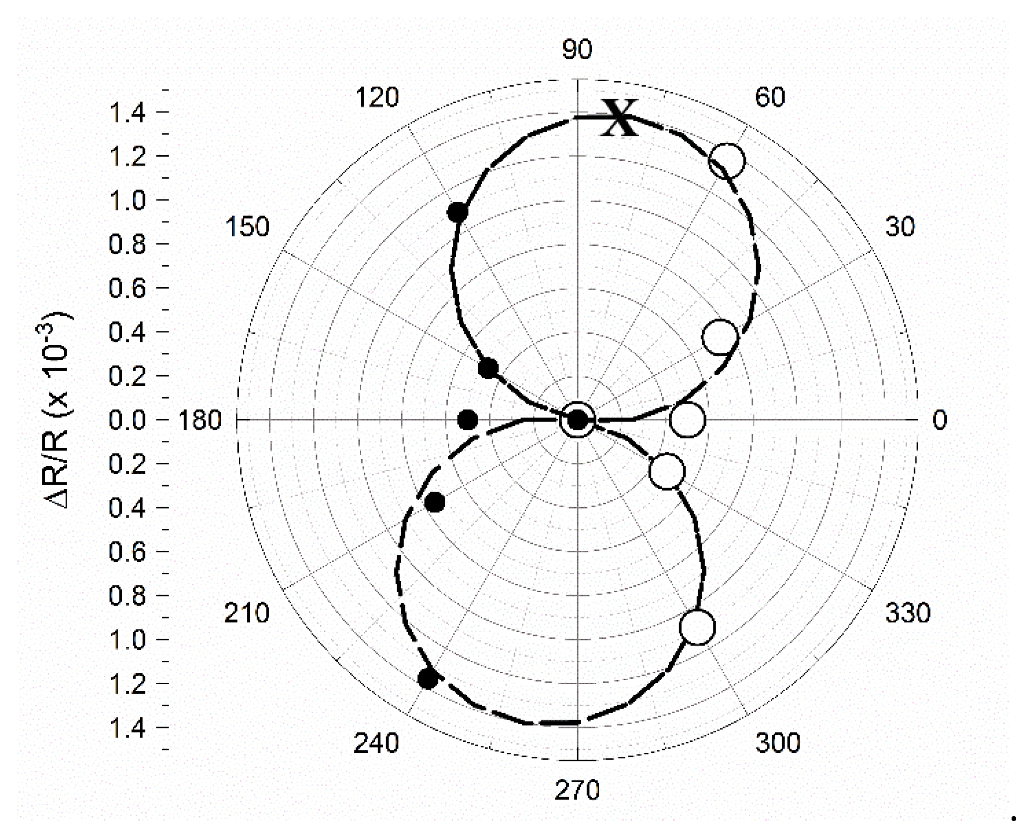
A sample of H2Po with a nominal thickness of 10 nm, directly comparable with the one used in a previous work [15], was analyzed by RAS in view of finding the maximum anisotropic signal. The sample was rotated around the substrate surface normal axis with 30° steps, and a spectrum was collected at each step (see Figure 2). The RAS intensity of a peak at around 600 nm is reported as a function of the azimuthal angle θ. The latter represents the angle between a RAS polarization direction (α) and the exfoliation direction used for the HOPG preparation.
Using linearly polarized light, an overall azimuthal rotation of 180° is enough to find the maximum anisotropy direction at θ = 80°. These data are reported by open dots. The filled circles are placed at symmetrically equivalent azimuthal angles (θ’ = θ + 180°) only to help the reading of the expected theoretical behavior (dashed line). The latter follows the equation below [19].
Δ R R ( θ ) = Δ Δ R m a x ( cos 2 θ ) 2 .
We find the maximum intensity when the RAS α-polarization direction is aligned almost perpendicularly with respect to the HOPG exfoliation line. In H2TPP films, the maximization is achieved when the RAS α-polarization direction is parallel to the HOPG exfoliation line [20]. A theoretical investigation of the optical properties of porphyrins showed that RAS anisotropy is strictly related to the alignment of tautomers [16]. If we assume for H2Po the same interpretative picture (the optical transition along the NH–HN direction (see Figure 1) is placed at a larger wavelength), we can, thus, speculate that the tautomer preferential alignment is influenced by the graphite exfoliation.
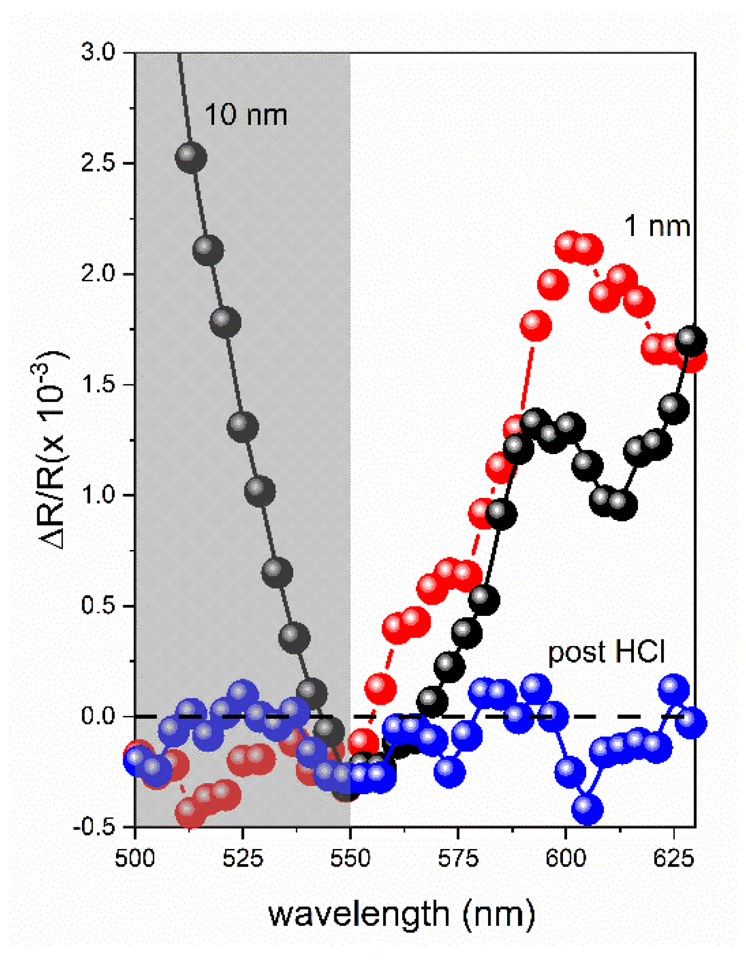
Figure 3 reports the maximized RAS spectra of the Q-bands for the 10 nm and 1 nm thick H2Po films on HOPG. Despite being 10 times thicker, the signal intensity of the former does not exceed that of the thinner sample. This suggests that the anisotropic character is immediately provided by the H2Po wetting layer. The presence of crystals on thicker samples mainly influences the Soret band located in the ultraviolet (UV) spectral range. This fact can be deduced from the significant enhancement of the RAS signal below 500 nm (shaded area in the Figure 3).
After the exposure to HCl vapors, the 10 nm thick sample is significantly altered in its optical anisotropic properties (blue dots). We previously reported the protonation effect on the absorption and reflection properties of the H2Po film [15]. In that investigation, we observed a recovery, at least partial, of the studied optical properties. In this case, the anisotropic RAS signal of the Q-bands is irreversibly quenched. It is known that H2Po protonation is not stable in time but, in a few seconds, the HCl excess is removed from the sample. Consequently, we speculate that the original molecular assembly is definitively lost, probably due to the intense exposure to acid vapors. This question can find an answer only by future scanning tunneling investigations.

3.2. Morphological Characterization and the Effect of the Exposure to Acid Vapors

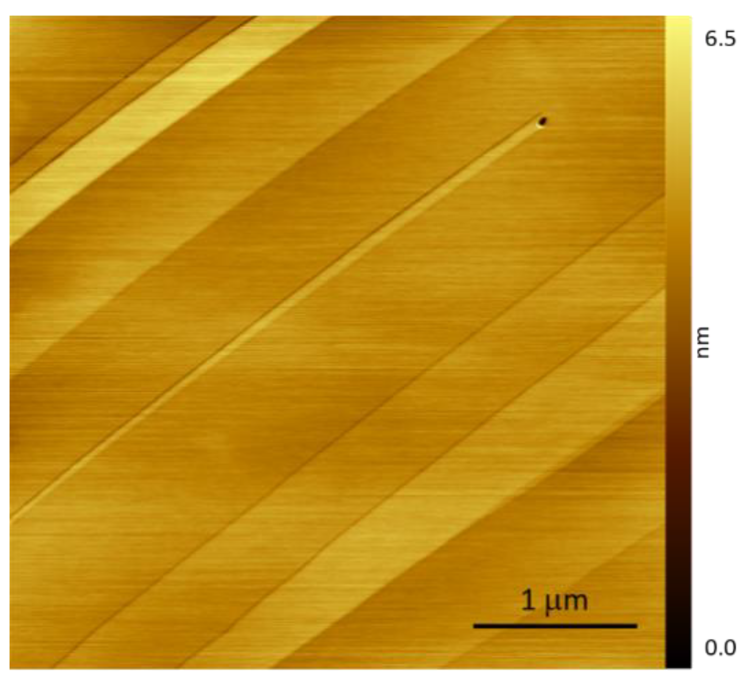
A freshly exfoliated graphite substrate generally shows a well-recognizable morphology where flat terraces are separated by mono- or multiatomic steps. An AFM characteristic image is reported in Figure 4.
The roughness value (here defined as the arithmetical mean deviation from the assessed profile, Ra) is about 0.1 Å, thus allowing to discern even a monoatomic step.
The morphology is similar when the 1 nm thick H2Po sample is analyzed (Figure 5a). No three-dimensional (3D) structures or crystals are visible, and graphite steps are still recognizable. Nonetheless, the Ra increases to about 0.3–0.5 Å, suggesting that something covers the graphite substrate. We observe that the phase contrast image (panel b) appears homogeneous. We conclude that the H2Po wetting layer is uniformly disposed on the HOPG substrate.
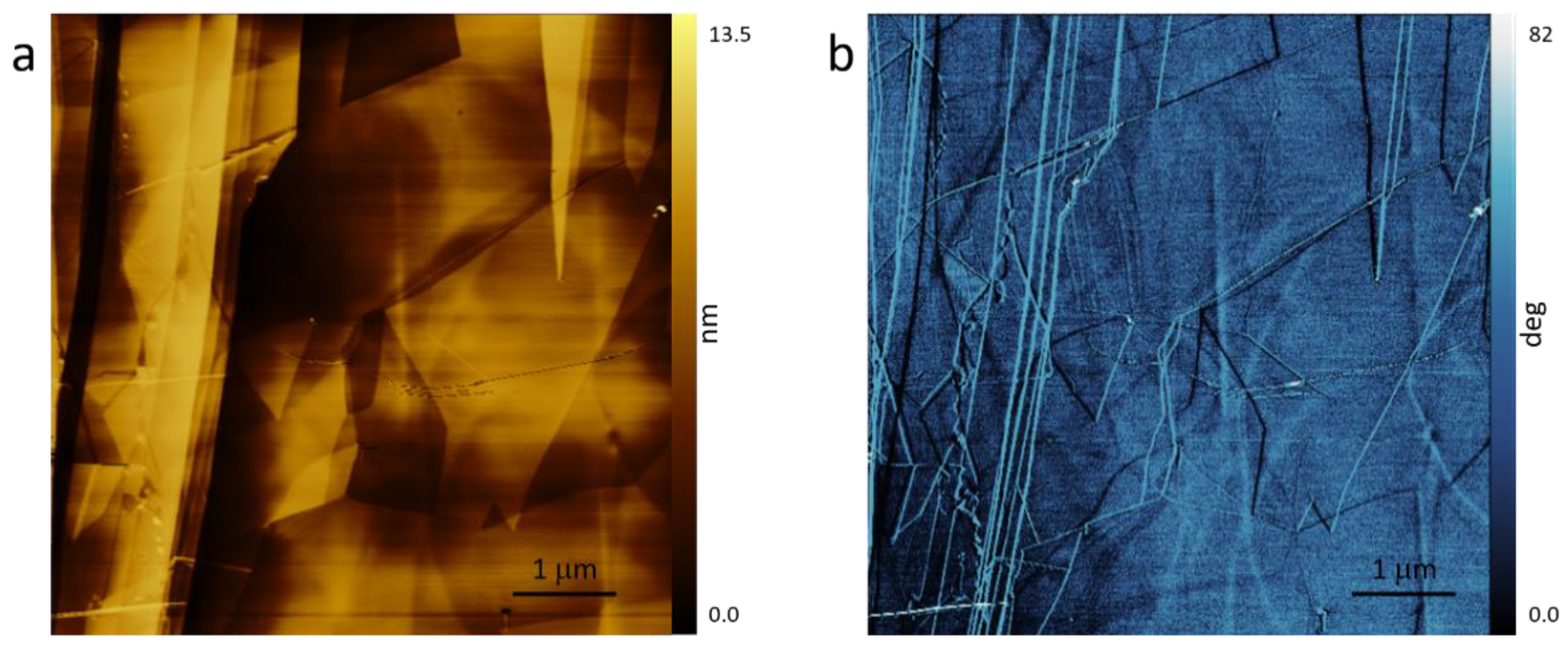
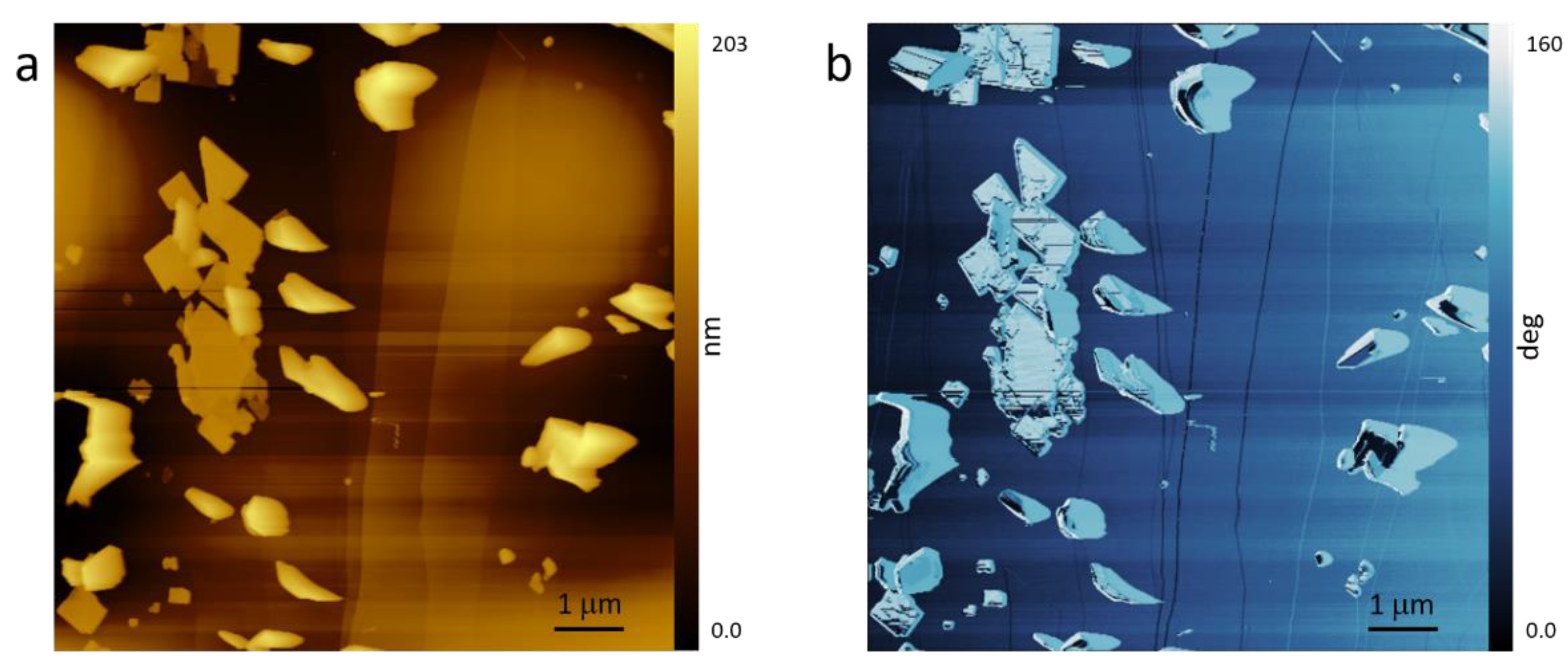
The 10 nm thick sample is instead characterized by crystals that evolve from the molecular wetting layer (Figure 6a).
They have different sizes and sharp edges. In panel b, we report the phase-contrast image where 3D structures are observed to give rise to bright regions distributed on a uniform darker background corresponding to the 2D wetting layer. This contrast suggests that crystals and the wetting layer have a substantially different molecular arrangement. This morphology is significantly altered after the exposure to HCl vapors. In this case, only few crystals (3D structures having sharp edges) are observed, while the topography is characterized by globular clusters (Figure 7a) in agreement with previous AFM investigations [14,16]. Conversely, with respect to the literature, the phase contrast image (see Figure 7b) does not really help here in recognizing different regions of covered or uncovered graphite areas. The topography results are, however, in agreement with the RAS analysis, suggesting a significant alteration of the assembling properties of the H2Po molecules.

4. Conclusions

Porphycene films were recently investigated due to their interesting optical properties in the visible spectral range when exposed to acid vapors. Starting from an intense blue color, the film suddenly becomes green during the molecular protonation. The recovery takes only a few seconds in standard conditions. In this work, we extend our comparison between porphyrin and porphycene films. By exploiting RAS spectroscopy, the authors have already proven that H2TPP anisotropic optical properties can bridge microscopic information (namely, tautomer alignment) to others on the mesoscopic scale. Consequently, a homemade RAS apparatus was employed to study H2Po films. Interestingly, we observe a small signal in the Q-band region of the molecules. Anisotropy is detected both on the wetting layer and on a thicker (10 times) film. The maximum anisotropy is found when the graphite exfoliation direction is almost aligned along the beta polarization axis. This means that molecules can be preferentially oriented along a direction that is known a priori. Despite this fact, other properties differentiate porphyrin and porphycene molecules. In particular, the Q-bands seem to be quenched after the exposure to acid vapors, suggesting some rearrangements of the assembled film.

Author Contributions

Conceptualization, G.B.; methodology, A.B.; software, L.F.; investigation, M.C.; sample preparation, M.P.; molecular synthesis, J.W.; writing—original draft preparation, F.C.; review and editing, L.D. All authors have read and agreed to the published version of the manuscript.
Funding: This study was funded by the University of Milano—Bicocca with FAQC grant n. 2018-ATESP-0010, the Polish National Science Center Grant No. 2017/26/M/ST4/00872, the Regione Lombardia and Fondazione CARIPLO (grant numbers 12689/13, 7959/13; Azione 1 e 2, “SmartMatLab centre” and Cariplo Foundation grant 2013-1766), and the Italian MUR under the project PRIN 2017 (grant n° 2017FJCPEX “3D-FARE: functional 3D architectures for electrochemiluminescence applications”.

Data Availability Statement

Data available on request.

Conflicts of Interest

The authors declare no conflict of interest.

References

  1. Li, H.-Y.; Zhao, S.-N.; Zang, S.-Q.; Li, J. Functional metal-organic frameworks as effective sensors of gases and volatile com-pounds. Chem. Soc. Rev. 2020, 49, 6364–6401. [Google Scholar] [CrossRef] [PubMed]
  2. Zhang, S.; Zhao, Y.; Du, X.; Chu, Y.; Zhang, S.; Huang, J. Gas sensor based on nano/microstructured organic field-effect tran-sistors. Small 2019, 15, 1805196. [Google Scholar] [CrossRef] [PubMed]
  3. Li, Y.; Guo, X.; Peng, Z.; Qu, B.; Yan, H.; Ade, H.; Zhang, M.; Forrest, S.R. Color-neutral, semitransparent organic photovoltaics for power window applications. Proc. Natl. Acad. Sci. USA 2020, 117, 21147–21154. [Google Scholar] [CrossRef] [PubMed]
  4. Xu, C.; Wang, J.; An, Q.; Ma, X.; Hu, Z.; Gao, J.; Zhang, J.; Zhang, F. Ternary small molecules organic photovoltaics exhibiting 12.84% efficiency. Nano Energy 2019, 66, 104119. [Google Scholar] [CrossRef]
  5. Kozma, E.; Kotowski, D.; Catellani, M.; Luzzati, S.; Cavazzini, M.; Bossi, A.; Orlandi, S.; Bertini, F. Design of perylene diimides for organic solar cell: Effect of molecular steric hindrance and extended conjugation. Mater. Chem. Phys. 2015, 163, 152–160. [Google Scholar] [CrossRef]
  6. Yumusak, C.; Sariciftci, N.S.; Irimia-Vladu, M. Purity of organic semiconductors as a key factor for the performance of organic electronic devices. Mater. Chem. Front. 2020, 4, 3678–3689. [Google Scholar] [CrossRef]
  7. Ji, D.; Hu, W.; Fuchs, H. Recent progress in aromatic polymide dielectrics for organic electronic devices and circuits. Adv. Mater. 2019, 31, 1806070. [Google Scholar] [CrossRef] [PubMed]
  8. Bossi, A.; Arnaboldi, S.; Castellano, C.; Martinazzo, R.; Cauteruccio, S. Benzodithienyl silanes for organic electronics: AIE solid-state blue emitters and high triplet energy charge-transport materials. Adv. Opt. Mater. 2020, 8, 2001018. [Google Scholar] [CrossRef]
  9. Sen, R.; Singh, S.P.; Johari, P. Strategical Designing of Donor–Acceptor–Donor Based Organic Molecules for Tuning Their Linear Optical Properties. J. Phys. Chem. A 2018, 122, 492–504. [Google Scholar] [CrossRef] [PubMed]
  10. Jamaludin, N.F.; Yantara, N.; Giovanni, D.; Febriansyah, B.; Tay, Y.B.; Salim, T.; Sum, T.C.; Mhaisalkar, S.G.; Mathews, N. White Electroluminescence from Perovskite–Organic Heterojunction. ACS Energy Lett. 2020, 5, 2690–2697. [Google Scholar] [CrossRef]
  11. Cox, J.M.; Mileson, B.; Sadagopan, A.; Lopez, S.A. Molecular Recognition and Band Alignment in 3D Covalent Organic Frameworks for Cocrystalline Organic Photovoltaics. J. Phys. Chem. C 2020, 124, 9126–9133. [Google Scholar] [CrossRef]
  12. Syzgantseva, M.A.; Stepanov, N.F.; Syzgantseva, O.A. Band Alignment as the Method for Modifying Electronic Structure of Metal−Organic Frameworks. ACS Appl. Mater. Interfaces 2020, 12, 17611–17619. [Google Scholar] [CrossRef] [PubMed]
  13. Auwärter, W.; Seufert, K.; Bischoff, F.; Ecija, D.; Vijayaraghavan, S.; Joshi, S.; Klappenberger, F.; Samudrala, N.; Barth, J. V. A surface-anchored molecular four-level conductance switch based on single proton transfer. Nat. Nanotechnol. 2012, 7, 41–46. [Google Scholar] [CrossRef] [PubMed]
  14. Bussetti, G.; Campione, M.; Riva, M.; Picone, A.; Raimondo, L.; Ferraro, L.; Hogan, C.; Palummo, M.; Brambilla, A.; Finazzi, M.; et al. Stable alignment of tautomers at room temperature in porphyrin 2D layers. Adv. Funct. Mater. 2013, 24, 958–963. [Google Scholar] [CrossRef]
  15. Bossi, A.; Waluk, J.; Yivlialin, R.; Penconi, M.; Campione, M.; Bussetti, G. Porphycene protonation: a fast and reversible reaction enabling optical transduction for acid sensing. ChemPhotoChem 2020, 4, 5264–5270. [Google Scholar] [CrossRef]
  16. Bussetti, G.; Campione, M.; Ferraro, L.; Raimondo, L.; Bonanni, B.; Goletti, C.; Palummo, M.; Hogan, C.; Duò, L.; Finazzi, M.; et al. Probing Two-Dimensional vs Three-Dimensional Molecular Aggregation in Metal-Free Tetraphenylporphyrin Thin Films by Optical Anisotropy. J. Phys. Chem. C 2014, 118, 15649–15655. [Google Scholar] [CrossRef]
  17. Urbańska, N.; Pietraszkiewicz, M.; Waluk, J. Efficient synthesis of porphycene. J. Porphyrins Phthalocyanines 2007, 11, 596–600. [Google Scholar] [CrossRef]
  18. Bussetti, G.; Ferraro, L.; Bossi, A.; Campione, M.; Duò, L.; Ciccacci, F. A Microprocessor-aided platform enabling Surface Differential Reflectivity and Reflectance Anisotropy Spectroscopy. Eur. Phys. J. Plus. (submitted). [CrossRef]
  19. Weightman, P.; Martin, D.S.; Cole, R.J.; Farrell, T. Reflection anisotropy spectroscopy. Rep. Prog. Phys. 2005, 68, 1251–1341. [Google Scholar] [CrossRef]
  20. Bussetti, G.; Campione, M.; Sassella, A.; Duò, L. Optical and morphological properties of ultra-thin H2TPP, H4TPP and ZnTPP films. Phys. Status Solidi (b) 2015, 252, 100–104. [Google Scholar] [CrossRef]
Figure 1. Comparison of meso-tetraphenylporphyrin (H2TPP) and porphycene (H2Po) molecular structures; the protonation of porphycene (H3Po+, H4Po2+) is exemplified.
Proceedings 56 00044 g001
Figure 2. Reflectance anisotropy spectroscopy (RAS) azimuthal analysis used to find the preferential anisotropy direction. The reported angle represents the misalignment between the RAS α direction and the exfoliation direction used in the substrate preparation. The open dots are experimental data, while the filled ones are symmetrically equivalent data reported only for a better comparison with the theoretical behavior (dashed line, see the text for details). The RAS signal is computed after the background subtraction. The X point indicates the angle for which the RAS signal is maximized. the measures in Figure 3 are taken with this substrate orientation.
Proceedings 56 00044 g002
Figure 3. RAS analysis of the Q-band peak acquired on the 10 nm (black) and 1 nm (red) thick H2Po films on highly oriented pyrolytic graphite (HOPG). The optical anisotropy signal of the 10 nm thick sample after the exposure to acid vapors (blue) is also reported.
Proceedings 56 00044 g003
Figure 4. A (4 × 4) μm2 atomic force microscopy (AFM) image of a freshly exfoliated graphite substrate. Clear steps and terraces are visible in the image.
Proceedings 56 00044 g004
Figure 5. A (6 × 6) μm2 AFM image acquired on the H2Po 1 nm thick sample: (a) topography; (b) phase-contrast image. The HOPG substrate is exfoliated along the vertical direction.
Proceedings 56 00044 g005
Figure 6. A (8 × 8) μm2 AFM image acquired on the H2Po 10 nm thick sample: (a) topography; (b) phase-contrast image. The HOPG substrate is exfoliated along the vertical direction.
Proceedings 56 00044 g006
Figure 7. A (6 × 6) μm2 AFM image acquired on the H2Po 10 nm thick sample after the exposure to hydrochloric vapors: (a) topography; (b) phase-contrast image. The HOPG substrate is exfoliated along the vertical direction.
Proceedings 56 00044 g007
Disclaimer/Publisher’s Note: The statements, opinions and data contained in all publications are solely those of the individual author(s) and contributor(s) and not of MDPI and/or the editor(s). MDPI and/or the editor(s) disclaim responsibility for any injury to people or property resulting from any ideas, methods, instructions or products referred to in the content.