Proceeding Paper

Semi-Automating Low Back Compression Force Estimations with an Inertial Sensor †

1
National Institute of Fitness and Sports in Kanoya, Kanoya 891-2393, Japan
2
SABEL, Charles Darwin University, Casuarina 0810, Australia
*
Author to whom correspondence should be addressed.
Presented at the 13th Conference of the International Sports Engineering Association, Online, 22–26 June 2020.
Proceedings 2020, 49(1), 37; https://doi.org/10.3390/proceedings2020049037
Published: 15 June 2020

Abstract

:
There are currently no evidence-based practical automated injury risk factor estimation tools to monitor low back compressive force in ambulatory or sporting environments. For this purpose, inertial sensors may potentially replace laboratory-based systems with comparable results. The objective was to investigate inertial sensor validity to monitor low back compression force. Thirty participants completed a series of lifting tasks from the floor. Back compression force was estimated using a hand calculated method, an inertial sensor method and a three-dimensional motion capture method. Results demonstrated that semi-automation with a sensor had a higher agreement with motion capture compared to the hand calculated method, with angle errors of less than six degrees and back compression force errors of less than 200 Newtons. It was concluded that inertial sensors are valid to implement for static low back compression force estimations.

1. Introduction

Low back disorders (LBDs) refer to musculoskeletal health, pain and injuries of the low back region. In the 2010 global burden of disease study, LBDs were ranked sixth for overall burden and first in years lost due to disability [1]. In Australia, over 30% of reported low back injuries are due to avoidable bodily stressing, related to any lifting, pushing, pulling and bending tasks [2]. Comparable statistics span the globe, thus LBD primary prevention initiatives are a large area of research and investment [1]. Back compressive force (BCF) is a known risk factor for sustaining LBDs, which can cause a disruption to the mechanical environment of the spine [3]. Risk factors of LBD that contribute toward unsafe compressive loads include tissue overload, prolonged exposure to postures with large spine flexion and inadequate rest between tasks [4,5]. Gold standard methods of monitoring BCF are expensive, have high expertise requirements and are bound to laboratory environments [5,6,7]. Therefore, hand calculated methods are commonly used to model static postures and estimate risk factors of injury based on the biomechanics in these postures. The University of Utah hand calculated BCF equation (HCBCF) estimates compressive force in the erector spinae muscle (L5-S1) during static postures [7]. Inertial sensors have demonstrated validity for human movement monitoring including temporal features, acceleration and angles of body segments [8,9]. Hand calculated lifting equations have been previously validated against 3D motion capture and Microsoft Kinect [10,11,12]. However, these systems may not be practical for large scale interventions. Inertial sensors may modernise the static HCBCF equation, by dynamically measuring the variables at each instance in time, when fused with software.
The aim of this research was to investigate this concept, by analysing the validity of implementing a single inertial sensor to measure BCF during lifting tasks. The HCBCF equation was chosen to estimate compressive force in the low back during static postures [7]. The purpose was to compare the agreement of the HCBCF equation output and variables between an entirely hand calculated method, a semi-automated inertial sensor method and a 3D motion capture method.

2. Materials and Methods

Thirty healthy adults from the general population volunteered (16 males, 14 females, weight 71.3 ± 15.1 kg, height 173.0 ± 9.9 cm, age 29.5 ± 9.7 years). Informed consent was obtained prior to participation and ethical clearance was granted by the Charles Darwin University Human Research Ethics Committee. The device used was a Sports and Biomedical Engineering Laboratory (SABEL) SABEL Sense, which includes a tri-axial accelerometer, rate gyroscope and a digital magnetometer [13,14]. One SABEL Sense device was attached with rigid strapping tape just above the S1 spinous process landmark with an attached rigid body of reflective markers. The sensor was set at 100 Hz and calibrated following procedures previously reported [15]. Motion capture markers (rigid body) were tracked with Optitrak software (NaturalPoint, Inc. Corvallis, OR, USA).
The HCBCF method estimates the compressive muscle force in Newtons (N) at L5-S1 at two static points in time, the origin (beginning of movement) and destination (end of movement). The HCBCF equation was measured and calculated following procedures previously reported [7]. Equation variables were manually measured prior to data collection, and at the origin and destination static location for each lifting task. The horizontal distance from the hands to L5-S1 was measured with a tape measure and torso flexion angle at L5-S1 from the vertical was measured with a standard universal goniometer. Participants lifted a crate (1 kg) from the floor and placed it on a table (70 cm high) positioned directly anterior at a self-selected distance for five repetitions and with no instruction on how to lift. This set of five repetitions was repeated with an extra 5 kg (6 kg total). Feet were fixed during trials. Origin (picking crate up from floor) and destination (placing crate on table) locations were self-selected and marked for each participant to control for horizontal distance variations between repetitions. Manually measured results were recorded and used in MATLAB (R2017, The MathWorks, Inc., Natick, MS, USA), for validation comparisons.
Manually measured body weight, height, object load and horizontal distance from hands to L5-S1 were used in MATLAB. Therefore, these variables were not automatically measured or calculated with inertial sensor or motion capture data. Lift detection and the torso flexion angle (at L5-S1) were automatically measured. Raw data were extracted by downloading directly from the inertial sensor and the trajectories function was used in Motive Optitrak software to track the rigid body. Acceleration data were filtered using a fourth-order Butterworth filter with a 5 Hz cut off and used for lift detection. Origin and destination were automatically identified per repetition based on the change in orientation from the longitudinal axis (spine acceleration around the transverse axis, due to flexion or extension). An open-source attitude and heading reference system algorithm previously reported was implemented for orientation estimation [14,16].
A standing flexion zeroed concept was applied. A zero-joint position (0°) was set when participants were asked to stand in the anatomical position (standing straight and upright) prior to each task. Absolute flexion angle at L5-S1 was measured automatically for each repetition by the difference in absolute angle between this zeroed point and each origin and destination static location identified via automatic lift detection. Using MATLAB, incorporating the automated lift detection and flexion angle with remaining manually measured variables to calculate BCF with the HCBCF equation created a semi-automated method.
The participants (30), Repetitions (five), sets (two), origin and destination (two locations) results were grouped, resulting in 600 static locations per method for analysis. Two separate validations were calculated using 3D motion capture as the criterion and the inertial sensor method as the practical, for variables absolute flexion and for BCF. This was repeated with the entirely hand calculated method as the practical. A Will Hopkins Typical Error of the Estimate validation was used to determine statistical agreement [17]. A practical method is deemed valid if the measure is significantly similar (agreement) to the same output measured with the criterion [18]. The standardised error represents agreement and is interpreted using the modified Will Hopkins Cohen scale: <0.10, trivial; 0.1–0.3, small; 0.3–0.6, moderate; 0.6–1.0, large; 1.0–2.0, very large; >2.0, extremely large [17]. Results are reported in Table 1.
In addition, one simple method (linear interpolation) of converting the BCF model from static to dynamic with a single inertial sensor was presented to discuss practical implications. Presented methodology was applied and manual measurements were linearly interpolated between origin and destination, which were used with automated angle measures from the sensor to calculate BCF dynamically for each instance in time. The group mean was plotted for visual conceptualisation.

3. Discussion

Standardised agreement results are considered more valid the closer the agreement is to zero (the criterion), interpreted with the modified Cohen scale [17,19]. Table 1 demonstrates a large Cohen scale (standardised error) result for the inertial sensor angle measurement validation and a moderate Cohen scale result for semi-automated BCF measurement with an inertial sensor. The hand calculated method in comparison resulted in an extremely large Cohen scale (standardised error) result for the angle measurement validation and a very large Cohen scale result for hand calculating BCF. Similarly, raw error demonstrated fewer absolute angle errors and fewer BCF errors when utilising the inertial sensor compared to entirely hand calculated (5.9° sensor vs. 8.18° hand and 191.61N sensor vs. 355.73N hand). Both methods were considered practical; however, utilising inertial sensors to semi-automate the HCBCF equation was more accurate than traditional hand calculation. Therefore, a single inertial sensor mounted at L5-S1 can be used with greater confidence to monitor flexion and semi-automate BCF estimations compared to the hand calculated method.
Universal standard goniometers have shown good validity and reliability but are prone to errors involving method standardisation and tester expertise [20]. There is currently no standard method of using a universal goniometer to measure the angles of the L5-S1 joints. In comparison, inertial sensors are not prone to method standardisation or tester errors. Furthermore, variables were manually measured per set, thus hand calculation does not account for technique differences between repetitions. In comparison sensors and motion capture collect data for each instance in time per repetition. These limitations of HCBCF and strengths of inertial sensors may have contributed to the larger errors reported in hand calculated agreements (Table 1). After initial manually measured variables are calculated and an inertial sensor is mounted to the low back, BCF may be monitored for each repetition, each instance in time and over a much longer timeframe than traditional static hand calculation. Therefore, semi-automation with a sensor may be more practical.
Reported results are consistent with similar literature demonstrating inertial sensors have been successfully implemented to monitor posture and torso angle with small absolute angle errors [6,8]. Motion capture was chosen as the criterion in this study, though 3DSSPP software may have also been appropriate to implement as a gold standard criterion and should be considered for future research. However, 3D motion capture is typically considered a criterion for accuracy of monitoring human movement patterns, therefore, was a valid method to implement in this research [8].
Lift detection and torso flexion angle were chosen for automation due to the reviewed success of past inertial sensor literature validations and applications [21,22]. Complete automation with a single inertial sensor would be ideal, however may not be achievable with a single device. Semi-automation was completed by automating lift detection and flexion angle measurements and incorporating the remaining manually measured variables to calculate the BCF equation. Load weight and participant characteristics (sex, height and weight) may always need to be manually measured or self-reported. However, an expert is typically not required to measure these parameters and they may be entered into software by anyone. The primary barrier of automation is measuring the distance variable. In this methodology, distance remained constant between repetitions due to the origin and destination locations being marked. However, in gym, sport or working environments the horizontal distance varies between repetitions. There are currently no known methods to automate horizontal distance parameters with a single sensor, thus it was outside the scope of this research. This is the primary limitation for future practicality and adoption. Reported results provide a foundation to expand research designs aimed toward overcoming this limitation in the future.
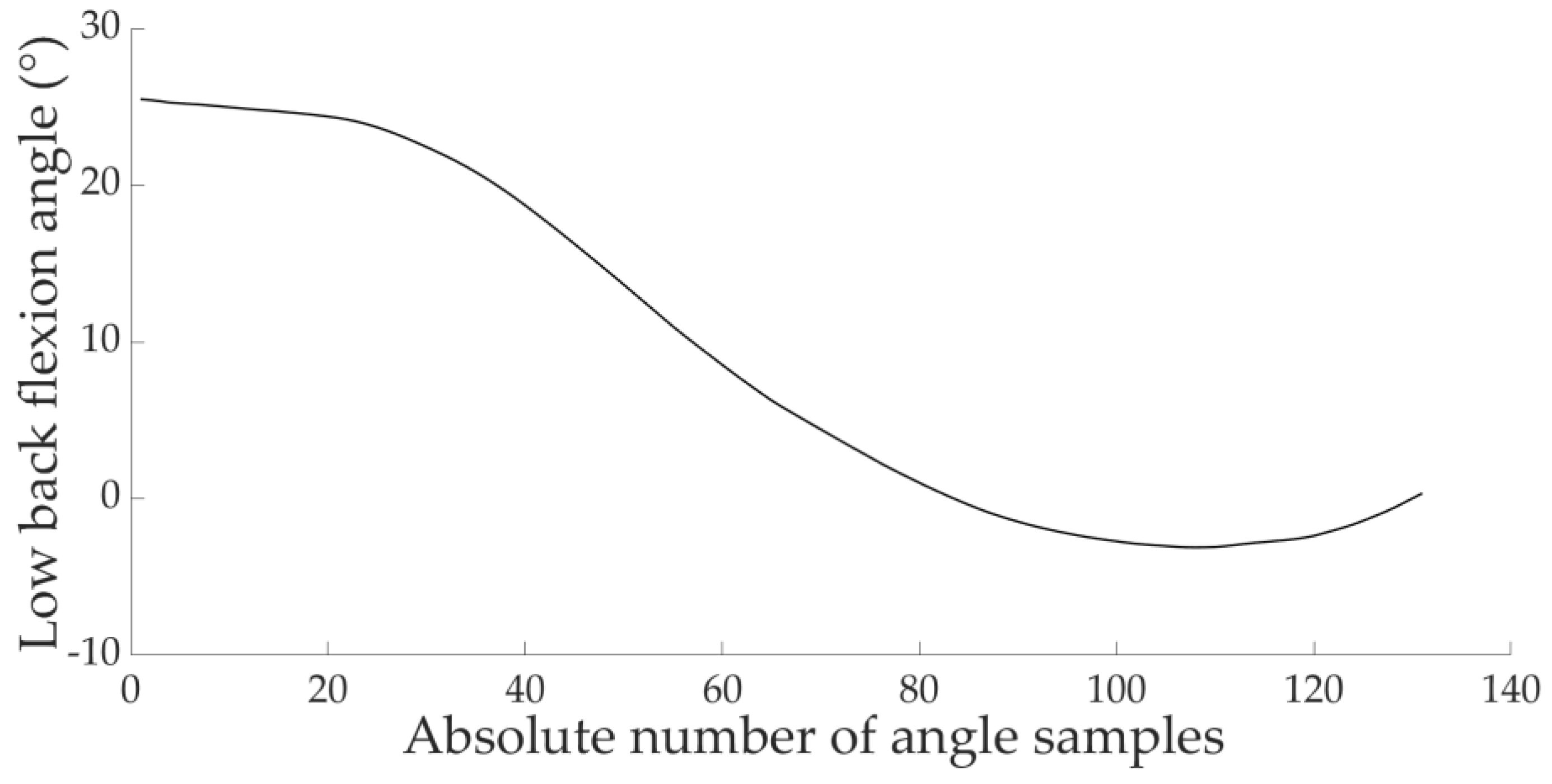
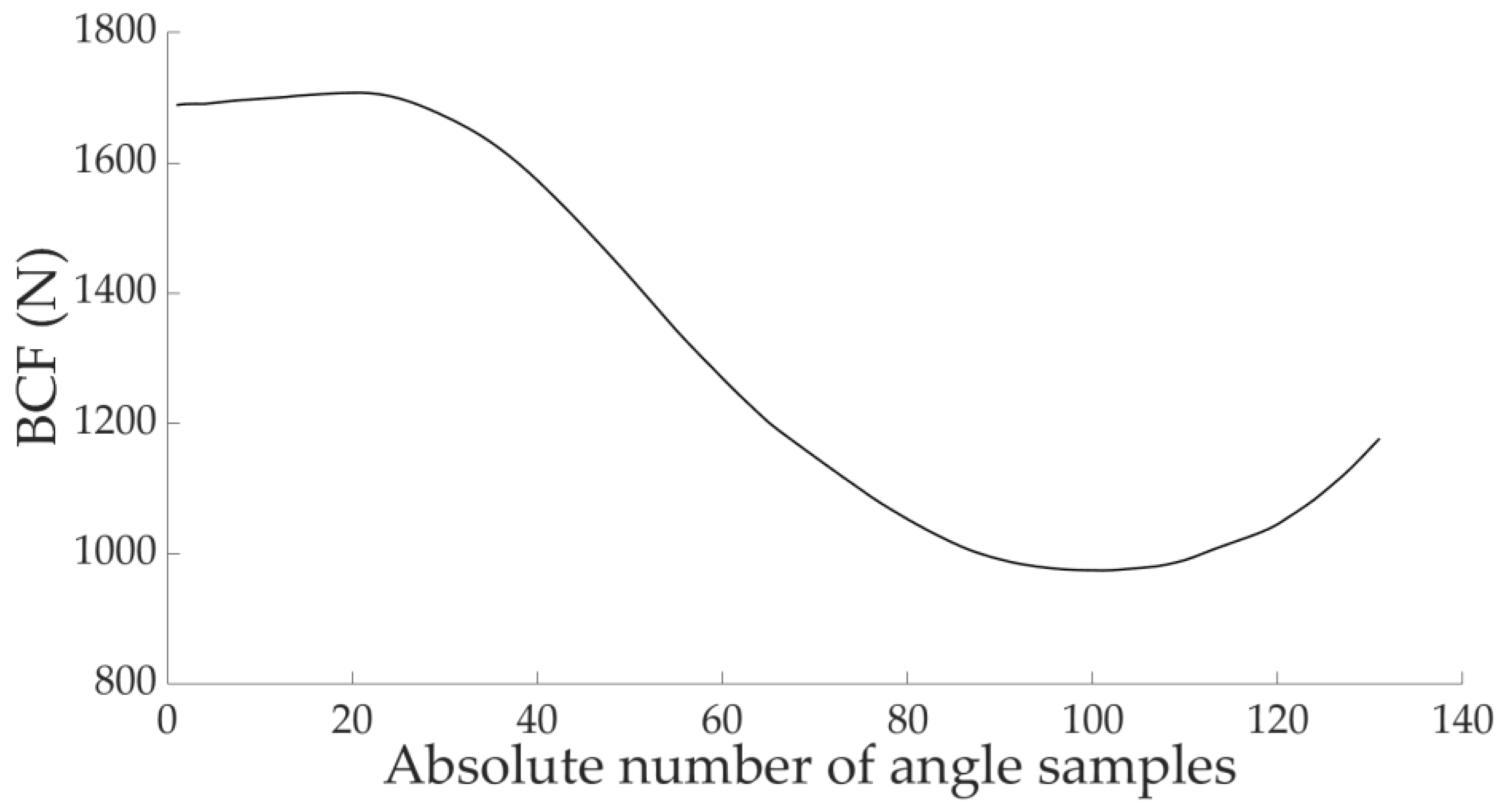
The major limitation of the current HCBCF model is that it is static. This research takes the first step in attempting to create a dynamic and practical injury risk factor estimation tool, by first validating a single inertial sensor method. Using the semi-automated approach presented for each point in time may be a simple means to monitor BCF dynamically for future research. However, linear interpolation (or other methods of converting static measures into dynamic) of manually measured variables is needed for this purpose (Figure 1). Flexion at L5-S1 may be monitored with a sensor for each point in time (Figure 2) and used with remaining linearly interpolated variables (Figure 1) to estimate dynamic BCF (Figure 3). This is one example of how semi-automation may be implemented to practically monitor BCF dynamically in the future, and is displayed to conceptualise this idea. The number of angle samples (X-axis) relates to each instance in time during a repetition and magnitude is on the Y-axis. Horizontal distance must still be measured manually at the origin and destination for each task to use this method. It is assumed that distance parameters may similarly vary (compared to flexion and BCF) during each repetition of a lifting task (Figure 1, Figure 2 and Figure 3). However, until more accurate (whilst remaining practical) methods are designed and validated, this linear interpolation method for the horizontal distance variable may be a simple means to semi-automate dynamic monitoring of BCF in the future.

4. Conclusions

Validation is the first step in applying new methodologies, and inertial sensors were shown to semi-automate BCF monitoring in a laboratory environment. This highlights the potential for a new series of research designs aimed at improving methodologies for practicality or using sensors for wide-scale lifting interventions.

Acknowledgments

Funded through the PhD research budget, provided by Charles Darwin University. This work was supported by Charles Darwin University and the National Institute of Fitness and Sports in Kanoya.

Conflicts of Interest

The authors declare no conflict of interest. The funding sponsors had no role in the design of the study; in the collection, analyses, or interpretation of data; in the writing of the manuscript, and in the decision to publish the results.

References

  1. Hoy, D.; March, L.; Brooks, P.; Blyth, F.; Woolf, A.; Bain, C.; Williams, G.; Smith, E.; Vos, T.; Barendregt, J.; et al. The global burden of low back pain: Estimates from the Global Burden of Disease 2010 study. Ann. Rheum. Dis. 2014, 73, 968–974. [Google Scholar] [CrossRef] [PubMed]
  2. Australian Bureau of Statistics. Work-Related Injuries JUL 2013 to JUN 2014; Australian Bureau of Statistics: Canberra, Australia, 2015. [Google Scholar]
  3. Adams, M.A. Biomechanics of back pain. Acupunct. Med. 2004, 22, 178–188. [Google Scholar] [CrossRef] [PubMed]
  4. Hoogendoorn, W.E.; Paulien, M.B.; Henrica, C.W.; Marjolein, D.; Bart, W.K.; Mathilde, C.M.; Geertje, A.M.A.; Bouter, L.M. Flexion and rotation of the trunk and lifting at work are risk factors for low back pain: Results of a prospective cohort study. Spine 2000, 25, 3087–3092. [Google Scholar] [CrossRef] [PubMed]
  5. McGill, S.M. Low Back Disorders, 3rd ed.; Human Kinetics: Champaign, IL, USA, 2015. [Google Scholar]
  6. Luinge, H.J.; Veltink, P.H. Measuring orientation of human body segments using miniature gyroscopes and accelerometers. Med. Biol. Eng. Comput. 2005, 43, 273–282. [Google Scholar] [CrossRef] [PubMed]
  7. Merryweather, A.S.; Loertscher, M.C.; Bloswick, D.S. A revised back compressive force estimation model for ergonomic evaluation of lifting tasks. Work 2009, 34, 263–272. [Google Scholar] [CrossRef] [PubMed]
  8. El-Gohary, M.A. Joint Angle Tracking with Inertial Sensors; Portland State University: Portland, OR, USA, 2013. [Google Scholar]
  9. Gleadhill, S.; Lee, J.B.; James, D. The development and validation of using inertial sensors to monitor postural change in resistance exercise. J. Biomech. 2016, 49, 1259–1263. [Google Scholar] [CrossRef] [PubMed]
  10. Bonnechere, B.; Jansen, B.; Salvia, P.; Bouzahouene, H.; Sholukha, V.; Cornelis, J.; Rooze, M.; Van Sint Jan, S. Determination of the precision and accuracy of morphological measurements using the Kinect™ sensor: Comparison with standard stereophotogrammetry. Ergonomics 2014, 57, 622–631. [Google Scholar] [CrossRef] [PubMed]
  11. Spector, J.T.; Lieblich, M.; Bao, S.; McQuade, K.; Hughes, M. Automation of Workplace Lifting Hazard Assessment for Musculoskeletal Injury Prevention. Ann. Occup. Environ. Med. 2014, 26, 1–8. [Google Scholar] [CrossRef] [PubMed]
  12. Waters, T.R.; Putz-Anderson, V.; Garg, A. Applications Manual for the Revised NIOSH Lifting Equation; US Dept. of Health and Human Services, Public Health Service, Centers for Disease Control, National Institute for Occupational Safety and Health: Cincinnati, OH, USA, 1994. [Google Scholar]
  13. Leadbetter, R.; James, D. Platform technologies and Visual analytics for inertial sensors. J. Fit. Res. 2016, 5, 16–18. [Google Scholar]
  14. Wada, T.; Mizutani, M.; Lee, J.; Rowlands, D.; James, D. 3D Visualisation of Wearable Inertial/Magnetic Sensors. Proceedings 2018, 2, 292. [Google Scholar]
  15. Lai, A.; James, D.A.; Hayes, J.P.; Harvey, E.C. Semi-automatic calibration technique using six inertial frames of reference, Microelectronics: Design, Technology, and Packaging. Int. Soc. Opt. Photonics 2004, 5274, 531–543. [Google Scholar]
  16. Madgwick, S.O.; Harrison, A.J.; Vaidyanathan, R. Estimation of IMU and MARG orientation using a gradient descent algorithm. In Proceedings of the 2011 IEEE International Conference on Rehabilitation Robotics Proceedings, Zurich, Switzerland, 1 July 2011; pp. 1–7. [Google Scholar]
  17. Hopkins, W.G. Spreadsheets for Analysis of Validity and Reliability. Sportscience 2015, 21, 36–44. [Google Scholar]
  18. Gleadhill, S.; James, D.; Lee, J. Validating Temporal Motion Kinematics from Clothing Attached Inertial Sensors. Proceedings 2018, 2, 304. [Google Scholar]
  19. Hopkins, W.; Marshall, S.; Batterham, A.; Hanin, J. Progressive statistics for studies in sports medicine and exercise science. Med. Sci. Sports Exerc. 2009, 41, 3. [Google Scholar] [CrossRef] [PubMed]
  20. Mohsin, F.; McGarry, A.; Bowers, R.J. Factors Influencing the Reliability of the Universal Goniometer in Measurement of Lower-Limb Range of Motion: A Literature Review. J. Prosthet. Orthot. 2015, 27, 140–148. [Google Scholar] [CrossRef]
  21. Camomilla, V.; Bergamini, E.; Fantozzi, S.; Vannozzi, G. Trends Supporting the In-Field Use of Wearable Inertial Sensors for Sport Performance Evaluation: A Systematic Review. Sensors 2018, 18, 873. [Google Scholar] [CrossRef] [PubMed]
  22. Papi, E.; Koh, W.S.; McGregor, A.H. Wearable technology for spine movement assessment: A systematic review. J. Biomech. 2017, 64, 186–197. [Google Scholar] [CrossRef]
Figure 1. Linear interpolation of horizontal distance (group mean) between origin and destination.
Proceedings 49 00037 g001
Figure 2. Absolute L5-S1 flexion angle (group mean) from the sensor method between origin and destination.
Proceedings 49 00037 g002
Figure 3. BCF (group mean) from inertial sensor semi-automation method between origin and destination.
Proceedings 49 00037 g003
Table 1. Typical error of the estimate.
OutputPracticalStandardised ErrorRaw ErrorPearson CorrelationMean Bias in Raw Units
Angle (°)Inertial sensor0.90, large
(95% CL 0.76–1.10)
5.90°
(95% CL 5.39–6.53)
r = 0.74
(95% CL 0.67–0.80)
−2.29°
(95% CL −3.09–−1.48)
Angle (°)Hand calculated2.51, extremely large
(95% CL 1.82–3.92)
8.18°
(95% CL 7.46–9.04)
r = 0.37
(95% CL 0.25–0.48)
13.38°
(95% CL 11.24–15.51)
BCF (N)Inertial sensor0.52, moderate
(95% CL 0.45–0.61)
191.61 N
(95% CL 174.83–211.97)
r = 0.89
(95% CL 0.85–0.91)
−73.34 N
(95% CL −100.03–−46.64)
BCF (N)Hand calculated1.68, very large
(95% CL 1.31–2.26)
355.73 N
(95% CL 324.59–393.55)
r = 0.51
(95% CL 0.40–0.61)
399.99 N
(95% CL 335.21–464.77)
Legend: ° = Representing absolute torso flexion angle at L5-S1; BCF = Back compressive force; CL = Confidence limits; N = Newtons; r = Pearson correlation coefficient.
Publisher’s Note: MDPI stays neutral with regard to jurisdictional claims in published maps and institutional affiliations.