Proceeding Paper

Pointing Error Evaluation of the High Spatial Resolution Imaging Camera of BepiColombo Space Mission †

by
Daniele Dipasquale
1,*,
Stefano Debei
2,3,
Gabriele Cremonese
4,
Fabrizio Capaccioni
5 and
Pasquale Palumbo
6
1
Department of Aeronautical Engineering, International Academy of Aviation Industry, King Mongkut’s Institute of Technology Ladkrabang, Bangkok 10520, Thailand
2
Centre of Studies and Activities for Space (CISAS)—“G.Colombo”, University of Padua, Via Venezia 15, 35131 Padova, Italy
3
Department of Industrial Engineering, University of Padua, Via Venezia 1, 35131 Padova, Italy
4
INAF, Osservatorio Astronomico di Padova, Vicolo dell’Osservatorio 3, I-35122 Padova, Italy
5
INAF, Istituto di Astrofisica e Planetologia Spaziale, Via del Fosso del Cavaliere 100, 00133 Rome, Italy
6
Dipartimento Scienze e Tecnologie, Universitá Parthenope, Centro Direzionale, Isola C4, 80143 Napoli, Italy
*
Author to whom correspondence should be addressed.
Presented at the Innovation Aviation & Aerospace Industry—International Conference 2020 (IAAI 2020), Chumphon, Thailand, 13–17 January 2020.
Proceedings 2019, 39(1), 20; https://doi.org/10.3390/proceedings2019039020
Published: 8 January 2020

Abstract

:
Thermo-elastic analyses of the High spatial Resolution Imaging Camera (HRIC), which is part of the spectrometers and imagers for the Mercury Planetary Orbiter BepiColombo Integrated Observatory SYStem suit (SIMBIO-SYS), are carried out to evaluate the effect of thermo-elastic deformation on the pointing error of the camera.

1. Introduction

BepiColombo is a planned European-Japanese space mission to Mercury [1] which was successfully launched on 19 October 2018. The mission includes the orbiter Mercury Planet Orbiter (MPO) developed under ESA’s supervision (European Space Agency) which is carrying the suite SIMBIO-SYS [2] (Spectrometers and Imagers for MPO BepiColombo Integrated Observatory SYSstem) to whom all the imaging operations and part of the spectroscopic observations are assigned. The suite consists of three optical instruments operating on different channels mounted on a common optical bench, in particular, the optical instrument named HRIC [3,4] (High spatial Resolution Imaging Camera) will provide high-resolution images of planetary surface targets such as craters, lava flows, tectonic structures, etc., which are strategic for the study of the interaction among geological, geophysical and geochemical processes as well as the effects of impact processes. HRIC will operate in a space environment characterized by severe thermal loads, therefore, it is clear that the thermal stability of the camera will play a fundamental role in achieving the mission requirements. In this work, we carry out thermal-mechanical analyses. As the first step, we develop a thermal model for predicting the range of temperatures that the camera will endure in orbit, then we develop a mechanical model for the evaluation of the thermal distortions. Finally, the optical performance is evaluated in terms of pointing error.

2. HRIC Instrument

HRIC telescope was accurately designed in order to satisfy the requirement of high-resolution images over the covered field of view of 1.47°, with a panchromatic filter and 3 broadband filters in the spectral range 400–900 nm. The optical design is based on a catadioptric concept, where the layout consists of an optimized Ritchey—Chrétien configuration with a dedicated corrector of 3 refractive elements. The two mirrors are characterized by a hyperboloid profile that, together with the corrector lenses, leads to having a focal length of 800 mm, while the pupil aperture located on the primary mirror has a diameter of about 90 mm. A 2048 × 2048 pixels SiPIN Complementary Metal Oxide Semiconductor (CMOS) sensor with a pixel size of 10 µm is used for capturing the images. In Figure 1 the section drawing of the camera is displayed so that the layout and the main components of the telescope can be distinctly seen. The camera is nadir pointing and will operate in a polar orbit with a Periherm altitude of 480 km and an Apoherm altitude of 1500 km.

3. HRIC Model

In the following we introduce the thermal and mechanical models implemented for evaluating the thermo-elastic distortions, all models have been obtained by mainly extracting the middle surfaces from the CAD (Computer-Aided Design) camera model, except for the two mirrors which are represented by the reflective surfaces. At this stage of preliminary analyses, the corrector lenses are not modeled.

3.1. Thermal Model

The camera is discretized with lumped-based 2D elements by means of the commercial software ESATAN-TMS [5,6]. The geometrical model is displayed in Figure 2 with the associated list of bulk materials.
The thermal properties of the bulk materials are given in Table 1, while in Table 2 the thermal-optical properties of the coatings are given. The transient analysis is performed for the hottest case of the thermal space environment, which is at the Perihelion position of Mercury where the illuminated surface reaches a temperature of 688 K and the dark side 100 K. An albedo coefficient of 0.12 is assumed. The S/C internal environment, which contains the camera, is kept at the boundary temperature of 50 °C, while the baffle which is conductively decoupled from the camera is conductively linked to a node which is set at a boundary temperature of 65 °C [7]. The node represents the thermal interface of the S/C bracket for the mounting of the baffle. The electrical heat dissipation coming from the Proximity Electronics and the Detector (see Figure 1) are neglected since cold fingers provided by S/C are adopted for removing the heat. Moreover, the heat flux between the S/C optical bench where HRIC is fixed and the camera can be neglected.

3.2. Mechanical Model

The camera is discretized with 2D linear shell elements, with a total of 521,797 nodes and 88,579 elements by using the commercial FEM (Finite Element Method) software Patran/MSC Nastran. The model is implemented without the baffle, being this one mechanically decoupled from the camera. Table 3 gives the mechanical properties of the used materials. Static analyses are carried out by imposing as boundary condition the temperature at each node of the mechanical mesh, in this regard, in-house MATLAB codes have been written for interpolating the boundary temperature field given the temperature field computed in ESATAN-TMS. Moreover, fixed constraints are applied to the 4 holes at the bottom of the composite box.

4. Results

Several orbital positions are simulated in order to capture the highest temperature reached on the camera, in Figure 2a the contour plot of the temperature for such a case is displayed. The highest temperature of 87.3 °C is reached on the external baffle ring while approximately the average temperature in the camera is kept constant at about 58 °C with thermal gradients throughout the camera of few degrees. This result was foreseeable in consequence of an accurate thermal design of the camera, especially the Stravroudis baffle configuration for rejecting toward the sky-background the incoming radiation misaligned with respect to the optical axis and the TIRD filter [8] for cutting the infrared radiation coming mainly from the planet. Figure 2b shows the deformed camera with the contour plot of the displacements due to the thermo-elastic deformations, with a maximum displacement of 37.4 µm for M1 and 37.9 µm for M2.
Figure 2. (a) Contour plot of the temperature computed at the hottest orbital position, (b) deformed telescope with the contour plot of the displacements.
Proceedings 39 00020 g003
The effect of piston/tilt of the two mirrors on the pointing error of the camera is evaluated by decomposing their deformation with the use of Zernike polynomials, see [8] for more details about the optical prescriptions of HRIC layout. The PSF (Point Spread Function) displayed in Figure 3 shows how the peak of luminous intensity is located at a distance of about 3.24 µm from the center (the ideal condition of optical alignment is at 20 °C), which is enclosed within the central pixel of the optical sensor (the pixel has the size of 10 µm). It can, therefore, be concluded that the pointing error can be neglected in the Perihelion MPO orbit.
Figure 3. PSF on-axis, the square patch has a size of 99.2 µm which is about an area of 10 × 10 pixel of the detector (the scale of the color-map is linear and normalized to peak of PSF).
Proceedings 39 00020 g004

5. Conclusions

Thermo-mechanical analyses of HRIC telescope are carried out in order to evaluate the effects of thermal-elastic deformations on the pointing error of the camera. In particular, we aim to evaluate it when HRIC is operating in the worst thermal environmental condition, which is at Perihelion orbit. The results show how the piston/tilt movement of the primary and secondary mirror introduces a slight deviation of the peak luminous intensity from the center of the sensor, however, the pointing error can be neglected since the peak luminous intensity lies within the central pixel of the sensor.

Acknowledgments

We gratefully acknowledge funding from the Italian Space Agency (ASI) under ASI-INAF agreement 2017-47-H.0. We also thank Leonardo S.P.A for their role as prime industrial partner in the design, manufacturing and testing of the HRIC instrument.

References

  1. Benkhoff, J.; Van Casteren, J.; Hayakawa, H.; Fujimoto, M.; Laakso, H.; Novara, M.; Ferri, P.; Middleton, H.R.; Ziethe, R. BepiColombo—Comprehensive exploration of Mercury: Mission ovserview and science goals. Planet. Space Sci. 2010, 58, 2–20. [Google Scholar] [CrossRef]
  2. Flamini, E.; Capaccioni, F.; Colangeli, L.; Cremonese, G.; Doressoundiram, A.; Josset, J.L.; Langevin, Y.; Debei, S.; Capria, M.T.; De Sanctis, M.C.; et al. SIMBIO-SYS: The spectrometer and imagers integrated observatory system for the BepiColombo planetary orbiter. Planet. Space Sci. 2010, 58, 125–143. [Google Scholar] [CrossRef]
  3. Marra, G.; Colangeli, L.; Mazzotta Epifani, E.; Palumbo, P.; Zusi, M.; Debei, S.; Flamini, E.; Cosi, M. The optical design of the high resolution imaging channel for the SIMBIO-SYS experiment on the BepiColombo mission to Mercury. Mem. Soc. Astron. Ital. 2008, 12, 77–82. [Google Scholar]
  4. Zusi, M.; Palumbo, P.; Colangeli, L.; Marra, G.; Epifani, E.M.; Della Corte, V.; Molfese, C.; Flamini, E. Observing Mercury with the high resolution imaging channel of SIMBIO-SYS. In Proceedings of the European Planetary Science Congress (EPSC), Rome, Italy, 19–24 September 2010; p. 695. [Google Scholar]
  5. ESATAN-TMS Thermal Engineering Manual; ITP Engines: Leicester, UK, 2019.
  6. ESATAN-TMS Workbench User Manual; ITP Engines: Leicester, UK, 2009.
  7. Friso, E. Thermal Effects Reduction Techniques for the SIMBIO-SYS Scientific Suite of BEpiColombo Mission. Ph.D. Thesis, Centre of Studies and Activities for Space “G.Colombo”, University of Padova, Padova, Italy, 2010. [Google Scholar]
  8. Zusi, M.; Paolinetti, R.; Della Corte, V.; Marra, G.; Baroni, M.; Palumbo, P.; Cremonese, G. Optical Design of the High Resolution Imaging Channel of SIMBIO-SYS. Appl. Opt. 2019, 58, 4059–4069. [Google Scholar] [CrossRef] [PubMed]
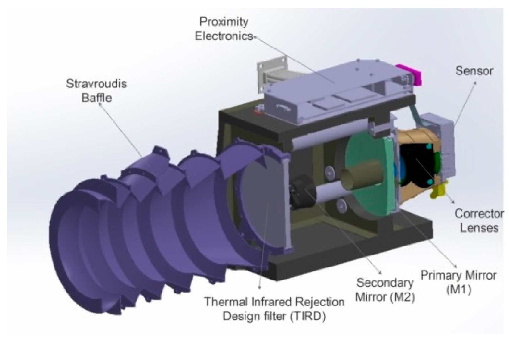
Figure 1. Main components of the HRIC telescope.
Proceedings 39 00020 g001
Figure 2. Geometrical model with the list of bulk materials adopted in the commercial software ESATAN-TMS.
Proceedings 39 00020 g002
Table 1. Thermal properties of the bulk materials used in the thermal model.
MaterialDensity [kg/m3]Specific Heat [J/kg∙K]Conductivity [W/m∙K]
Titanium 6Al4V4430526.36.7
INVAR805051510.15
Honeycomb composite panel1558725.822.4/23.6/1.46 1
Glass BK7G1825208201.19
Glass Fused Silica HOQ31022007721.42
Aluminum Alloy RSA60612800850130
1 Out-of-plane thermal conductivity.
Table 2. Thermal-optical properties of the coatings.
Coatingϵ τ I R ρ I R d ρ I R s α τ s ρ s d ρ s s
RSA6061 aeroglaze (internal baffle front ring)0.8500.0750.0750.9600.020.02
RSA6061 polished (internal baffle)0.0500.050.90.1200.030.85
RSA6061 Alodine (external baffle)0.1500.4250.4250.3500.3250.325
Coating Mirrors0.02000.980.1000.9
TIRD glass (inward)0.9600.0400100
TIRD glass (outward)0.2500.7500.20.800
INVAR0.3100.6900010
Composite panel0.7000.3000010
MLI cover0.0500.9500.1500.850
S/C internal environment (black body)10001000
Table 3. Mechanical properties of the materials adopted in the mechanical model.
MaterialYoung’s Module [GPa]Poisson’s CoefficientThermal Expansion Coefficient [10-6/K]
Titanium 6Al4V113.80.3428.6
INVAR1480.281.3
Honeycomb composite panel19.9/22.40.29.52/11.6
Glass BK7G18820.2057
Glass Fused Silica HOQ310700.170.51