Experimental Investigation of the Ground Effect of WIG Craft—NEW1 Model †

Abstract
:1. Introduction
2. Experimental Method
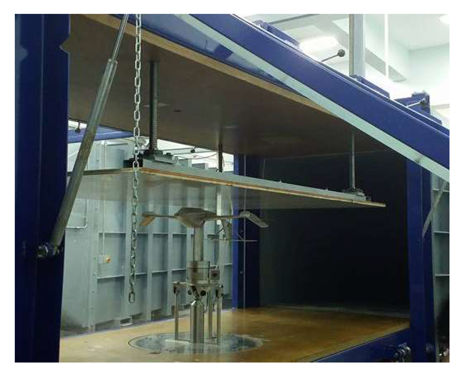
2.1. Wind Tunnel
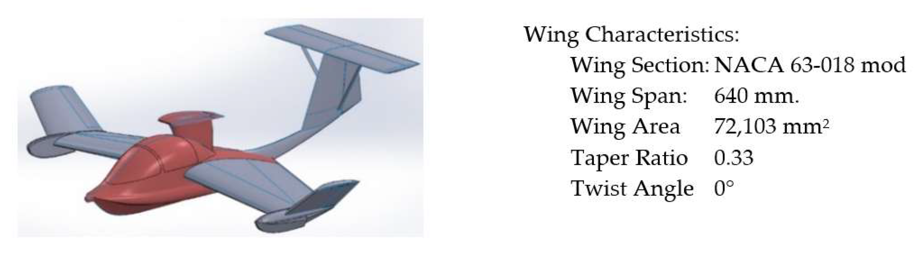
2.2. Model
2.3. Ground Surface Model
2.4. Force Balance and Measurement
3. Results and Discussions
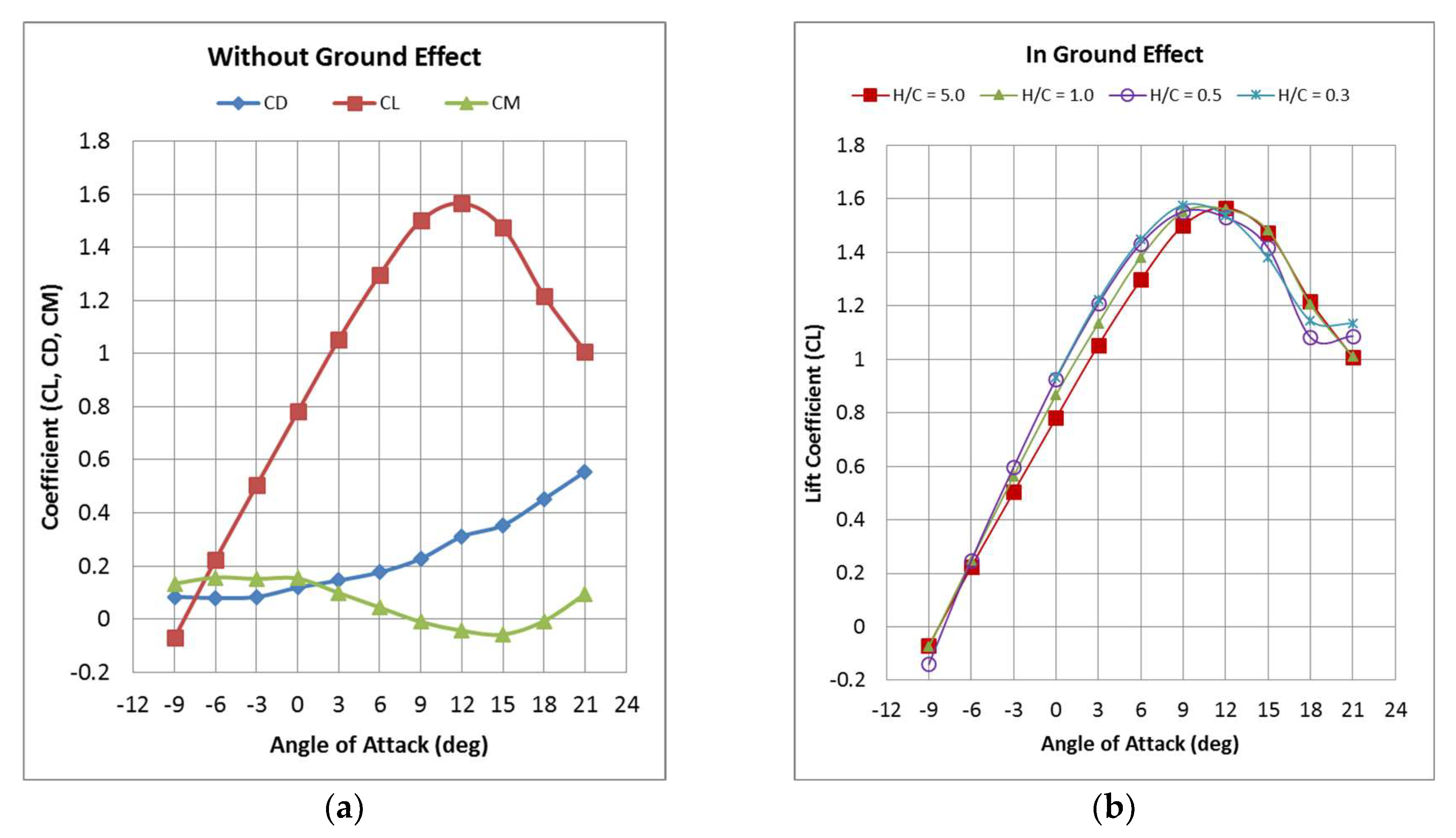
3.1. Without Ground Effect
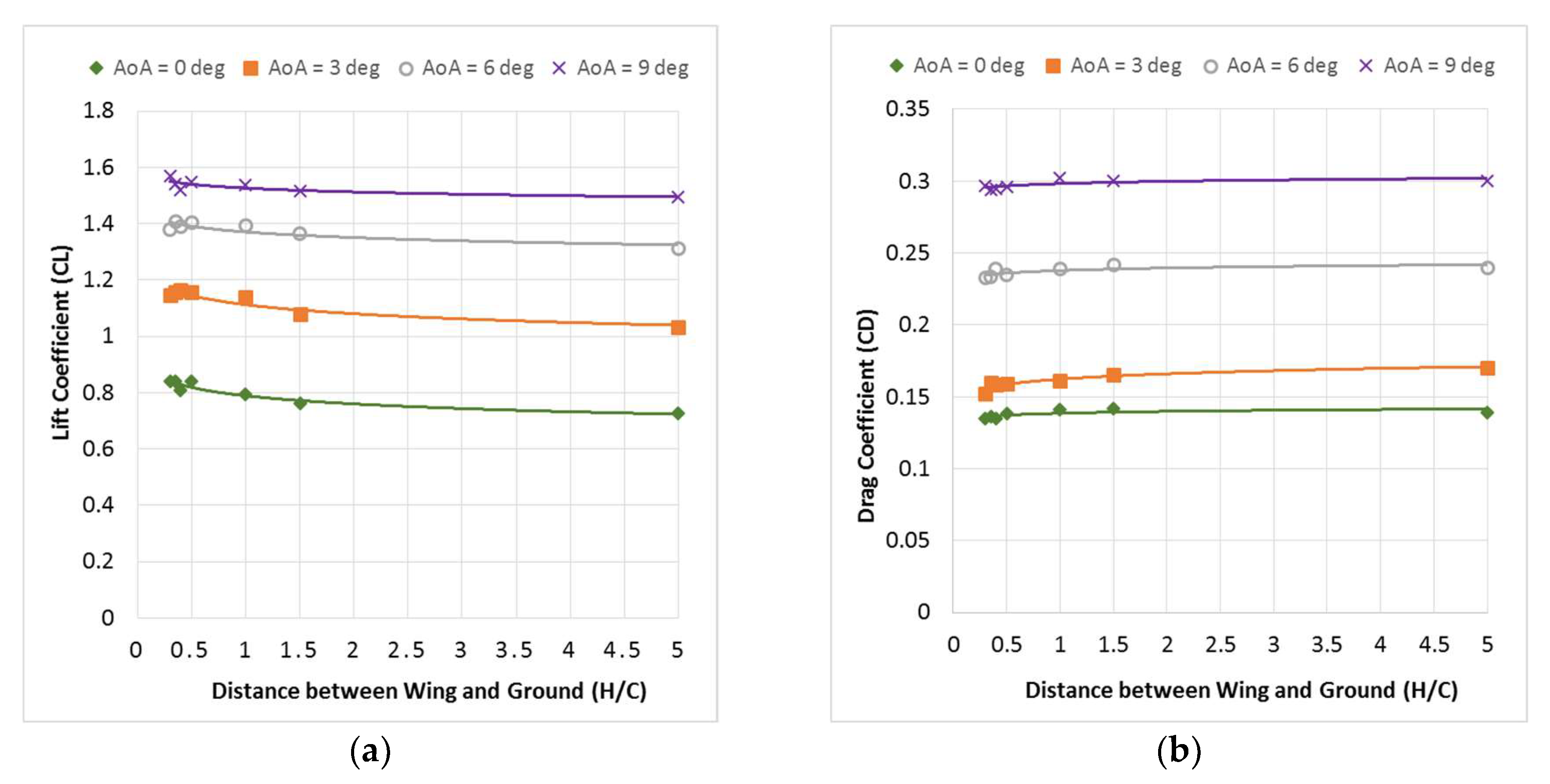
3.2. CL and CD of the WIG Craft in Ground Effect
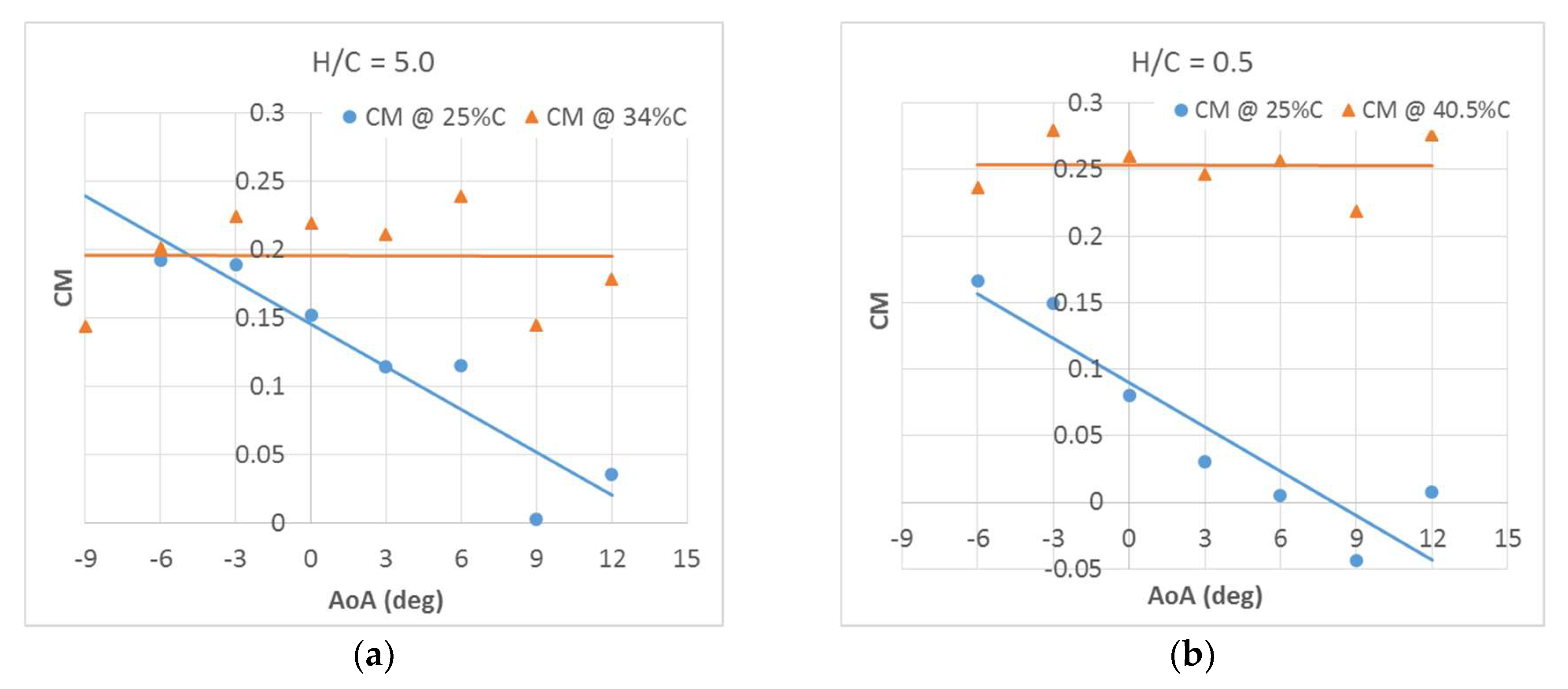
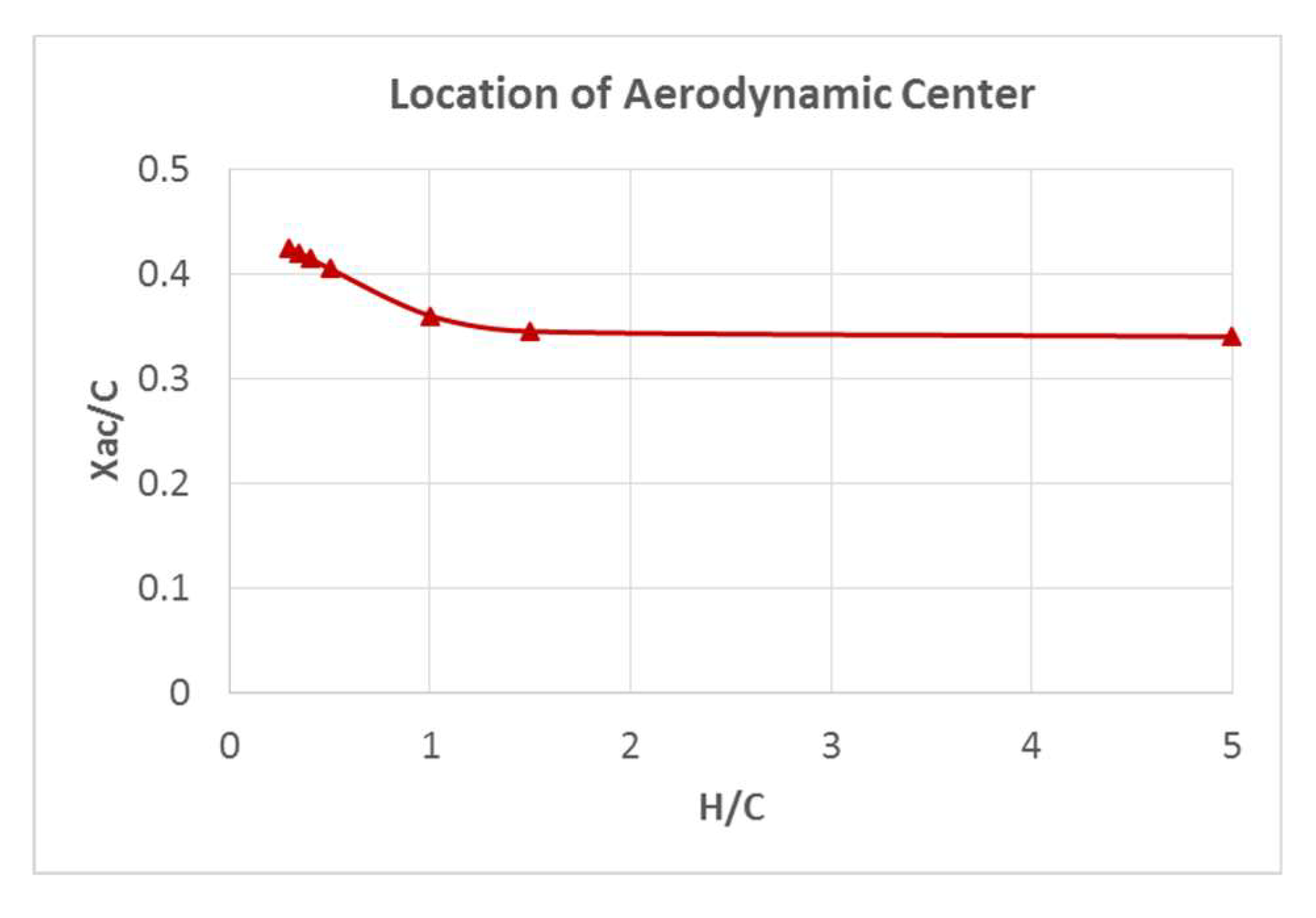
3.3. CM and AC Location of the WIG Craft in Ground Effect
4. Conclusions
Funding
References
- Moore, N.; Wilson, P.A.; Peters, A.J. An Investigation into Wing in Ground Effect Airfoil Geometry. In RTO-MP-095; NATO RTO.11; NATO RTO: Washington, DC, USA, 2002; pp. 1–27. [Google Scholar]
- Tofa, M.M.; Maimun, A.; Ahmed, Y.M.; Jamei, S.; Priyanto, A. Experimental Inestigation of a Wing-in-Ground Effect Craft. Sci. World J. 2014, 2014, 489308. [Google Scholar] [CrossRef] [PubMed]
- Rattapol, S.; Siripong, A. Experimental Investigation of Seabird-like Wings in Ground Effect. J. Aeronaut. Astronaut. Aviat. 2019, 51, 213–224. [Google Scholar]
- Cui, E.J. Advance and problems in WIG vehicle research and application. In Proceedings of the High Performance Marine Vehicles Conference, Shanghai, China, August 2003; Volume 1, pp. 1–6. [Google Scholar]
- Rozhdestvensky, K.V. Wing-in-ground effect vehicles. Prog. Aerosp. Sci. 2006, 42, 211–283. [Google Scholar] [CrossRef]
- Yang, W.; Yang, Z.; Ying, C. Effects of design parameters on longitudinal static stability for WIG craft. Int. J. Aerodyn. 2010, 1, 97–113. [Google Scholar] [CrossRef]
- Rattapol, S.; Chinnapat, T.; Siripong, A. Aerodynamic Test of the WIG Craft Model (New One) in the WIND TUNnel; Research Report; Kasetsart University: Bangkok, Thailand, 2019. [Google Scholar]

| Parameter | Variable | Value |
|---|---|---|
| Wing to Ground Distance Ratio | H/C | 0.3, 0.4, 0.5, 1.0, 1.5 and 5.0 |
| Angle of Attack | θ | −9 to 21 deg at a step of 3 deg. |
© 2020 by the authors. Licensee MDPI, Basel, Switzerland. This article is an open access article distributed under the terms and conditions of the Creative Commons Attribution (CC BY) license (http://creativecommons.org/licenses/by/4.0/).
Share and Cite
Sakornsin, R.; Thipyopas, C.; Atipan, S. Experimental Investigation of the Ground Effect of WIG Craft—NEW1 Model. Proceedings 2019, 39, 17. https://doi.org/10.3390/proceedings2019039017
Sakornsin R, Thipyopas C, Atipan S. Experimental Investigation of the Ground Effect of WIG Craft—NEW1 Model. Proceedings. 2019; 39(1):17. https://doi.org/10.3390/proceedings2019039017
Chicago/Turabian StyleSakornsin, Rattapol, Chinnapat Thipyopas, and Siripong Atipan. 2019. "Experimental Investigation of the Ground Effect of WIG Craft—NEW1 Model" Proceedings 39, no. 1: 17. https://doi.org/10.3390/proceedings2019039017
APA StyleSakornsin, R., Thipyopas, C., & Atipan, S. (2019). Experimental Investigation of the Ground Effect of WIG Craft—NEW1 Model. Proceedings, 39(1), 17. https://doi.org/10.3390/proceedings2019039017