1. Introduction
Designing buildings against accidental loading, terrorist attacks or effects from military munitions are relevant considering todays international threat assessments. In recent years, applying numerical tools for damage evaluation and for design of buildings against blast loading have become more prevalent. Full-scale validation by testing is expensive and not always feasible. Hence, reliable numerical models for local and global response calculations of structures are an attractive substitute. Multi-story buildings designed to withstand blast load are often constructed of monolithic concrete structures. Numerical models of multi-story buildings demand computational expensive element and material models. Several studies on the applicability of modelling entire buildings exposed to impulse loadings have been performed in recent years. Bermejo et al. [
1] conducted simulations of full-scale buildings exposed to blast load and compared the response of solid element and structural element formulations. A study by Y.A. Al-Salloum [
2] on progressive collapse of a building exposed to blast loading presents an advanced numerical analysis procedure to predict the progressive collapse of reinforced concrete buildings exposed to blast loading. A number of studies on predicting flexural response of concrete components exposed to blast load numerically, have also been performed the last decade, e.g., [
3,
4]. Castedo et al. [
5] investigated the advantage and accuracy of applying numerical simulations on concrete slabs validated with full-scale experiments.
However, literature involving experiments with global stability of reinforced concrete structures exposed to blast loading is limited. As a part of an EU-project where the scope was to calibrate a particular damage assessment software, a full-scale test where a three-story reinforced concrete building was exposed to exterior blast loading was conducted. The experiment has been used to evaluate the performance of FE simulations to represent global response of reinforced concrete structures exposed to blast loading presented in this work. The main objective is to verify the use of numerical simulations as a tool for damage evaluation of buildings and to investigate the prospects of applying numerical simulations as a design tool for reinforced concrete structures subjected to blast loading.
2. Experimental Setup
The experiment consisted of a monolithic three-story building casted on-site with footprint 5.0 × 12.0 m and height 7.5 m. The load bearing walls of reinforced concrete were 250 mm thick, the columns 250 × 250 mm and the slabs 120 mm thick, supported by 250 × 380 mm girders spanning across the building. The exterior walls consisted of 250 × 250 × 500 mm Leca blocks with no constraining to the concrete walls. Average compressive cube strength of the concrete was 35 MPa. The concrete walls were doubly reinforced with ø10 c/c 185 mm longitudinal bars and ø10 c/c 193 mm horizontal bars with ø8 shear stirrups along the boundaries. Reinforcement type was standard B500C. The structural response and pressure were recorded with eight accelerometers, eight pressure gauges and one 1.5 kHz laser displacement gauge as shown in
Figure 1. The explosive charge was a cylindrically casted 400 kg TNT charge centered 13 m from the front wall.
3. Numerical Study
Based on preliminary studies on relevant constitutive models for concrete in LS-DYNA, CSCM (159) developed by the US Federal Highway Administration [
6] was chosen to represent the concrete as it exhibited adequate representation of damage and flexural response, as accordingly seen in the literature, e.g., [
7,
8]. The response of the building is studied applying two different modeling approaches; a solid element model with explicit reinforcement and a structural element model of shell elements with implicit reinforcement. The concrete elements in the solid element model are of reduced integration hexahedrals with element size 31.25 mm. Reinforcement is represented by the Hughes-Liu beam elements, constrained with Constrained Lagrangian in Solid (CLIS) [
9]. The element size of the reinforcement bars is approximately twice the size of the solid elements to limit the computational costs. However, this is not an ideal discretization and may cause instabilities. The compressive strength of the concrete is set to 35 MPa and the yield strength of the reinforcement bars is set to 500 MPa. The Leca walls are represented by concrete elements with adjusted compressive cube strength and density. For simplicity reasons the building is modelled as clamped to the ground. The structural element model consists of Hughes-Liu shell elements with five integration points over the thickness. Shell element size is also set to 31.25 mm and the shell thickness is specified to 250 mm for the concrete walls, 125 mm for the slabs and 125 mm for the Leca walls. The material model applied to the concrete is 172-EC2 and the building is modeled as clamped to the ground. The shock propagation is studied with the CFD code Chinook [
10] and compared to the semi-empirical tool ConWep. Coupled simulations of the blast and response are shown not to be critical to the results. Hence, the ConWep based tool implemented in LS-DYNA, *LOAD_BLAST_ENHANCED [
9] is applied to define the blast load. The simulations are run for 200 ms.
4. Results and Discussion
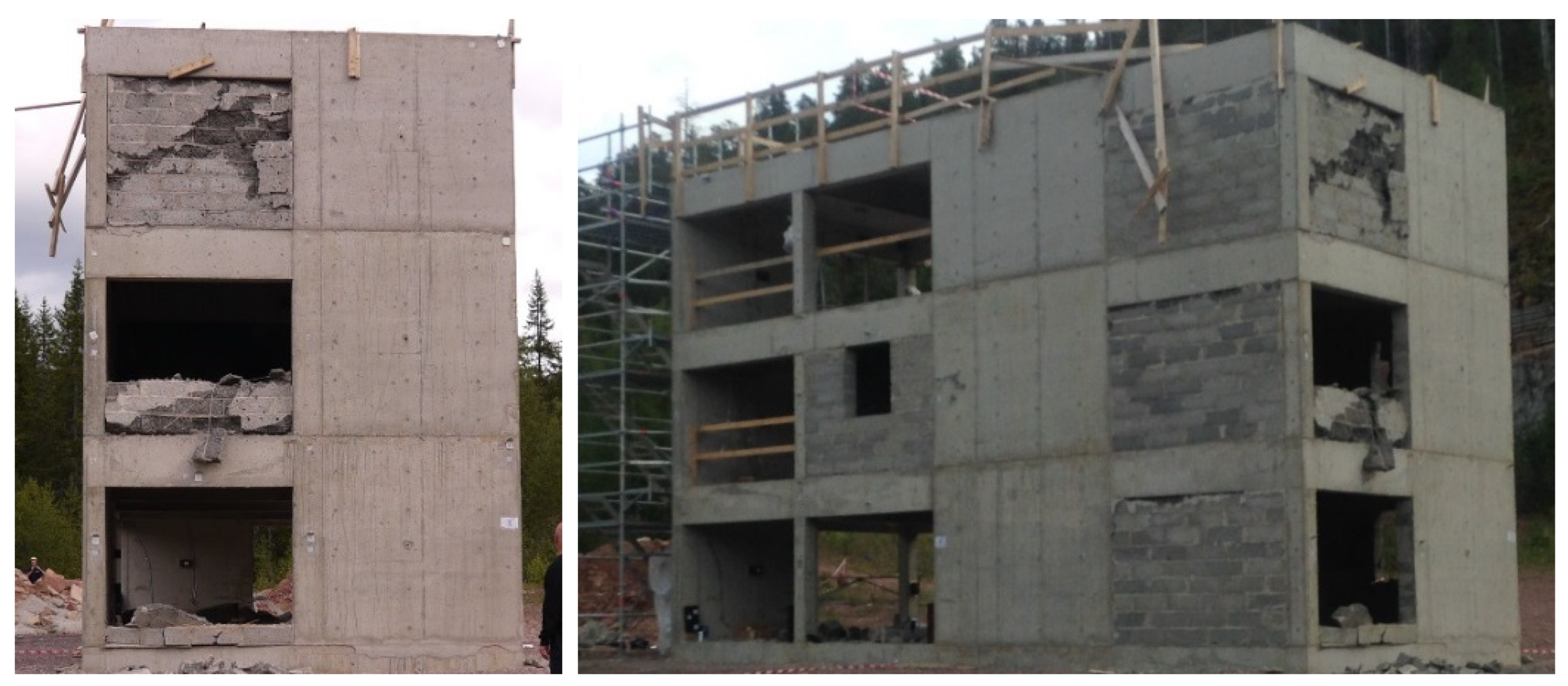
The global damage of the building after the air-blast is shown in
Figure 2. The concrete wall facing the charge experienced cracks across the span from the free edge to the center of the plate and then diagonally out to the fixed corners. Naturally, Level 1 experienced most damage, then decreasing with increasing height. It was not registered damage to other parts of the structural support system, i.e., shear walls, slabs, columns or girders in the building.
Comparison of the velocity and displacement history in longitudinal direction at gauge A7 located at the Level 3 are shown in
Figure 3. The velocity is slightly higher in the numerical simulations than observed in the experiment. The oscillations and drop in velocity after the peak are well captured. The permanent global displacement of the structure is not obtained as the accelerometer recordings drift after 50 ms. Assuming that the total mass is accurately represented, the solid element model behaves less rigid than the structure in the experiment.
Damage plot of the building from the numerical simulations is shown in
Figure 4 for the solid and structural element model, respectively. For the solid element model, red elements indicate failed elements due to either ductile or brittle damage. Small cracks occur in the concrete façade and there are also indications of cracks in the shear walls at Level 1. These cracks probably occur due to the clamped boundary conditions and could explain the less rigid solid element model. Visually there is good coincidence between the solid element model and the experiment. The fringe plot of the structural element model shows plastic strains in the reinforcement, where red areas indicate reinforcement with higher plastic strains than 1%. Plastic strains in the reinforcement occurs at the front wall, otherwise there is little damage of the structural element model.
The velocity and the displacement in horizontal direction at gauge A1 are compared for the experiment and the numerical simulations with solid and structural elements in
Figure 5 for the first 50 ms. The initial velocity of the front wall and the following oscillations are sufficiently captured in the numerical simulations. The peak and permanent displacement are also adequately represented. The structural element model displays more rigid behavior of the flexural response of the front wall than the solid element model, as accordingly for the global response. The permanent displacement of the front wall at Level 1 is approximately 11 mm and 5 mm for the solid element model and the structural element model, respectively, while the permanent displacement of the front wall in the experiment was approximately 7 mm (not shown in figure).
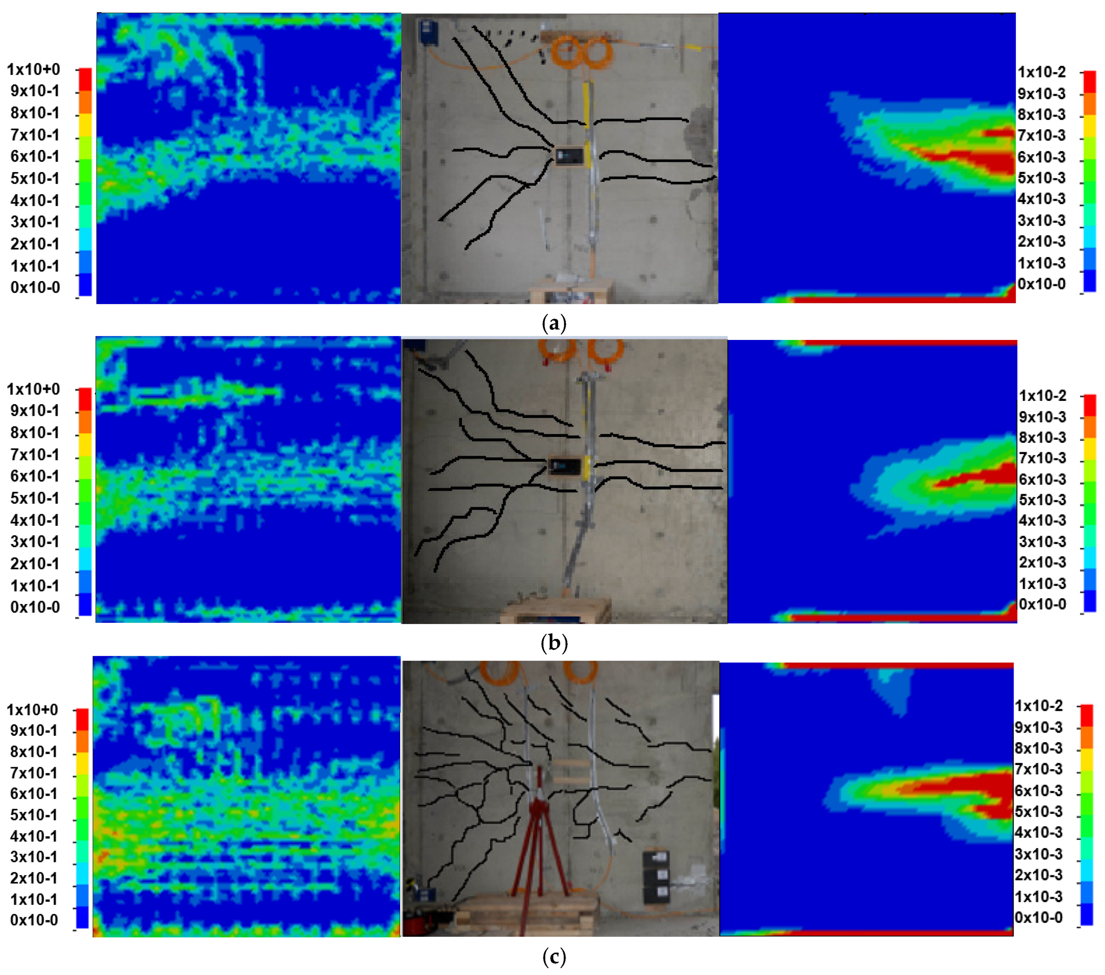
The local damage of the rear of the front wall is shown in
Figure 6 for Level 3 (a), Level 2 (b) and Level 1 (c) of the building. The crack pattern on the front wall observed in the experiment is similar to the results in the solid element model. In the structural element model plastic strains occur at locations where the reinforcement is expected to be highly utilized.
A mesh sensitivity study shows that the solid element model is quite dependent on the element size and the computational cost increase rapidly as the mesh is refined. The element size of the beam elements in the solid model also proves to have great influence on the accuracy. The structural element model is found to be less sensitive to mesh size. Notably, the use of structural elements provide a significant reduction in computational costs with limited loss in accuracy of the global response compared to the solid element model. A brief study on the global response of the building applying the different constitutive models from the preliminary studies has also been conducted. The different models provides as expected quite similar results since the global response is close to elastic. However, the run time for the different constitutive models range from eight hours (72R3-K&C) to 15 hours (272-RHT) for element size 31.25 mm, which may have great impact on the designated material model for large numerical models.
5. Concluding Remarks
For evaluating global response of multi-story buildings, both the solid element model and the structural element model represent the global displacement of the building within reasonable limits. For cases with local response of structural components, e.g., columns or facades, a solid element model is necessary to achieve adequate results. However, the structural element model proves to be a quick and easy tool for global damage assessment of reinforced concrete buildings.
Material model CSCM seem to be able to represent both local and global damage in the same model, reproducing cracks and displacements according to the experiment. Further work on global response of reinforced concrete structures should include a study of different material models’ abilities to represent global deformations of multi-story buildings in plastic domain. Global response of reinforced concrete structures exposed to blast loading may require different calibration of the material models to provide adequate results or to keep computational costs at a restrained level, compared to material models applied for close-range charges with high confined pressures.
The results in this work show that applying numerical tools for design are highly relevant and feasible at an affordable computational cost, but further validation of the numerical models is still necessary for design purposes.
Author Contributions
The work in this study is performed by S.H. at NDEA with contributions from K.B., P.I. and S.O.C.
Acknowledgments
The experiment was conducted in cooperation with the EU-project Reconass. The authors gratefully acknowledge the work of Håkan Hansson (FOI), Roger Berglund (FOI) and Tobias Carlberg (FOI), and the Reconass project team lead by project manager Evangelos Sdongos and Angelos Amditis.
Conflicts of Interest
The authors declare no conflict of interest.
References
- Bermejo, M.; Santos, A.; Goicolea, J. A Methology to Calibrate Structural Finite Element Models for Reinforced Concrete Structures Subject to Blast Loads. In Proceedings of the 9th International Conference on Structural Dynamics, EURODYN 2014, Porto, Portugal, 30 June–2 July 2014. [Google Scholar]
- Al-Salloum, Y.A.; Abbas, H.; Almusallam, T.H.; Ngo, T.; Mendis, P. Progressive Collapse Analysis of a Typical RC High-Rise Tower. J. King Saud Univ. Eng. Sci. 2017, 29, 313–320. [Google Scholar] [CrossRef]
- Zhou, X.Q.; Kuznetsov, V.A.; Hao, H.; Waschl, J. Numerical prediction of concrete slab response to blast loading. Int. J. Impact Eng. 2008, 35, 1186–1200. [Google Scholar] [CrossRef]
- Li, J.; Hao, H. Numerical study of concrete spall damage to blast loads. Int. J. Impact Eng. 2014, 68, 41–55. [Google Scholar] [CrossRef]
- Castedo, R.; Segarra, P.; Alañon, A.; Lopez, L.M.; Santos, A.P.; Sanchidrian, J.A. Air blast resistance of full-scale slabs with different compositions: Numerical modeling and field validation. Int. J. Impact Eng. 2015, 86, 145–156. [Google Scholar] [CrossRef]
- U.S. Department of Transportation, Federal Highway Administration. Users Manual for LS-DYNA Concrete Material Model 159; U.S. DOT, FHWA: McLean, VA, USA, 2007.
- Tabatabaei, Z.S.; Volz, J.S.; Baird, J.; Gliha, B.P.; Keener, D.I. Experimental and numerical analyses of long carbon fiber reinforced concrete panels exposed to blast loading. Int. J. Impact Eng. 2013, 57, 70–80. [Google Scholar] [CrossRef]
- Remennikov, A.M.; Kong, S.Y. Numerical simulation and validation of impact response of axially-restrained steel–concrete–steel sandwich panels. Compos. Struct. 2012, 94, 3546–3555. [Google Scholar] [CrossRef]
- Livermore Software Technology Corp. (LSTC). LS-DYNA—Keyword User’s Manual; Livermore Software Technology Corp.: Livermore, CA, USA, 2017. [Google Scholar]
- Chinook, Blast Analysis CFD Software. Available online: http://www.martec.com (accessed on 2 February 2017).
© 2018 by the authors. Licensee MDPI, Basel, Switzerland. This article is an open access article distributed under the terms and conditions of the Creative Commons Attribution (CC BY) license (https://creativecommons.org/licenses/by/4.0/).
