Abstract
For the prediction of long term behavior several methods are known. This paper focuses on creep in dynamic mechanical analysis (DMA) and in a tensile setup. The investigated material was Polyamide 6 (PA6). As a pre-study for the DMA, Polypropylene (PP) was tested considering five different factors. To determine the significant influences, the results were interpreted statistically.
1. Introduction
Creep tests, the deformation of material due to permanent loading, require lengthy and therewith costly experiments. Since the discovery of the time-temperature superposition principle, a shortened testing method for rheological simple material has been found [1]. But advice is barely given for the whole process chain containing correct sample preparation, measurement of true results and application of the principle including validation with other methods. One measurement method for creep test and in general to characterize polymers, is the dynamic mechanical analysis (DMA). Under defined thermal conditions the sample is loaded with a defined force. The caused displacement is measured and the creep compliance calculated. Other possible measurements in DMA are frequency, temperature or strain sweeps to characterize the viscous behaviour of the material. All measurements can be performed in different kinds of clamps: Tensile, cantilever, shear, compression or three-point bending. Information on the suitable type of clamps are provided in the machine description [2].
Typically sample material is tested at the later usage temperature. This temperature can be taken as reference temperature for the Time-temperature-superposition-principle (TTSP). The principle is based on the idea that time and temperature have a similar effect on thermo-rheological simple material. Since long-term tests are costly, several shorter test can be performed at different temperatures instead. From the gained results a so called master curve can be generated by shifting the single curves horizontally. Under certain conditions the method can also be applied to rheologically more complex material by shifting in two dimensions [3]. Generating several curves at different temperatures is less time-consuming than real-time creep tests, but for a first material screening still extensive. With the stepped isothermal method it is possible to merge several temperatures in one test. According to the testing standards only one repetition is necessary [4]. Due to the extreme reduction of testing time from several years to a test lasting a few hours, the prediction of long-term behavior is likely to fail if the principles are not applicable on the material or the test was not performed accurately. This paper aims to give an idea how method evaluation can be performed by using statistical analysis.
2. Materials and Methods
The experimental part is divided in two sections. The first part contains the test setup with a critical examination of the repeatability of results with special focus on the execution of a DMA test. The second part presents the long-term behavior of polyamide 6. The data will be obtained with creep tests in a larger dogbone test and a smaller DMA test.
The preparation of DMA samples needs to be done precise and thoughtful to prohibit wrong measurement. The accuracy of the shape is requested to be less than ±2% in width and thickness, but the recommendation for the sample size is rather vague. For the size of the sample some standards only demand a rectangular shape [5,6], ASTM D6992 provides limits: length 21–60 mm, width 2–13 mm and thickness 0.5–2.5 mm [4]. Gabbott [7] suggested different thicknesses for each clamping type. Other authors recommend a span-to-thickness-ratio greater than 10 [2,8], ASTM D790 fixes the ratio to 16 ± 1 [9]. The sample size is also restricted by the machine-related limits of stiffness between 102–10−7 N/m. But even if these conditions are complied, the test result of loss modulus (E’) and storage modulus (E’’) can vary significantly (Figure 1). Due to these unpredictable fluctuation it was decided to perform a systematic study on the influences on DMA.
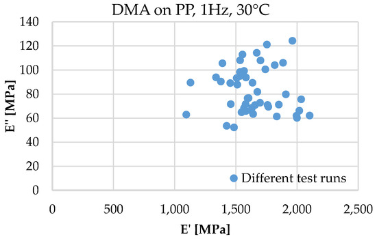
Figure 1.
Variation of DMA test results despite all PP, 1 Hz, 30 °C, span to thickness ratio >10, but different clamps, production methods, dimensions and isothermal step length.
The chosen trial material for the DMA in Texas Instruments’ Q800 was Polypropylene (PP). As possibly relevant influences on the testing result, five factors were considered:
- Clamp type
- Production method
- Span to thickness ratio (ST-Ratio)
- Width
- Isothermal step length
Even if stated in literature tensile clamps are only recommended for films and fibers [1,2], we chose to perform tests in that clamp as well, because the direction of loading were the same as our tensile creep test on dogbones. As second clamp single cantilever was chosen. For comparison selected production methods were extrusion and injection molding. For the span to thickness ratio a span of greater than 10 is recommended. For our trials, ratios of 10 and 16 were selected to validate if a ratio of 10 is sufficient.
Since the length in the single cantilever clamp is fixed, the thickness needed to be adapted. The extruded material could directly be produced in the required thicknesses of 1.0 mm and 1.8 mm. Injected bars were grinded down from 4 mm to the corresponding extruded thicknesses. The width was restricted by the clamps to maximum 10 mm. For the trials samples were cut to a width of 5 mm and 8 mm. Last considered factor is the length of the isothermal step; 3 min and 10 min were compared.
For the creep testing, Polyamide 6 was produced by injection molding. The material was chosen due to a higher glass transition temperature and therewith better expectable performance in the later application of a heat exchanger. For the DMA testing, bars are grinded down to a thickness of 1.7 mm and a width of 4 mm. Thereby water cooling was used to keep the surface temperature as low as possible. The rough surfaces were polished with a grain size up to 5 μm. For the creep test in the tensile machine, injected DIN EN ISO 527-2, type 1A [10] dogbones were used.
2.1. DMA
Setting up the DMA occurred according to the instructions of the machine manual and additional literature. The machine specific clamp calibration was performed at least once per day. The measurement of the length, especially in the single cantilever, was done manually after the setup was heated, because the middle clamp can move with slight pressure about 1 mm [8]. Since the length is equal to the stiffness multiplied by the geometry factor and in case of the cantilever the length is cubic in the formula [2], a small error in measurements changed the result of the modulus noticeably.
For the pre-study a single frequency sweep at 1 Hz and 30 °C was chosen. The strain was 0.05% in favor of staying in the pure viscoelastic region. In case of the tensile test a pre-stress of 0.01 N was applied to prevent buckling. According to statistics a half fractional factorial 25-design with three repetitions per test was performed. With the resulting value an univariate test with second order interactions was performed to find the significant factors influencing the DMA result, namely the tan δ, which was calculated from the loss and storage modulus [11].
2.2. Tensile Machine
The creep test on dogbones was performed in a common tensile machine (Instron R5800) with heat chamber. Instead of using the load control setting, which leads to an overshooting of the desired load, a constant load was placed on the cross head and fixed on the sample. By moving the crosshead with a given speed, the loading phase has been defined and ends when the sample was fully loaded. Strain measurement was performed with 3D-DIC through the glass of the heat chamber. With comparing the strain to an extensometer at room temperature it can be ensured the glass has no falsifying distortion effect, see Figure 2.
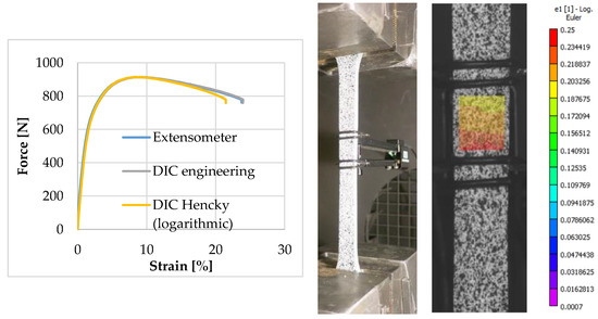
Figure 2.
Comparison of DIC and extensometer measurement, good result until Fmax.
3. Results
The normal distributed results indicate, DMA testing is sensitive to many factors. With a confidence interval of 95%, all main factors are considered as significant except for the isothermal step length. Especially the choice of the clamps cause a strong variation of the results as displayed in the boxplot Figure 3. Notable intersection is evidenced in Figure 4 and occurs according to the F-value between the production method and the span-to-thickness-ratio.
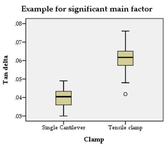
Figure 3.
Boxplot diagram showing the influence of the clamp type on the resulting tan delta in DMA.
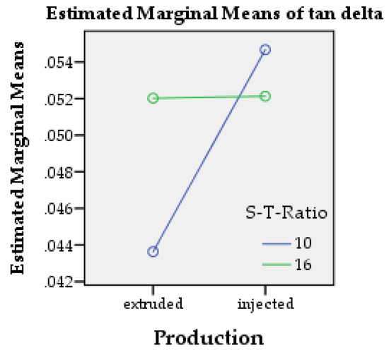
Figure 4.
Profile plot picturing the intersection between production method and span-to-thickness ratio.
Even if the issue of influencing factors is not entirely solved yet, a DMA creep test was performed on PA6 as an example. A loading of 1 h with subsequent 2 h relaxation was performed on a strain level of 0.01% (Figure 5). On larger scale, tensile creep tests were performed to generate a master curve through a curve shift. The result is shown in Figure 6.
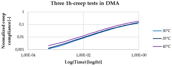
Figure 5.
Creep curve of PA6, performed from 30 °C until 40 °C in 5 °C steps created from DMA test with a load according to 0.1% of the tensile strain at a strain rate of 10−5 s−1.
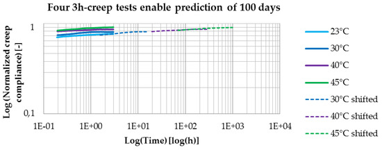
Figure 6.
Master curve for PA6 created from tensile curves according to a load of 1% of the tensile strain at a strain rate of 10−5 s−1.
4. Discussion
Due to the strong scattering of the results, no clear trend could be detected. The clamp type had a significant influence because of the different type of loading applied to the sample. It was expected to notice an interaction between the dimensions of the sample and the clamp type which did not occur. Maybe the differences of width or ST-Ratio were too small to spot a significant interaction. A higher ratio or a smaller width in the tensile clamp might enable the usage.
The significant influence of the production method is unlikely caused by the production itself since the polymer grade is the same. Supposable, the post processing has an influence due to eventual different surface roughness, edges or thermal influence due to grinding.
Only the length of the isothermal step seems to have no influence on the result. The heating speed of 2 °C/min and the subsequent isothermal step of 3 min respectively 10 min seem to be enough to heat the sample through. It is supposed that 3 min is long enough to heat the sample entirely through. For time saving purposes, a shorter time step or faster heating could be tried.
Due to the missing of a clear trend, it is assumed that important factors were disregarded until now. Another potential source of error might be for example the clamping angle. With horizontal laser lines the procedure was tried to be improved (see Figure 7), but also due to the fragile clamp, torsion is not entirely excludable.
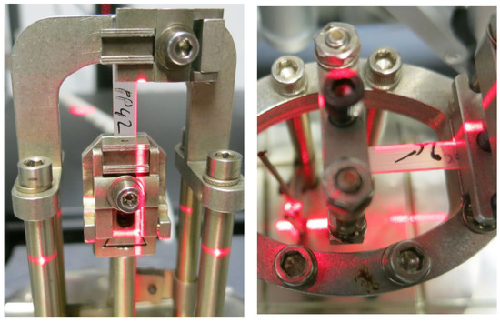
Figure 7.
Aligned laser lines for straighter sample mounting in tensile clamp and single cantilever.
With further investigation it will be hopefully possible to find a general method to be certain about the accuracy of the gained results. Afterwards creep curves like the one showed in Figure 5 can be monitored. In combination with the shifted creep curves from the tensile setup, it should then be possible to generate load dependent long-term predictions for the material.
5. Conclusions
Influences on the procedure of dynamic mechanical analysis were examined. A statistic approach showed a heating speed of 2 °C/min plus an isothermal step of 3 min is sufficient to heat the sample core. Other results from the statistical analysis are, DMA is highly sensitive to several parameter such as clamp type, sample dimensions and preparation method of the sample. A solution to overcome the instability in measurements will have to be found in the future. After solving those issues, it should be possible to compare creep tests in DMA with creep tests from the tensile machine. With the usage of the time temperature superposition principle, the performance of PA6 can be predicted for at least 100 days by only performing 12 h of testing. Further investigations will follow.
Author Contributions
W.V.P., A.K. and J.S. conceived and designed the experiments; J.S. performed the experiments and analyzed the data; T.W. contributed materials, W.V.P. analysis tools; J.S. wrote the paper.
Acknowledgments
This research was supported by the VLAIO SBO-150013 project Composite Heat Exchangers (www.compohex.ugent.be) funded by Flanders Innovation & Entrepreneurship (VLAIO). The financial supports are gratefully acknowledged. We also thank Lode Daelemans for his support in DMA and Helix Van Leynseele for her support in the tensile creep tests.
Conflicts of Interest
The authors declare no conflict of interest. The founding sponsors had no role in the design of the study; in the collection, analyses, or interpretation of data; in the writing of the manuscript, and in the decision to publish the results.
References
- PerkinElmer. A Beginner’s Guide: Dynamic Mechanical Analysis; PerkinElmer: Waltham, MA, USA, 2008. [Google Scholar]
- TAInstruments. Dynamic Mechanical Analyse; TA Instruments: New Castle, DE, USA, 2016. [Google Scholar]
- Tajvidi, M.; Falk, R.H.; Hermanson, J.C. Time–temperature superposition principle applied to a kenaf-fiber/high-density polyethylene composite. J. Appl. Polym. Sci. 2005, 97, 1995–2004. [Google Scholar] [CrossRef]
- ASTM International. ASTMD6992-03: Accelerated Tensile Creep and Creep-Rupture of Geosynthetic Materials Based on Time-Temperature Superposition Using the Stepped Isothermal Method; ASTM International: West Conshohocken, PA, USA, 2015. [Google Scholar]
- ASTM International. ASTM International. ASTM D5026: Standard Test Method for Plastics: Dynamic Mechanical Properties. In Tension; ASTM International: West Conshohocken, PA, USA, 2015. [Google Scholar]
- ASTM International. ASTM International. ASTM D5418-15: Standard Test Method for Plastics: Dynamic Mechanical Properties. In Flexure (Dual Cantilever Beam); ASTM International: West Conshohocken, PA, USA, 2015. [Google Scholar]
- Gabbott, P. Principes and Applications of Thermal Analysis; Blackwell Publishing: Hoboken, NJ, USA, 2008. [Google Scholar]
- McAninch, I.M.; Palmese, G.R.; Lenhart, J.L.; La Scala, J.J. DMA testing of epoxy resins: The importance of dimensions. 2015, 55, 2761–2774. [Google Scholar] [CrossRef]
- ASTM international. ASTM D790-10 Standard Test Methods for Flexural Properties of Unreinforced and Reinforced Plastics and Electrical Insulating Materials; ASTM international: West Conshohocken, PA, USA, 2010. [Google Scholar]
- DIN Deutsches Institut für Normung. DIN EN ISO 527-2: Bestimmung der Zugeigenschaften Teil 2; Prüfbedingungen für Form- und Extrusionsmassen; DIN Deutsches Institut für Normung e.V.: Berlin, Germany, 2012. [Google Scholar]
- Menard, K.P. Dynamic Mechanical Analysis: A Practical Introduction; CRC Press: Boca Raton, FL, USA, 2008. [Google Scholar]
Publisher’s Note: MDPI stays neutral with regard to jurisdictional claims in published maps and institutional affiliations. |
© 2018 by the authors. Licensee MDPI, Basel, Switzerland. This article is an open access article distributed under the terms and conditions of the Creative Commons Attribution (CC BY) license (https://creativecommons.org/licenses/by/4.0/).