Proceeding Paper

Performance Evaluation of Microtubular Solid Oxide Fuel Cell Prototypes at a Laboratory Scale and Identification of Needs Related to Gas Sensors †

by
César I. Ramos Villegas
1,
Carlos L. Fernández Rendón
2 and
Hugo J. Avila-Paredes
1,*
1
Department of Hydraulic and Processes Engineering, Metropolitan Autonomous University, Iztapalapa Campus, Av. San Rafael Atlixco 186, Colonia Vicentina, Mexico City 09340, Mexico
2
Graduate program in Energy and Environment, Metropolitan Autonomous University, Iztapalapa Campus, Av. San Rafael Atlixco 186, Colonia Vicentina, Mexico City 09340, Mexico
*
Author to whom correspondence should be addressed.
Presented at the 4th International Electronic Conference on Sensors and Applications, 15–30 November 2017; Available online: http://sciforum.net/conference/ecsa-4.
Proceedings 2018, 2(3), 106; https://doi.org/10.3390/ecsa-4-04910
Published: 14 November 2017

Abstract

:
Solid Oxide Fuel Cells (SOFC’s) are devices for power generation, usually for stationary applications. Microtubular SOFC’s have been developed for portable applications. The present contribution includes a brief description of the fabrication and some results of the performance evaluation of microtubular SOFC’s (specifically for samples that are in the process of failing due to the formation of fractures in them or in the cement sealant) at a laboratory scale so that researchers who are developing sensors could improve their prototypes for this type of applications. During the evaluation, safety relies on gas sensors that detect fuel leaks. A low cost hydrogen gas detector—alarm system is also presented.

1. Introduction

Solid Oxide Fuel Cells (SOFC’s) are electrochemical devices for the conversion of chemical energy from fuels into electrical energy. They are mainly used in stationary applications due to their high efficiencies (~60%, or higher when used in cogeneration) and high operating temperatures (~1000 °C). Other features of these devices are: a noiseless operation, flexibility in the type of fuel to utilize (e.g., hydrogen, methane, ethanol), a modular use in power generation systems as to meet the electrical power requirements, lower environmental impact vs. that of conventional thermoelectric power generation based on their high efficiencies, components are made of ceramic materials (i.e., solid oxides) [1].
As in any electrochemical cell, SOFC’s are composed by an electrolyte and two electrodes. When using hydrogen as fuel and the electrolyte is an oxygen ion conductor, air is usually fed to the cathode chamber, so that oxygen is reduced at the porous cathode (Equation (1)); the produced oxygen ions migrate from cathode to the anode through the dense electrolyte; at the surface of the porous anode, oxygen ions react with hydrogen (fed to the anode chamber) to produce water and electrons that are conducted through an external circuit, from anode to cathode.
1 2 O 2 + 2 e O 2
O 2 + H 2 H 2 O + 2 e
Different SOFC architectures have been developed: planar, tubular and monolithic [1,2,3], based on the ease of (1) fabrication of the layers of the ceramic materials that constitute the anode/electrolyte/cathode (the thinner they are, the better since the corresponding ohmic resistance would be lower, however materials strength is compromised with thickness); (2) integration of those layers, considering also interconnectors (for application, a system of many cells, connected in series and parallel, should be fabricated); and (3) sealing the cathode and anode chambers so that fuel is not mixed with air, they should be separated for the SOFC’s to correctly operate. Microtubular SOFC’s have been proposed for portable or mobile applications [4,5,6]. Devices with this particular architecture have relatively small dimensions: length of tubes less than 10 cm, diameter less than 5 mm and thickness of the cell components in the sub-micrometer range. Due to their small size, the temperature gradients in the stack could be relatively low, so that stacks of microtubular SOFC’s have greater tolerance to thermal cycling, high resistance to thermal shock, faster start-up capability, besides higher volumetric power density and the ease of sealing, compared to conventional tubular SOFC’s. The main fabrication techniques to produce microtubular SOFC’s are extrusion, dip coating and could be coupled with some others such as electrochemical vapor deposition and thermal spraying [7,8,9,10,11]; sintering processes are usually performed alternately.
Based on the works by De la Torre et al. [9,10,11], we started working on the development of microtubular SOFC prototypes at a laboratory scale. Usually performance evaluation of the cells is conducted using hydrogen (5 or 10% H2 in argon, or 100% H2 saturated with water at room temperature [12,13,14]) as fuel, and cells are placed within a tubular furnace which is in the 500–700 °C range. Hydrogen flows in the inside of the tubular cells while stagnant air is surrounding the cell. The performance evaluation of the prototypes is usually done based on Linear Sweep Voltammetry and Electrochemical Impedance Spectroscopic measurements; results of those techniques can indicate that there are leaks in the sealing or that fractures in samples are being propagated. Some of those results are shown in this contribution.
In this scenario, safety significantly relies on hydrogen detecting sensors. There is a variety of types of commercial hydrogen sensors (electrochemical, metal oxide, pellistor, optical, etc.) based on their working principle [15,16,17]. In terms of research, design and development of materials for such sensors are under progress [18,19,20] (e.g., flexible materials [19]). Sensitivity, interferences and poisoning [20] are important factors to be considered for the selection of an adequate sensor.
We also present the design of a low cost system for hydrogen detection, containing visual alarms (RGB LEDs) and a buzzer: two hydrogen sensors were included and placed closed to the ends of the tubular furnace.

2. Materials and Methods

2.1. Fabrication and Performance Evaluation of Microtubular SOFC Prototypes

Microtubular SOFC prototypes were fabricated based on a dip coating technique: electrolytic and electrodic suspensions were prepared from commercial ceramic powders (Ce0.8Gd0.2O1.95, GDC20-M, fuelcellmaterials; 50 wt% NiO-50 wt% Ce0.8Gd0.2O1.95, GDC20-M, fuelcellmaterials; La0.8Sr0.2Co0.2Fe0.8O3, LSCF-P, fuelcellmaterials) and an ink vehicle (fuelcellmaterials). Polymethylmethacrylate cylindrical rods (diameter ~1.14 mm, length ~3 cm, Goodfellow) were used as sacrificial cores; they were dip coated (ND-DC Nadetech Innovations dip coater) with the anodic suspension (containing NiO and Ce0.8Gd0.2O1.95: NiO-GDC), drying alternately at 100 °C for 1 h, until a thickness of ~0.5 mm was reached. Then an electrolyte layer (GDC) was applied by dip coating. After drying, sintering at 1420 °C for 8 h was performed. During this process the sacrificial core was decomposed. The cathodic suspension (containing La0.8Sr0.2Co0.2Fe0.8O3: LSCF) was applied by brush painting and dried at room temperature for 24 h. A final sintering was performed at 1150 °C for 2 h. Silver wires were wound around the exposed cathodic (at the center) and anodic (extremes) parts and silver paint was applied, thus forming the current collectors. The cells were then connected into alumina tubes and a cement sealant was applied (Ceramabond 885). A thermal treatment at 260 and 370 °C for 2 h was carried out. Reduction of anode was performed at 500 °C for 2 h with a 5 mL/min H2 flow (saturated with water at room temperature). During this process, the Open Circuit Voltage of the cell (OCV) was measured. Once the OCV is close to 1 V and steady, Linear Sweep Voltammetry (LSV), followed by Electrochemical Impedance Spectroscopic (EIS) measurements were performed. From LSV measurements (from OCV to 0 V, at a 10 mV/s rate) polarization curves (cell voltage vs current density and power density vs current density; power density was estimated as the product of cell voltage times current density) were obtained. EIS measurements were made with an applied voltage signal with an amplitude of 10 mV in the 8 × 10⁻³ to 1 × 10⁶ Hz frequency range.

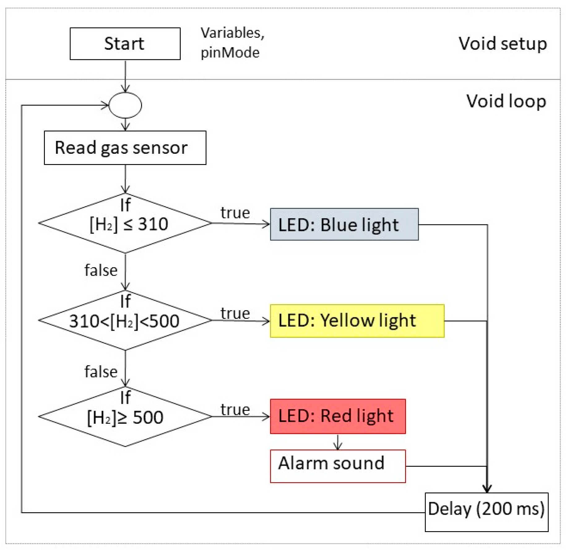
2.2. Design of a Hydrogen Detecting—Alarm System

The hydrogen detecting system was composed of two MQ-8 gas sensors (Zhengzhou Winsen Electronics Technology, Zhengzhou, China) connected to an Arduino board with an expansion shield. The alarm module of the system included two RGB LEDs and one buzzer. Each gas sensor, together with a RGB LED, was placed close to the ends of the tubular furnace used for the performance evaluation of the cells. The structure of the code for the Arduino board is shown in Figure 1; [H2] represents the hydrogen concentration (ppm) detected by the sensor. Depending on the hydrogen concentration value that is read every 200 ms, a certain color (blue, yellow or red) is displayed on the LED and when red is displayed, the buzzer emits simultaneously an alarm sound. Before use, gas sensors were calibrated with a flow of pure hydrogen.

3. Results and Discussion

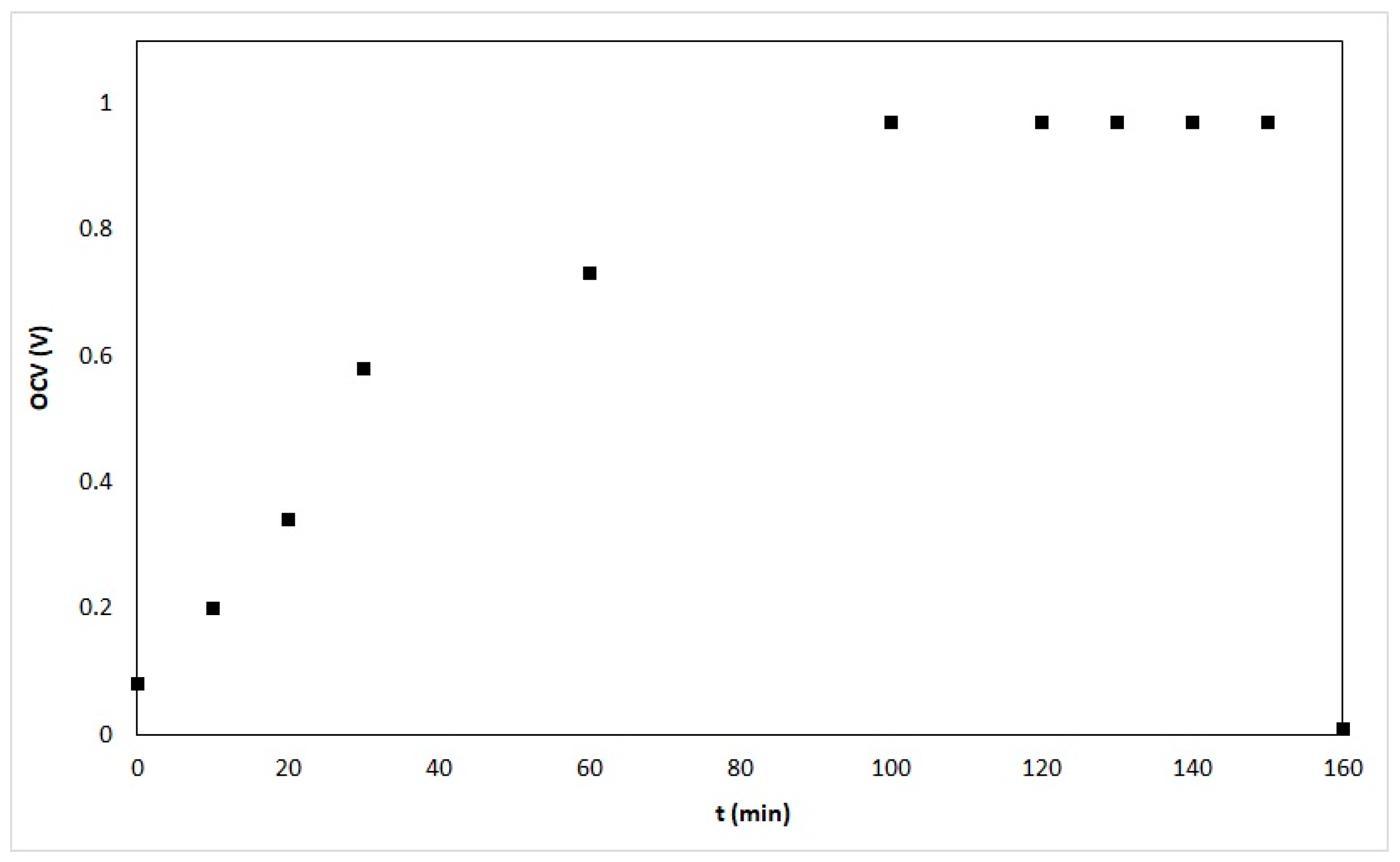
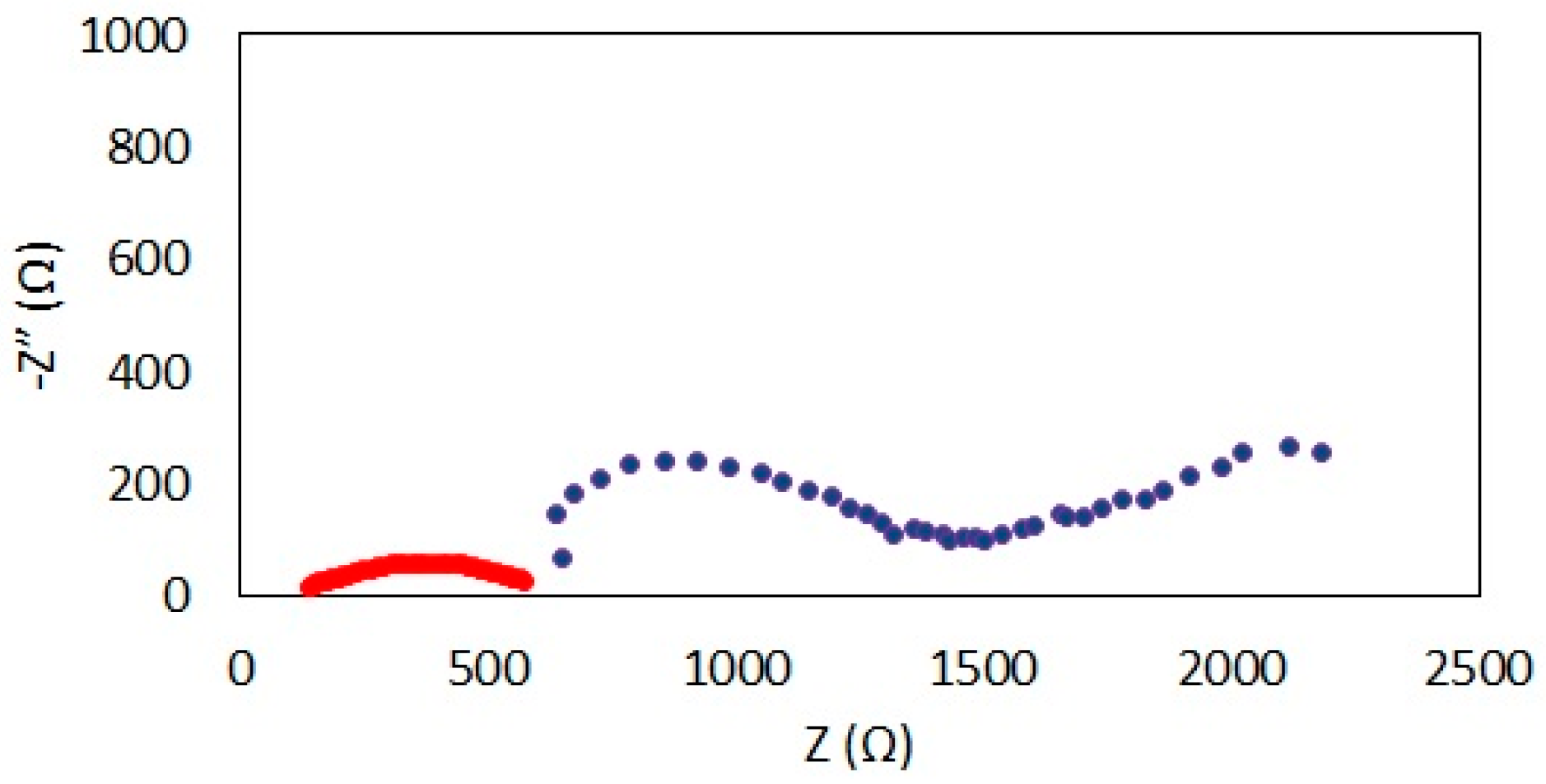
3.1. Performance Evaluation of Microtubular SOFC Prototypes

Results in this section correspond to a microtubular SOFC prototype (NiO-GDC/GDC/LSFC) with a length of ~2 cm, an outer diameter of ~1.5 mm; the anode, electrolyte and cathode thicknesses were ~350, 15 and 40 μm, respectively. It is important to mention that after the thermal treatment for curing the sealant, air or nitrogen is passed through the prototypes and the flow is measured before and after the samples, to ensure that the sealant has no leaks. The OCV values of the NiO-GDC/GDC/LSFC prototype during reduction are shown in Figure 2.
When there are small leaks of hydrogen, the OCV value does not approximate to ~1 V. Some samples could have microcracks that propagate during the thermal treatments and cause hydrogen leaks.
After the 2 h of started the anode reduction at 500 °C, LSV measurements were performed on the NiO-GDC/GDC/LSFC prototype. About one hour later, the OCV was decreased; LSV measurements were performed again. The LED of the hydrogen detecting system indicated the presence of hydrogen outside of the furnace. After cooling down the furnace, the prototype showed a significant cross-sectional fracture. Figure 3 shows the corresponding polarization curves.
On the polarization curves shown in Figure 3a, the OCV is ~1 V, the maximum power density ~300 mW/cm2, at a current density of ~830 mA/cm2 and a cell voltage of ~0.38 V. The values of all of the mentioned parameters significantly dropped when the sample was fractured and hydrogen mixed directly with oxygen: OCV was ~0.84 V, maximum power density ~9 mW/cm2 at a current density of ~2.8 mA/cm2 and a cell voltage of ~0.05 V.
The impedance spectra in a Nyquist plot format are shown in Figure 4. It is evident that the impedance of the sample was significantly increased due to the fracture.
As already shown, the results of the electrical measurements could indicate the propagation of fractures in samples, as well as the occurrence of hydrogen leaks. However, in terms of safety it is important to have a hydrogen detecting—alarm system, with sensors as close as possible to the places where hydrogen leaks could happen. If possible, it would be better to place sensors inside the furnace; in this case, a relatively high sensitivity to detect hydrogen in air is needed. As SOFC’s could operate with other fuels, sensors for detecting hydrocarbons are also needed in this research area.

3.2. Design of a Hydrogen Detecting—Alarm System

The already described system has the advantages of low cost (~45 USD) and several hydrogen sensors can be connected with minor modifications of the software. MQ-8 sensors detect hydrogen in air in the 100–10,000 ppm range (much lower than the Lower Flammability Limit of hydrogen in air, i.e., 4%) and could be used for detecting other gases (e.g., alcohol [21]). The system has also the flexibility of using other sensors (if sensibility for other gases becomes an issue). Sensors have to be placed outside the furnace since their operating temperature range is −110 to 50 °C.

4. Conclusions

Results from LSV and EIS measurements could predict or be indicative of total failure in microtubular SOFCs: Low OCV, low maximum power densities values indicate that hydrogen is mixed with oxygen; an increase of impedance of the samples at constant conditions could indicate propagation of fractures. However, safety related to hydrogen use, during performance evaluation of prototypes at a laboratory scale, should rely on monitoring systems with alarms. Sensors included in those systems should have high sensitivity and the best would be to place them as close as possible to where fractures and leaks could happen, bearing in mind that intermediate temperature fuel cells operate in the 500–700 °C range. A low cost hydrogen detecting system was developed and is being used: it has the advantage that more than one sensor could be connected to it, it has RGB LEDs as indicators of the hydrogen concentration and a buzzer that is activated when a certain concentration is surpassed. The system can easily be modified to use other type of gas sensors.

Author Contributions

C.I.R.V. performed the experiments related to the fabrication and performance evaluation of microtubular SOFC prototypes. C.L.F.R. designed, constructed, calibrated and evaluated the operation of the hydrogen detecting—alarm system. All 3 authors wrote the paper.

Acknowledgments

Funding for this research was provided by Ministery of Science, Technology and Innovation of Mexico City (Secretaría de Ciencia, Tecnología e Innovación del Distrito Federal, SECITI-DF; project PICSO 12-060) and Universidad Autónoma Metropolitana Unidad Iztapalapa (project “Desarrollo de prototipos y diseño de celdas de combustible”). C.I.R.V. and C.L.F.R. are thankful to Consejo Nacional de Ciencia y Tecnología for the scholarship received to pursue their studies.

Conflicts of Interest

The authors declare no conflict of interest. The funding sponsors had no role in the design of the study; in the collection, analyses, or interpretation of data; in the writing of the manuscript, and in the decision to publish the results.

References

  1. Li, X. Principles of Fuel Cell, 1st ed.; Taylor and Francis: New York, NY, USA, 2006; pp. 4–14, 21–29. ISBN 1591690226, 9781591690221. [Google Scholar]
  2. Timurkutluk, B.; Timurkutluk, C.; Mat, M.D.; Kaplan, Y. A review on cell/stack designs for high performance solid oxide fuel cells. Renew. Sustain. Energy Rev. 2016, 56, 1101–1121. [Google Scholar] [CrossRef]
  3. Stambouli, A.B.; Traversa, E. Solid oxide fuel cells (SOFCs): A review of an environmentally clean and efficient source of energy. Renew. Sustain. Energy Rev. 2002, 6, 433–455. [Google Scholar] [CrossRef]
  4. Yang, C.; Jin, C.; Chen, F. Micro-tubular solid oxide fuel cells fabricated by phase-inversion method. Electrochem. Commun. 2010, 12, 657–660. [Google Scholar] [CrossRef]
  5. Howe, K.S.; Thompson, G.J.; Kendall, K. Micro-tubular solid oxide fuel cells and stacks. J. Power Sources 2011, 196, 1677–1686. [Google Scholar] [CrossRef]
  6. Yamaguchi, T.; Galloway, K.V.; Yoon, J.; Sammes, N.M. Electrochemical characterizations of microtubular solid oxide fuel cells under a long-term testing at intermediate temperature operation. J. Power Sources 2011, 196, 2627–2630. [Google Scholar] [CrossRef]
  7. Jamil, S.M.; Othman, M.H.D.; Rahman, M.A.; Jaafar, J.; Ismail, A.F.; Li, K. Recent fabrication techniques for micro-tubular solid oxide fuel cell support: A review. J. Eur. Ceram. Soc. 2015, 35, 1–22. [Google Scholar] [CrossRef]
  8. Chen, C.; Liu, M.; Yang, L.; Liu, M. Anode-supported micro-tubular SOFCs fabricated by a phase-inversion and dip-coating process. Int. J. Hydrog. Energy 2011, 36, 5604–5610. [Google Scholar] [CrossRef]
  9. De la Torre, R. Production of Micro-Tubular Solid Oxide Fuel Cells. Ph.D. Thesis, Department of Materials Engineering and Industrial Technologies, University of Trento, Trento, Italy, April 2011. [Google Scholar]
  10. De la Torre, R.; Sglavo, V.M. Fabrication of innovative compliant current collector- supported microtubular solid oxide fuel cells. Int. J. Appl. Ceram. Technol. 2012, 9, 1058–1063. [Google Scholar] [CrossRef]
  11. De la Torre, R.; Avila-Paredes, H.J.; Sglavo, V.M. Comparative performance analysis of anode-supported micro-tubular SOFCs with different current collection architectures. Fuel Cells 2013, 13, 729–732. [Google Scholar] [CrossRef]
  12. Suzuki, T.; Funahashi, Y.; Hasan, Z.; Yamaguchi, T.; Fujishiro, Y.; Awano, M. Fabrication of needle-type micro SOFCs for micro power devices. Electrochem. Commun. 2008, 10, 1563–1566. [Google Scholar] [CrossRef]
  13. Singhal, S.C. Advances in solid oxide fuel cell technology. Solid State Ion. 2000, 135, 305–313. [Google Scholar] [CrossRef]
  14. Campana, R.; Larrea, A.; Merino, R.I.; Villareal, I.; Orera, V.M. SOFC mini-tubulares basadas en YSZ. Bol. Soc. Esp. Ceram. Vidr. 2008, 47, 189–195. [Google Scholar] [CrossRef]
  15. Buttner, W.J.; Post, M.B.; Burgess, R.; Rivkin, C. An overview of hydrogen safety sensors and requirements. Int. J. Hydrog. Energy 2011, 36, 2462–2470. [Google Scholar] [CrossRef]
  16. Hübert, T.; Boon-Brett, L.; Black, G.; Banach, U. Hydrogen sensors—A review. Sens. Actuators B Chem. 2011, 157, 329–352. [Google Scholar] [CrossRef]
  17. Hübert, T.; Boon-Brett, L.; Palmisano, V.; Bader, M.A. Developments in gas sensor technology for hydrogen safety. Int. J. Hydrog. Energy 2014, 39, 20474–20483. [Google Scholar] [CrossRef]
  18. Luo, Y.; Zhang, C.; Zheng, B.; Geng, X.; Debliquy, M. Hydrogen sensors based on noble metal doped metal-oxide semiconductor: A review. Int. J. Hydrog. Energy 2017, 42, 20386–20397. [Google Scholar] [CrossRef]
  19. Chung, M.G.; Kim, D.H.; Seo, D.K.; Kim, T.; Im, H.U.; Lee, H.M.; Yoo, J.B.; Hong, S.H.; Kang, T.J.; Kim, Y.H. Flexible hydrogen sensors using graphene with palladium nanoparticle decoration. Sens. Actuators B Chem. 2012, 169, 387–392. [Google Scholar] [CrossRef]
  20. Palmisano, V.; Weidner, E.; Boon-Brett, L.; Bonato, C.; Harskamp, F.; Moretto, P.; Post, M.B.; Burgess, B.; Rivkin, C.; Buttner, W.J. Selectivity and resistance to poisons of commercial hydrogen sensors. Int. J. Hydrog. Energy 2015, 40, 11740–11747. [Google Scholar] [CrossRef]
  21. Flammable Gas Sensor (Model; MQ-8) Manual. Available online: https://cdn.sparkfun.com/datasheets/Sensors/Biometric/MQ-8%20Ver1.3%20-%20Manual.pdf (accessed on 30 October 2017).
Figure 1. Flowchart of the software for the hydrogen detecting-alarm system.
Proceedings 02 00106 g001
Figure 2. Evolution of the OCV during anode reduction.
Proceedings 02 00106 g002
Figure 3. Polarization curves of a microtubular SOFC prototype at 500 °C, (a) at a stable OCV and (b) after a hydrogen leak was detected.
Proceedings 02 00106 g003
Figure 4. Nyquist plots of a microtubular SOFC prototype at 500 °C, before (red) and after (blue) a hydrogen leak ocurred.
Proceedings 02 00106 g004
Publisher’s Note: MDPI stays neutral with regard to jurisdictional claims in published maps and institutional affiliations.

