Proceeding Paper

A Computational Study on the Damping-Amplitude Dependence and Estimation of the Limit Cycle Oscillations for Normal Triangular Arrays with One Tube Undergoing Fluidelastic Instability †

Energy Department, Oviedo University, 33205 Oviedo, Spain
*
Author to whom correspondence should be addressed.
Presented at the 2nd International Research Conference on Sustainable Energy, Engineering, Materials and Environment (IRCSEEME), Mieres, Spain, 25–27 July 2018.
Proceedings 2018, 2(23), 1498; https://doi.org/10.3390/proceedings2231498
Published: 7 November 2018

Abstract

:
While the estimation of the critical velocity for fluidelastic instability of tube arrays has received considerable attention for decades, the studies intended to analyze the post-stable behavior have been scarce. However, the behavior of the system under instability, is also interesting in order to characterize the amount of energy transferred from fluid to structure. A computational study has been carried out for the case of one tube vibrating in a normal triangular array by means of a CFD model previously developed with Fluent by the authors. This model incorporates the motion of the vibrating tube by means of user defined functions for both forced and free oscillations, so that the tube position can be updated and the mesh rebuilt at every time step. First, predictions of limit-cycle oscillations (zero net damping) were obtained for pitch ratios P/d = 1.25 and 1.375, so that the experimental response curves (amplitude against flow velocity) measured in other experimental studies could be used for contrast purposes. After validation, the CFD model was used to investigate how the net damping of the fluid-structure system depends on the vibration amplitude for a given flow velocity, which shows the non-linear nature of the tube response. Finally, special simulation series were conducted to explore the effects of pitch ratio, Reynolds number and structural damping on the net damping of the system for constant vibration amplitude.

1. Introduction

Tube arrays subject to cross flow may exhibit large amplitude selfexcited vibrations referredtoas Fluidelastic Instability (FEI). In damping controlled FEI, although only a single structural degree of freedom is needed, the fluid dynamics are inherently unsteady. Amplitude of vibration maintains constant at a certain value when the total net damping (structural plus fluid) reduces to zero, this amplitude value is called limit cycle oscillation LCO. LCO increases with cross flow velocity, for a sufficiently high amplitude value, involving risk of damaging the equipment, the system is considered. A typical value to stablish this limit is 2% of tube diameter. Apart of security considerations, for which analyzing the stable regime evolution towards the zero damping point would be sufficient, the FEI phenomena opens the possibility of a controlled extraction of energy from the flow in unstable regime. In this case, analyzing amplitude of vibration evolution at increasing cross flow velocities would be the basis of a future renewable energy study based on FEI phenomenon. the behavior of the system under instability, which is non-linear (Meskell and Fitzpatric, 2003) [1], would allow for the calculation of the energy transferred from the fluid to the tube array.
Here, a series of simulations using a dynamic-mesh URANS solver for increasing amplitudes crossing the stability threshold are carried out in free motion conditions (de Pedro et al., 2016) [2]. The free response of tube response allows the limit cycle oscillation amplitude to be calculated and hence the amplitu-velocity curves can be obtained. Finally, the non-linear nature of the FEI phenomenon is numerically predicted [1].

2. Numerical Domain and Mesh

Numerical domain consisted in a normal triangular tube array subject to an air cross flow in which one tube is allowed to vibrate freely, geometry of the tube array is shown in Figure 1. This same geometry was previously tested by the authors and compared to experimental data at several stages (Mahon and Meskell, 2009 and 2013, [3,4], Austermann and Popp (1995) [5] and Sawadogo and Mureithi, 2013 [6]), details of the parameters, sensitivity tests and validation can be found in [2]. Figure 2 shows a detail of the deforming mesh used in this series of simulations.

3. CFD Methodology for LCO Determination

Series of simulations setting the tube free at different amplitudes were carried out and tube trajectory analyzed. LCO is determined to be in the range for which net damping changes from negative to positive. Figure 3 shows the prediction methodology.

4. Results

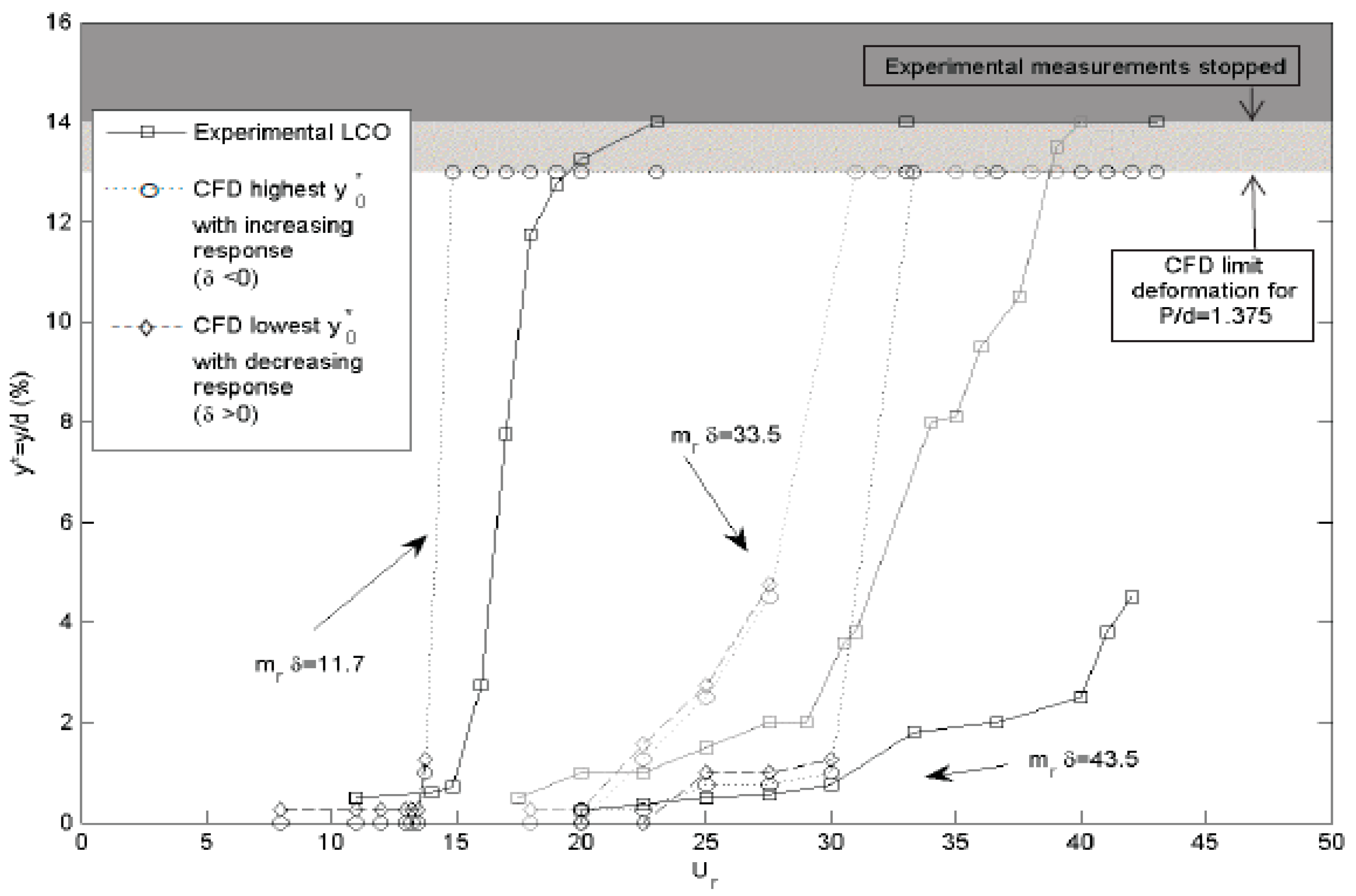
With the described methodology LCO were estimated for two different P/d arrays, 1.25 and 1.375, corresponding to those used by Austermann and Popp in their experimental study [5]. Figure 4 and Figure 5 shows results obtained in comparison to experimental data. As can be seen the methodology lightly under predict LCO in the stable regime while in unstable regime (for high amplitudes) the CFD overpredicts the real amplitude observed empirically. This behavior may be attributed to the turbulence present in an experimental determination, where very low amplitudes observed in the CFD cant take place physically. On the other side this same turbulence interfere in the coherence between tube motion and the coupled flow, contributing to reduce the LCO amplitude in the unstable regime while compared to a numerical result.
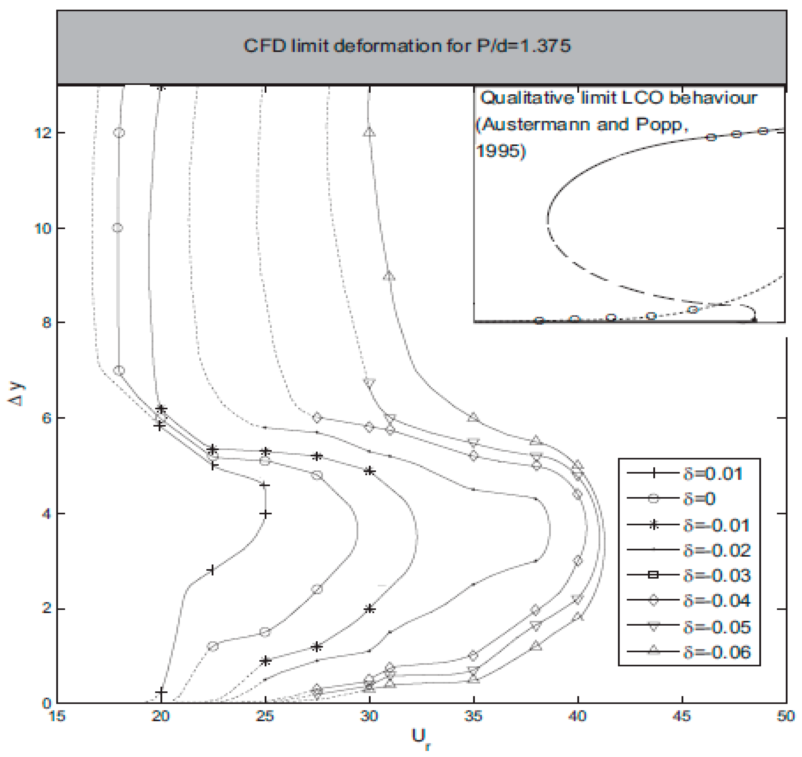
Finally amplitude-velocity curves were calculated for different damping values, Figure 6 shows results obtained as well as [5] expected qualitative behavior, those results, although being still preliminary are also in agreement to the non linear behavior demonstrated by [1] and to the multiple stability thresholds predicted by Leaver and Weaver model [7,8] and are considered promising enough to be extended in future studies.

5. Conclusions

A novel CFD methodology for the prediction of LCO under FEI has been proposed. Specific conclusions obtained in the present study can be summarized as follows:
  • The methodology lightly under predict LCO in the stable regime while in unstable regime (for high amplitudes) the CFD overpredicts the real amplitude observed empirically. This behavior may be attributed to the turbulence present in an experimental determination, where very low amplitudes observed in the CFD cant take place physically. On the other side this same turbulence interfere in the coherence between tube motion and the coupled flow, contributing to reduce the LCO amplitude in the unstable regime while compared to a numerical result.
  • The methodology was applied to predict the amplitude-velocity curves and was found to produce similar qualitative results than those proposed by several authors in the literature [1,3,4,5]. Although the study is still ongoing the methodology in considered interesting to analyze the net damping behavior in unstable conditions in future studies.

Author Contributions

B.d.P. and J.P. conceived and designed the CFD campaing; J.T. performed CFD tests in the experimental conditions of the parallel empirical investigation line; G.L. contributed theoretical analysis tools; B.d.P. wrote the paper.

Acknowledgments

The authors gratefully acknowledge the financial support received from the Spanish Ministry of Economy and Competitiveness (project MCE-DPI-2012-36464) as well as the PhD grant BP-12054 awarded to Ms. de Pedro by the Principality of Asturias Government.

Conflicts of Interest

The founding sponsors had no role in the design of the study; in the collection, analyses, or interpretation of data; in the writing of the manuscript, and in the decision to publish the results.

References

  1. Meskell, C.; Fitzpatric, J.A. Investigation of the nonlinear behaviour of damping controlled fluidelastic instability in a normal triangular tube array. J. Fluids Struct. 2003, 18, 573–593. [Google Scholar] [CrossRef]
  2. de Pedro, B.; Parrondo, J.; Meskell, C.; Fernández-Oro, J. CFD modelling of the cross-flow through normal triangular tube arrays with one tube undergoing forced vibrations or fluidelastic instability. J. Fluids Struct. 2016, 64, 67–86. [Google Scholar] [CrossRef]
  3. Mahon, J.; Meskell, C. Surface pressure distribution survey in normal triangular tube arrays. J. Fluids Struct. 2009, 25, 1348–1368. [Google Scholar] [CrossRef]
  4. Mahon, J.; Meskell, C. Estimation of the time delay associated with damping controlled fluidelastic instability in a normal triangular tube array. J. Press. Vessel Technol. 2013, 135, 030903. [Google Scholar] [CrossRef]
  5. Austermann, R.; Popp, K. Stability Behaviour of a Single Flexible Cylinder in Rigid Tube Arrays of Different Geometry Subjected to Cross-Flow. J. Fluids Struct. 1999, 9, 303–322. [Google Scholar] [CrossRef]
  6. Sawadogo, T.; Mureithi, N. Time domain simulation of the vibration of a steam generator tube subjected to fluidelastic forces induced by two phase cross-flow. J. Press. Vessel Technol. 2013, 135, 030905. [Google Scholar] [CrossRef]
  7. Lever, J.; Weaver, D. On the stability of heat exchanger tube bundles. Part I: Modified theoretical model. J. Sound Vib. 1986, 107, 375–392. [Google Scholar] [CrossRef]
  8. Lever, J.; Weaver, D. On the stability of heat exchanger tube bundles. Part II: Numerical results and comparison with experiments. J. Sound Vib. 1986, 107, 393–410. [Google Scholar] [CrossRef]
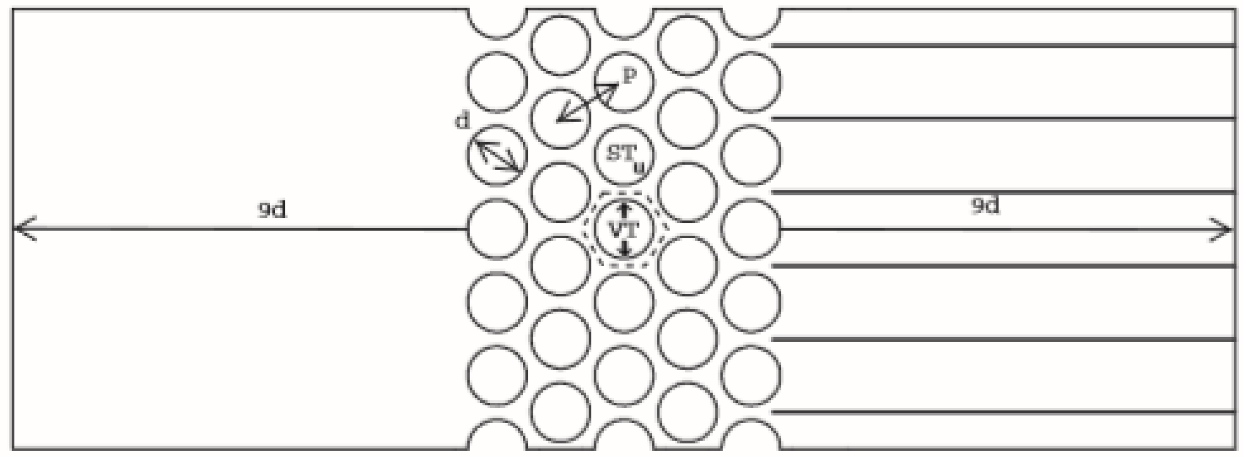
Figure 1. Characteristics of the computational domain used in this series of simulations.
Proceedings 02 01498 g001
Figure 2. Detail of the dynamic mesh allowing for tube motion.
Proceedings 02 01498 g002
Figure 3. LCO prediction: (a) Numerical sequence (b) Limit cycle oscillation predicted interval.
Proceedings 02 01498 g003
Figure 4. LCO predicted for P/d = 1.25 tube array compared to experimental data [3].
Proceedings 02 01498 g004
Figure 5. LCO predicted for P/d = 1.375 tube array compared to experimental data [3].
Proceedings 02 01498 g005
Figure 6. Non-linear behavior observed in amplitude velocity curves compared to [3].
Proceedings 02 01498 g006
Publisher’s Note: MDPI stays neutral with regard to jurisdictional claims in published maps and institutional affiliations.