Proceeding Paper

Modelling a Holographic Particle Counter †

by
Georg Brunnhofer
1,* and
Alexander Bergmann
2
1
CTR Carinthian Tech Research AG, 9524 Villach/St. Magdalen, Austria
2
Institute of Electronic Sensor Systems, Graz University of Technology, 8010 Graz, Austria
*
Author to whom correspondence should be addressed.
Presented at the Eurosensors 2018 Conference, Graz, Austria, 9–12 September 2018.
Proceedings 2018, 2(13), 967; https://doi.org/10.3390/proceedings2130967
Published: 30 November 2018
(This article belongs to the Proceedings of EUROSENSORS 2018)

Abstract

:
In order to design an imaging unit of a novel holographic particle counter an aerosol particle model was developed to generate a virtual hologram plane of an aerosol volume of interest. The herein presented model combines the three essential components to help dimensioning a target detection unit: (i) an In-Line holography model with a reference light source and a basic transfer function of an imager to take into account imager size, pixel pitch and exposure time; (ii) an aerosol particle model with particles of variable count, size and spatial distribution; and (iii) the possibility to import fluid dynamics simulation data to simulate the particle flow in an arbitrary sampling volume.

1. Introduction

State of the art Optical Particle Counters (OPCs) [1] are typically based on a scattered light detection where particles are separated using a nozzle and counted through the consecutive scattered light sequence. The decisive limitation is the rising probability of coincidence of consecutive particles at higher particle densities. The new approach in [2] is to broaden the spatial distribution of particles to reduce coincidence probability and detect multiple particles at once. Unlike standard scattered light detection which is an intrinsically one-dimensional method, the presented approach is based on an In-Line holographic imaging unit which enables the determination of a fully three dimensional sampling volume. Moreover, it allows for extraction of multiple information related to particle size, position, trajectory and speed of motion. The herein presented aerosol particle model aids the design of a holographic imaging unit for particle counters, the development of a particle detection and counting approach and provides a basis for the interpretation of a recorded hologram plane.

2. Materials and Methods

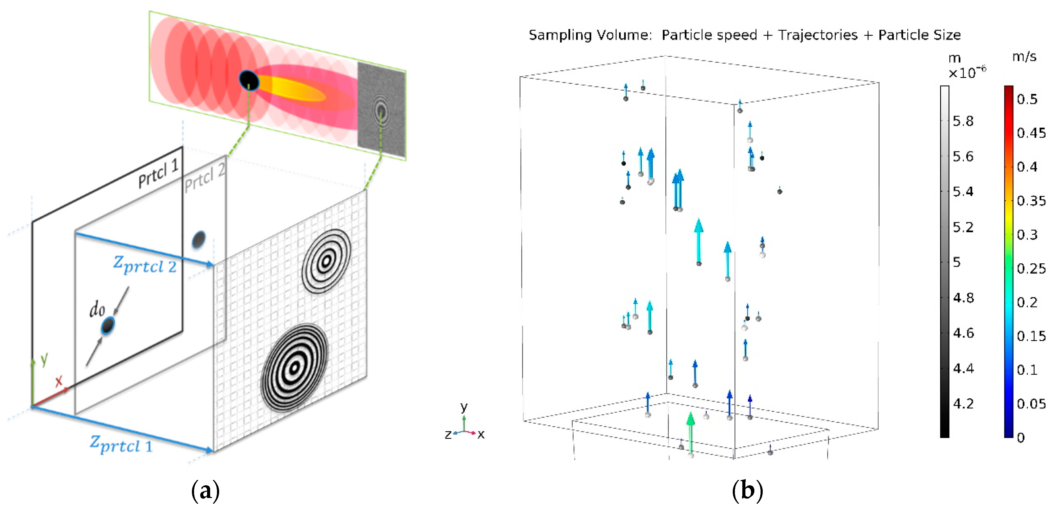
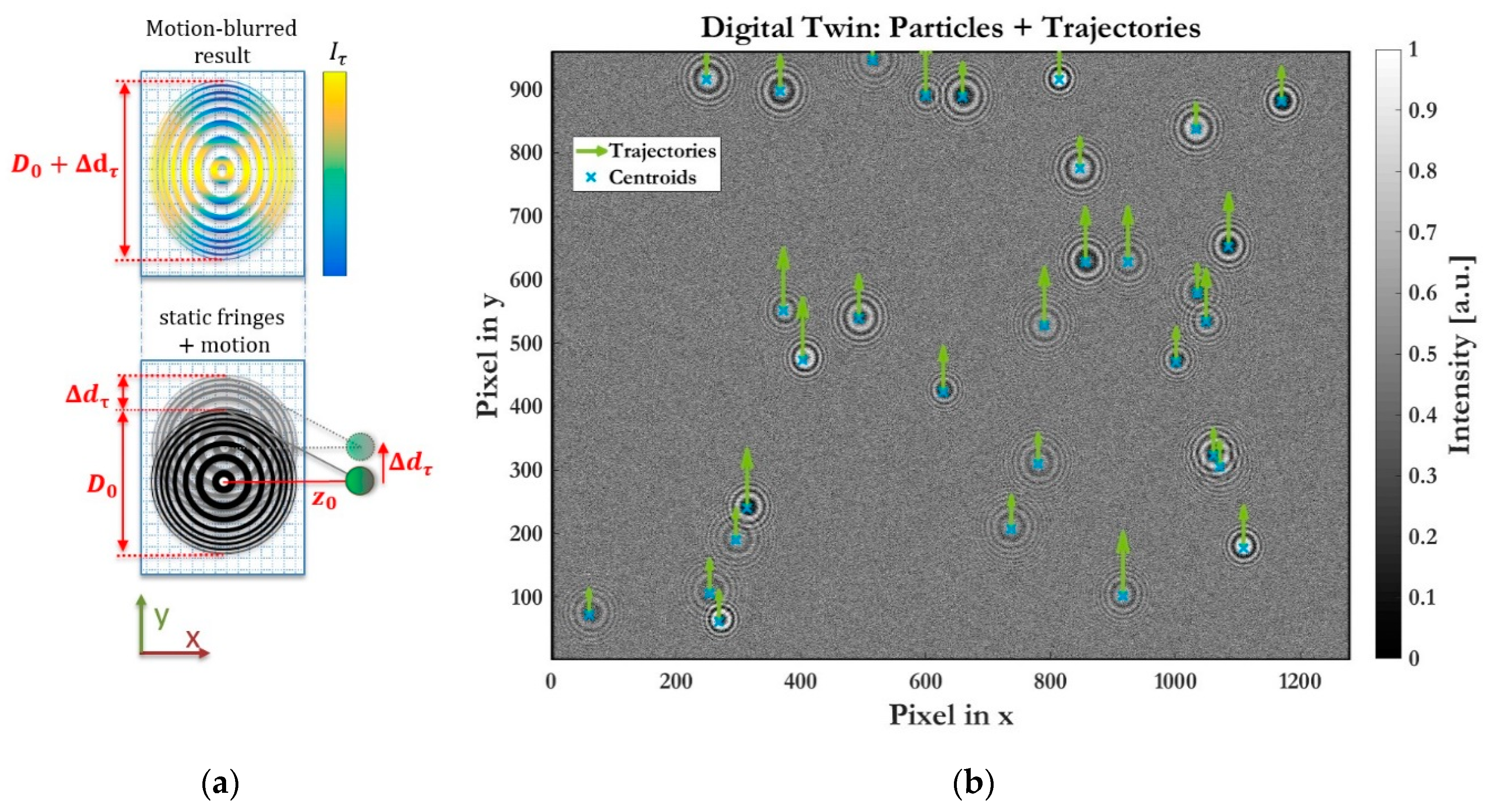
2.1. In-Line Holography Model

The aerosol particle model is based on the Angular Spectrum Method (ASM) [3] where each particle is considered a single point-like object, illuminated by a reference plane wave (see Figure 1a). The incident plane wave at the particle yields the so called complex amplitude Ψ p 0 ( x ,   y ) which is the initial condition at z p r t c l = 0 for calculating the field distribution. From that initial point, the diffracted field Ψ p ( x , y ; z p r t c l ) in a distance z p r t c l is obtained by solving the Helmholtz equation using Fourier transform in the form:
Ψ p ( x , y ; z p r t c l ) = 1 4 π 2 Ψ p 0 ( k x ,   k y ) H ( k x , k y ; z p r t c l ) e j k 0 z p r t c l ( 1 k x 2 k 0 2 k y 2 k 0 2 ) e j ( k x x + k y y ) d k x d k y
Ψ p 0 ( k x , k y ) in Equation (1) denotes the Fourier transform of the complex amplitude (also called angular plane wave spectrum) which propagates along the z-direction according to the spatial frequency transfer function H ( k x , k y ; z p r t c l ) . In a distance z p r t c l from the particle, the reference wave Ψ 0 and the object wave of the particle Ψ p interfere by I d e t = | Ψ 0 + Ψ p | 2 and form the detection or hologram plane. As shown in the principle model scheme in Figure 1a the interference of a plane wave and a spherical wave yield circular fringe patterns, given that both waves are mutually coherent over the detection plane. This implies the use of coherent light source, such as lasers.
Particle counters as mentioned at the beginning are based on aerosol particles which may be considered spherical microparticles and described by a few parameters, the spatial coordinates {x, y, z} and the particle radius r. Similar to [4], independent object planes are introduced and inserted into Equation (1) to calculate the diffracted field of multiple particles pi. The total hologram intensity at the detection plane consists of the sum of the diffraction patterns of all single particles.
The recording of the detection plane is modelled using a basic transfer function of an imaging sensor, taking into account the most relevant parameters imager size, pixel pitch, fill factor and exposure time. Background noise, such as quantization noise or electronic noise, are considered by Additive White Gaussian Noise (AWGN).

2.2. Aerosol Particle Model

To provide a multi-physical sensor model and incorporate further system relevant parameters with respect to holographic particle counters, Computational Fluid Dynamics (CFD) simulation data is employed to simulate an arbitrary aerosol volume in front of the imager. The fluid simulation contributes particle size distribution, particle number concentration, particle velocities and trajectories as well as flow characteristics of the sampling volume.
By introducing these additional flow properties, particles are displaced during exposure and the above static holography model does not hold true any more. Due to displacement during the exposure time τ, recorded holograms I τ ( r , t ) are motion-blurred modifications of static fringe patterns I ( r , t ) , which can be described by a convolution with the motion vector v ( t ) based on [5]:
I τ ( r , t | v ( t ) ) = I ( r , t ) [ 1 v ( t ) v 0 ( τ ) cos 2 ( θ + ϕ ( t ) 2 ) ]
where the intensity I ( r , t ) is blurred, dependent on the instantaneous speed v ( t ) of the particle traveling at an angle ϕ ( t ) relative to the x-axis. Assuming a constant displacement Δ d τ = v ( t ) · τ , while disregarding the z-component and the intensity blurring for sake of simplicity, a motion-blurred fringe pattern as outline in Figure 2a exhibits a uniformly geometrical expansion by the traveled distance Δ d τ . However, as evident from the Point Spread Function (PSF) from equation Equation (1), the dilation D 0 + Δ d τ of the static fringe pattern correlates to the distance z 0 . Based on Fresnel Zone Plate (FZP) theory [6], fringes are expressed as n zones of constructive and destructive interferences with dependency on the illumination wavelength λ and the focal length z 0 . Motion-blurred fringe patterns may therefore be approximated as ellipses with eccentricity ε to provide a simple and dimensionless feature for quantification and assessment:
ε n = 1 1 u n 2               w i t h :               u n = 1 + Δ d τ 2 n λ z 0 Δ d τ

3. Results

Fringe patterns at the hologram plane originate from the particles’ spatial coordinates and numerical aperture (particle size). Whereas the spatial {x,y}-coordinates of the particles are directly projected to the xy-orientation of the hologram plane, the size of the fringe patterns is related to the distance z p r t c l of the particles from the detection plane along the illumination beam. A strong variation in distances leads to a wide range of fringe pattern expansions. Thus, finding a meaningful range of distances which yield fringe pattern sizes with sufficient pixel resolution to be determinable and not occupying too much of the detection plane is essential for high density particle detection. Figure 2b shows a simulated detector plane with particle sizes in the range of d p r t c l = 4 6 µm and particle distances in the range of z p r t c l = 6 10 mm.
The figure clearly reveals that the determination of particle number in an arbitrary sampling volume can be extracted in-situ, where the sampling volume may also be unknown. Given the volume is known, particle concentration can be obtained from that. The herein described range of particle sizes is typical for micro-sized droplets in standard CPCs. Simulation results yield good hologram intensities to be determined by common image processing means and, thus, promises a great potential as an alternative optical detection unit for high density particle counters. Furthermore, the motion-blurred fringe patterns contain information about speed of motions and trajectories in its eccentricity and orientation. The eccentricity ε, however, is strongly dependent on the distance z as can be seen in Equation (3). As with increasing distances the influence to the geometric translation decreases and the eccentricity is smaller. Slower particles as well as shorter exposure times logically result in less motion-blurring. Using reconstruction methods as in [3,4] enable analysis of particle size and shape to obtain particle size distribution. In general, all input parameters of the aerosol particle model may be deduced from the hologram plane.
For high density particle counting, coincidence of particles is a limiting factor in state of the art 1D detection methods. Despite the same inherently limitation of the holographic detection approach (with overlapping fringe patterns), the spatial distribution of particles allow a better separability and, therefore, higher counting rates. Overlaps do not primarily result from spatially closely situated particles in the xy-plane but more likely from being closer or farther to the detector plane than its adjacent particle. Hence, coinciding particles along the illumination beam yield the most influencing contribution to overlapping patterns which implicates to keep the Depth of Field (DOF) smaller than the extent in x or y direction. Differences in the pattern’s intensities originate from variations in particle size, coming from the diffraction determining term Ψ p 0 ( k x , k y ) in Equation (1).

4. Conclusions

The presented model aids the design of a holographic imaging unit in order to find optimized dimensions of the sampling volume, the distance to the imager, imaging optics and the imager itself. In combination with a fluid dynamics simulation the particle flow in an arbitrary sampling volume is simulated to evaluate the effects of particle displacement or different exposure times. A holographic imaging unit does not only enable detection of higher particle densities but also allows the determination of particle size distribution, particle number concentration or aerosol flow characteristics.

Acknowledgments

This work was performed within the Competence Centre ASSIC—Austrian Smart Systems Research Center, co-funded by the Austrian Federal Ministries of Transport, Innovation and Technology (BMVIT) and Digital and Economic Affairs (BMDW) and the Federal Provinces of Carinthia and Styria within the COMET—Competence Centers for Excellent Technologies Programme.

Conflicts of Interest

The authors declare no conflict of interest. The founding sponsors had no role in the design of the study; in the collection, analyses, or interpretation of data; in the writing of the manuscript, and in the decision to publish the results.

References

  1. Giechaskiel, B.; Maricq, M.; Ntziachristos, L.; Dardiotis, C.; Wang, X.; Axmann, H.; Bergmann, A.; Schindler, W. Review of motor vehicle particulate emissions sampling and measurement: From smoke and filter mass to particle number. J. Aerosol. Sci. 2014, 67, 48–86. [Google Scholar] [CrossRef]
  2. Brunnhofer, G.; Bergmann, A.; Kraft, M. Concept for a holographic particle counter. In Proceedings of the 2017 IEEE Photonics Conference (IPC), Orlando, FL, USA, 1–5 October 2017; pp. 581–582. [Google Scholar] [CrossRef]
  3. Poon, T.C.; Liu, J.P. Introduction to Modern Digital Holography; Cambridge University Press: Cambridge, UK, 2014; p. 223. [Google Scholar]
  4. Gire, J.; Denis, L.; Fournier, C.; Thiébaut, E.; Soulez, F.; Ducottet, C. Digital holography of particles: Benefits of the ’inverse problem’ approach. Meas. Sci. Technol. 2008, 19, 074005. [Google Scholar] [CrossRef]
  5. Dixon, L.; Cheong, F.C.; Grier, D.G. Holographic particle-streak velocimetry. Opt. Express 2011, 19, 4393–4398. [Google Scholar] [CrossRef] [PubMed]
  6. Center for X-ray Optics. Fresnel Zone Plate Theory, Generation, Tolerancing, Fabrication, and Applications. 2014. Available online: http://Zoneplate.Lbl.Gov/Theory (accessed on 19 June 2018).
Figure 1. Aerosol particle model of a Holographic Particle Counter: (a) Principle In-Line holographic model scheme based on angular spectrum method (b) Aerosol Particle Model.
Proceedings 02 00967 g001
Figure 2. Aerosol particle model result: (a) scheme of motion-blurring in y-direction (b) 4.8 × 3.6 × 4 mm sampling volume of arbitrary particle density, with particle’s centroids and trajectories (with enhanced scale).
Proceedings 02 00967 g002
Publisher’s Note: MDPI stays neutral with regard to jurisdictional claims in published maps and institutional affiliations.

