Proceeding Paper

Design, Simulation and Fabrication of A Novel MEMS Based Pulsometer †

Electrical and Computer Engineering, Western Michigan University, Kalamazoo, MI 49008, USA
*
Author to whom correspondence should be addressed.
Presented at the Eurosensors 2018 Conference, Graz, Austria, 9–12 September 2018.
Proceedings 2018, 2(13), 951; https://doi.org/10.3390/proceedings2130951
Published: 3 December 2018
(This article belongs to the Proceedings of EUROSENSORS 2018)

Abstract

:
A novel pulsometer was successfully developed using microelectromechanical systems (MEMS) based silicon-on-glass (SOG) technology for biomedical applications. The sensor was modelled and simulated in COMSOL Multiphysics® for pressures ranging from 0 to 40 mmHg. The capability of the fabricated pulsometer to detect movements in x and z-axis directions was investigated. The simulation results demonstrated displacement changes as high as of 98% and 36% in the x and z-axis directions, respectively for 40 mmHg, which correspond to typical radial blood pressure (rBP) on the wrist. In addition, an average capacitance change of 1 nF was experimentally obtained in the x-axis direction, from −5 V to 5 V. The response of the pulsometer is analyzed and presented in this paper.

1. Introduction

Pulsometers, which are capable of detecting both blood pressure and heart rate, have been used for monitoring human cardiovascular conditions [1]. Pulsometers are fabricated using microelectromechanical systems (MEMS) based silicon-on-glass (SOG) technology. Typically, pulsometers are based on bridge structures and, therefore, suffer from low sensitivity and narrow functionality, due to displacement only in one axial direction [2,3,4,5,6]. Also, these devices require precision etching time and rate, to maintain accurate etch depth, and often consists of four or more layers, thus making them relatively expensive. To mitigate the drawbacks of the current pulsometer design and fabrication methods, a cantilever based pulsometer with high sensitivity and multi-functionality is developed. A cantilever based structure is envisioned to provide better sensitivity due to displacement in both x and z-axis directions. In this study, the capability of a novel cantilever based pulsometer is investigated using multiphysics simulation and experimental methods.

2. Methodology

2.1. Design

A schematic of the pulsometer is shown in Figure 1. The pulsometer was designed in AutoCAD®, with an overall dimension of 2 × 2 × 0.6 mm, using a comb-electrode configuration. The pulsometer consists of a glass substrate, silicon wafer and contact metal pads. The device has a terminal electrode and ground electrode. The terminal electrode or cantilever structure consists of flexible beams (4 µm wide), proof mass (1.5 × 0.6 mm) and a set of movable comb electrodes. The set of fixed electrodes are located on the ground electrode. The comb-electrodes have 88 interdigitated fingers with electrode width and pitch of 10.1 µm and 18.0 µm, respectively.

2.2. Working Principle

The working principle of the pulsometer is based on detecting the capacitance change between the ground electrode and the terminal electrode. When a pressure is exerted on the pulsometer, the cantilever structure moves and, therefore, causes a dynamic capacitance change in the terminal electrode due to its displacement from the initial position in the x- or z-axis directions. The spring constant of the cantilever beams is mathematically calculated using Equation (1) [7].
k = E W H 3 4 L 3
where, E is the Young Modulus, W is the width, H is the thickness and L is the length of the cantilever structure. The deflection of the terminal electrode, which is dependent on the spring constant of the cantilever beam can be calculated using Equation (2).
Δ x = F l o a d + F s e l f w e i g h t k
where, Fself-weight is the self-weight of the terminal electrode and the Fload is the load force exerted on top of the terminal electrode. The load force exerted by the pulse pressure on the pulsometer can be calculated using Equation (3).
F l o a d = P p u l s e × A t e r m i n a l
where, Ppulse is the pulse pressure and Aterminal is the top surface area of the terminal electrode. Therefore, from Equations (2) and (3), it can be concluded that the pulse pressure is directly proportional to the deflection of the terminal electrode.

2.3. Fabrication

The glass substrate was initially etched using hydrofloric acid (HF) to obtain an air recess of 3 µm (Figure 2a). The silicon wafer was anodically bonded to the glass substrate at 300 °C using two electrodes with a potential difference of 1 kV (Figure 2b). The terminal and ground electrode was patterned using deep reactive-ion etching (DRIE), etching away the targeted silicon for final release of structure (Figure 2c). Aluminum (Al) contact pads were finally deposited on the silicon layer (Figure 2d).

3. Results and Discussion

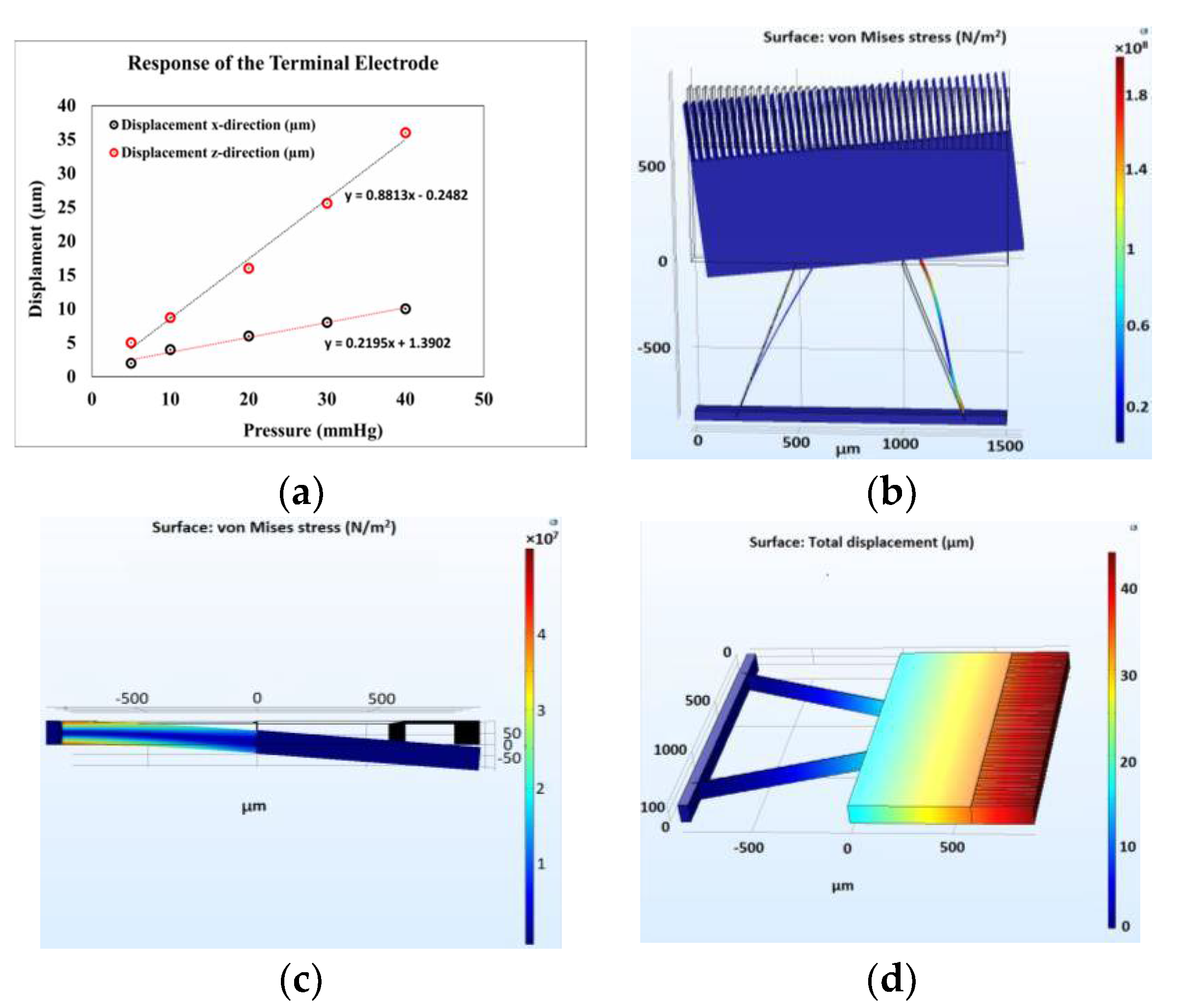
The response of the pulsometer was investigated by simulating the designed cantilever structure in COMSOL Multiphysics® simulation software using the solid mechanics module. The simulations were performed for an applied pressure range from 0 to 40 mmHg, which corresponds to the typical radial blood pressure (rBP) on the wrist [8]. As the pressure was increased from 0 to 40 mmHg, a maximum displacement of 9.8 µm and 36 µm was observed in the x and z-axis directions, respectively (Figure 3a). Based on the displacements, a capacitance change from 39 pF to 20 pF and 1950 pF was theoretically calculated in the x and z-axis directions, respectively. As an example, the displacements for an applied pressure of 5 mmHg in the x and z-axis directions are shown in Figure 3b,c, respectively. The results demonstrated a maximum displacement of 2 µm and 4.8 µm in the x and z-axis directions, respectively. In addition, the displacement distribution throughout the cantilever structure was also investigated by applying the typical rBP of 40 mmHg. It was observed that the maximum displacement of 36 µm, in the z-axis direction, was obtained at the comb-electrodes (Figure 3d).
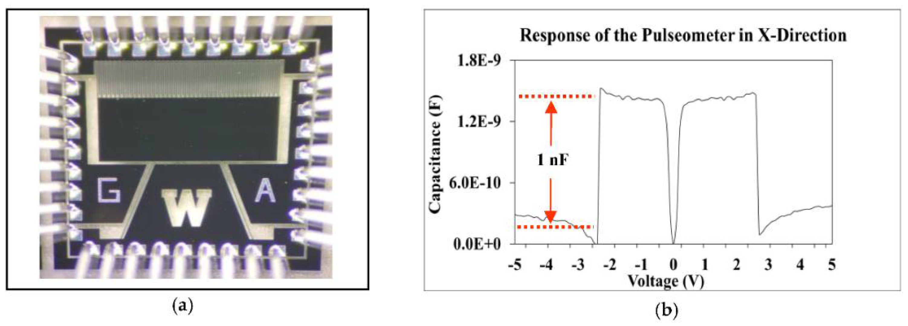
The fabricated pulsometer was connected to a SEMIPROBE™ PS4L-M6 probe station using a probe card (Figure 4a). The pulsometer was characterized in the x-axis direction by applying a voltage sweep from −5 to 5 V, at 1 KHz frequency, resulting in a capacitance change from 0.2 nF to 1.2 nF (Figure 4b), which corresponds to a capacitance change of 500%. The results obtained thus demonstrate the feasibility of employing the pulsometer for monitoring human cardiovascular conditions in biomedical applications.

4. Conclusions

In this work, a novel pulsometer was successfully modelled and simulated in COMSOL Multiphysics® for pressures ranging from 0 to 40 mmHg. In addition, the pulsometer was also fabricated using MEMS based SOG technology. Simulations performed using the solid mechanics module demonstrated displacement changes as high as of 98% and 36% in the x and z-axis directions, respectively for 40 mmHg, which correspond to typical radial blood pressure (rBP) on the wrist. Using the fabricated pulsometer, an average capacitance change of 1 nF was experimentally obtained in the x-axis direction, from −5 V to 5 V. Future work is in progress to enhance capability of the fabricated pulsometer by integrating it into a portable and real-time field deployable system for monitoring human cardiovascular conditions.

Acknowledgments

The authors would like to acknowledge access to Lurie Nanofabrication Facility (LNF) at University of Michigan and James Ricker for fabricating the devices.

References

  1. Inan, O.T.; Migeotte, P.F.; Park, K.S.; Etemadi, M.; Tavakolian, K.; Casanella, R.; Zanetti, J.M.; Tank, J.; Funtova, I.; Prisk, G.K.; et al. Ballistocardiography and Seismocardiography: A Review of Recent Advances. IEEE J. Biomed. Health Inform. 2015, 19, 1414–1427. [Google Scholar] [CrossRef] [PubMed]
  2. Ainsworth, B.; Cahalin, L.; Buman, M.; Ross, R. The Current State of Physical Activity Assessment Tools. Prog. Cardiovasc. Dis. 2015, 57, 387–395. [Google Scholar] [CrossRef] [PubMed]
  3. Koivisto, T.; Pänkäälä, M.; Hurnanen, T.; Vasankari, T.; Kiviniemi, T.; Saraste, A.; Airaksinen, J. Automatic Detection of Atrial Fibrillation using MEMS accelerometer. In Proceedings of the Computing in Cardiology Conference, Nice, France, 6–9 September 2015; pp. 829–832. [Google Scholar] [CrossRef]
  4. Atashbar, M.Z.; Bazuin, B.J.; Simpeh, M.; Krishnamurthy, S. 3-D finite-element simulation model of SAW palladium thin film hydrogen sensor. In Proceedings of the IEEE International Frequency Control Symposium and Exposition, Montreal, QC, Canada, 23–27 August 2004; pp. 549–553. [Google Scholar] [CrossRef]
  5. Gangadaran, S.; Varadan, V.V.; Varadan, V.K.; Jose, K.A.; Atashbar, M.Z. Love-wave-based Ice Sensor. In Proceedings of the Symposium Smart Materials Sensors 1999, Newport Beach, CA, USA, 20 July 1999; pp. 287–294. [Google Scholar] [CrossRef]
  6. Koivisto, T.; Pankaala, M.; Hurnanen, T.; Vasankari, T.; Kiviniemi, T.; Saraste, A.; Airaksinen, J. Automatic Detection of Atrial Fibrillation using MEMS accelerometer. In Proceedings of the Computing in Cardiology Conference (CinC), Nice, France, 6–9 September 2015; pp. 829–832. [Google Scholar] [CrossRef]
  7. Saha, S.C.; Hanke, U.; Jensen, G.U.; Saether, T. Modeling of Spring Constant and Pull-down Voltage of Non uniform RF MEMS Cantilever. In Proceedings of the IEEE International Behavioral Modeling and Simulation Workshop, San Jose, CA, USA, 14–15 September 2006; pp. 56–60. [Google Scholar] [CrossRef]
  8. Parati, G.; Stergiou, G.; O’brien, E.; Asmar, R.; Beilin, L.; Bilo, G.; Clement, D.; De La Sierra, A.; De Leeuw, P.; Dolan, E.; et al. European Society of Hypertension practice guidelines for ambulatory blood pressure monitoring. J. Hypertens. 2014, 32, 1359–1366. [Google Scholar] [CrossRef] [PubMed]
Figure 1. Schematic of the pulsometer: (a) top view and (b) side view.
Proceedings 02 00951 g001
Figure 2. (a) Etching glass to form recess, (b) anodic bonding of the glass substrate and silicon wafer, (c) DRIE pattern process and (d) deposition of metal contact pads.
Proceedings 02 00951 g002
Figure 3. Displacement of the cantilever structure: (a) in x and z-axis directions for varying pressure (0–40 mmHg), (b) in x-axis direction for 5 mmHg pressure, (c) in z-axis direction for 5 mmHg pressure, and (d) displacement distribution in z-axis direction for 40 mmHg pressure.
Proceedings 02 00951 g003
Figure 4. (a) Fabricated pulsometer connected to probe card and (b) capacitive response of the pulsometer from −5 V to 5 V.
Proceedings 02 00951 g004
Publisher’s Note: MDPI stays neutral with regard to jurisdictional claims in published maps and institutional affiliations.