1. Introduction
Passive LC sensors can be obtained by connecting a capacitive sensor to a coil, thus forming a resonant LC circuit where the measurement information is related to the resonant frequency and the quality factor of the LC circuit. By magnetically coupling the coil connected to the sensor to an external interrogation coil, contactless readout of the LC-sensor can be achieved [
1]. This configuration has recently gained particular interest in several fields such as industrial, chemical or biomedical applications. The lack of wired connection to the sensor is attractive in applications where cabled solutions are difficult or unpractical, such as measurement in sealed environments or inside animal/human bodies [
1,
2]. Additionally, these applications can take advantage on the absence of on-board power supply, allowing in principle for unattended unlimited operation. In-field measurement conditions are typically characterized by uncontrolled distance between the readout and the sensor coils, thus requiring interrogation techniques that desirably are independent of the distance between the coils. Approaches theoretically independent of the distance have been proposed both in the time-domain [
3,
4] and in the frequency-domain [
2]. In the latter case, measuring the real part of the impedance at the readout coil allows to obtain the resonant frequency and the quality factor of the LC sensor [
5,
6]. The present work investigates on the limitations of such technique when considering unavoidable parasitic capacitances in parallel to the readout coil due to the connected electronics and cables. By means of numerical simulations and experimental tests, it has been demonstrated that the parasitic capacitances introduce dependence on the distance. As a solution, a circuit is proposed to compensate for this unwanted effect.
2. Operating Principle
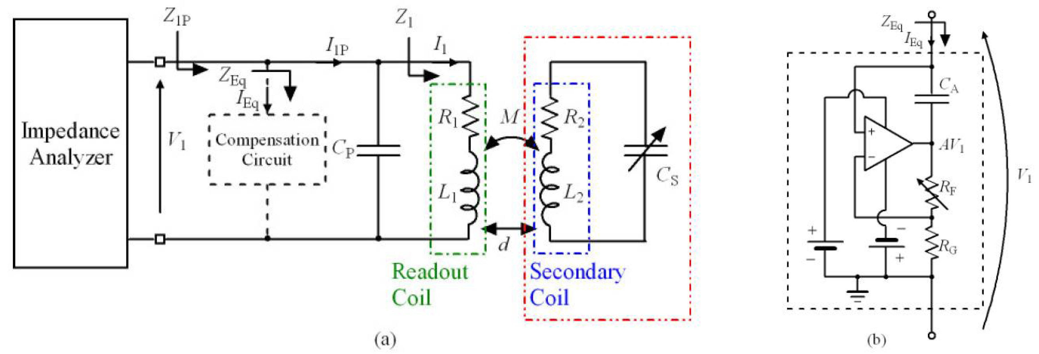
Figure 1a shows the schematic diagram of the proposed contactless readout system for capacitive sensors. It is composed of the interrogation unit made up by an impedance analyzer and the readout coil represented by inductance
L1 and series resistance
R1. The capacitance
CP models the parasitic elements coming from the windings of the coil, cables, and any electronic circuits connected in parallel to the readout coil. The readout coil is magnetically coupled to the secondary coil represented by inductance
L2 and series resistance
R2. The magnetic coupling is described through the coupling factor
k = ±
M/(
L1
L2)
1/2, where the mutual inductance
M is a parameter dependent on the interrogation distance
d between the two coils, their geometries and orientation. The secondary coil and the connected capacitive sensor
CS form a resonant LC circuit with resonant frequency
fS and quality factor
QS given by:
In particular, when
CP = 0 and without the compensation circuit, the sensor parameters
fS and
QS can in principle be measured by considering the real part Re{
Z1} of the equivalent impedance
Z1 =
V1/
I1 through the readout coil, which results:
From (2) it can be seen that
k acts only as a scaling factor and both
fS and
QS can be derived considering the frequency
fm of the maximum of Re{
Z1} and the Full Width at Half Maximum (FWHM) bandwidth Δ
fm trough the following relations [
2]:
From (3) it can be observed that for sufficiently large values of
QS, it results
fm ≈
fS, obtaining a relative deviation (
fm –
fS))/
fS < 100 ppm for
QS > 50. When
CP ≠ 0 again, and without considering the compensation circuit, the real part of the impedance
Z1
P =
V1/
I1
P =
Z1//
ZCP has the following more complex expression:
From (3) and (4) it can be seen that now k does not act only as a scaling factor and without knowing its value in advance, it is not possible to extract fS and QS.
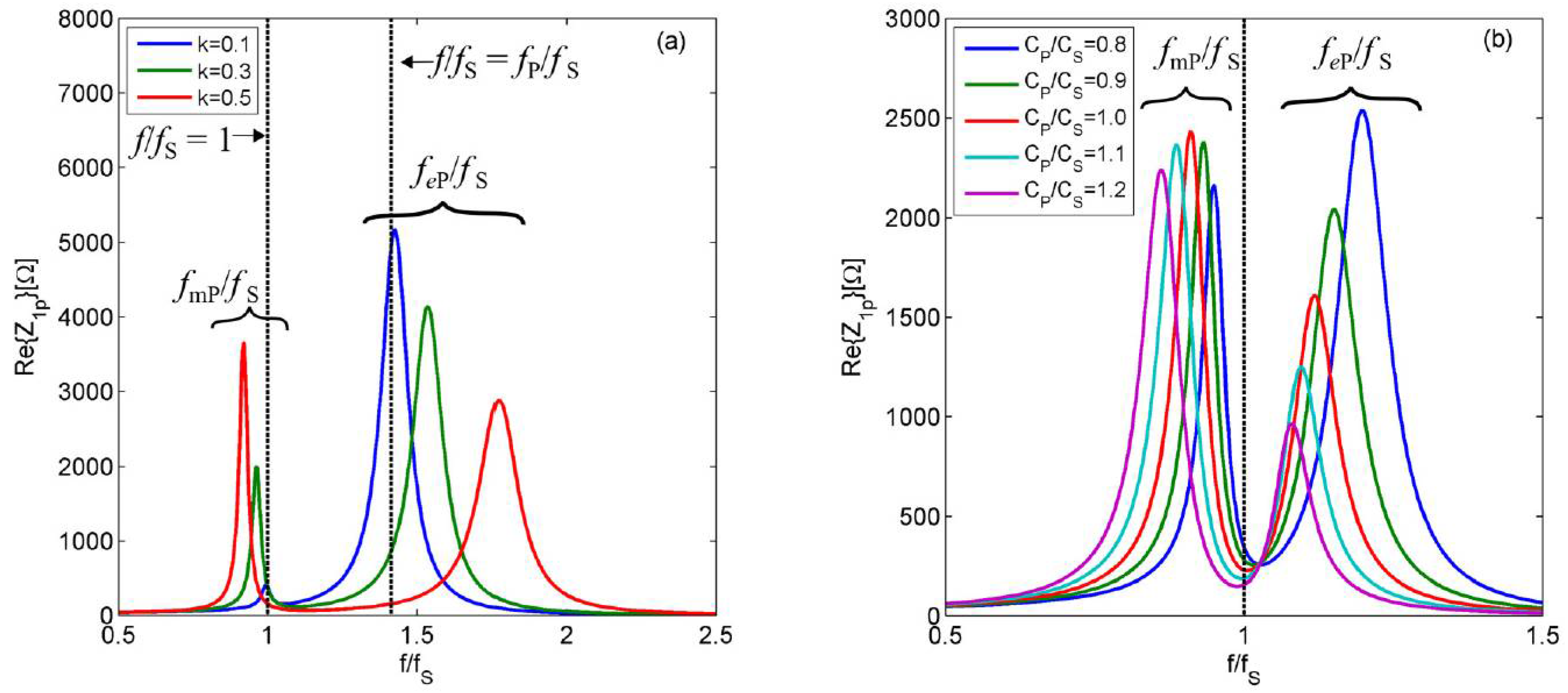
An analysis of the effects of
k and
CP on Re{
Z1
P} has been performed numerically.
Figure 2a shows Re{
Z1
P} against
f/
fS, i.e., the frequency normalized to
fS, for three different values of
k when
CP/
CS = 0.5. The two vertical dotted lines are for
f/
fs = 1, i.e., corresponding to the resonant frequency of the LC sensor, and for
f/
fs =
fP/
fS, i.e., corresponding to the secondary resonant frequency
fP = 1/(2π√(
L1
CP)) due to
L1 resonating with
CP. When
CP ≠ 0, two peaks are present in Re{
Z1
P}. Denoting with
fmP/
fS the position of the maxima close to
f/
fS = 1 and with
feP/
fS those close to
fP/
fS, it can be observed that for decreasing values of
k,
fmP/
fS moves towards 1 and the associated peak value decreases, while
feP/
fS tends to
fP/
fS and the associated peak value increases, proving the distance-dependent behavior. For
k = 0 there is no coupling between the readout coil and the sensor coil, and in that case, the height of the peak close to
f/
fS = 1 vanishes and only the peak at
fP/
fS can be measured.
Figure 2b shows the effect of different values of
CP/
CS at fixed
k = 0.2. From the results, it can be noticed that for increasing
CP/
CS, the ratio
fmP/
fS moves towards values lower than 1, while the ratio
feP/
fS tends to 1.
To avoid the dependence of
fmP on
CP and hence on the distance, the proposed compensation circuit of
Figure 1b is connected in parallel to the readout coil. The circuit operates as a Negative Impedance Converter (NIC) providing the equivalent impedance
ZEq =
V1/
IEq = 1/(
j2
πf(-
CC)), where the negative capacitance −
CC = −
CARF/RG can be tuned through
RF to compensate and possibly cancel
CP.
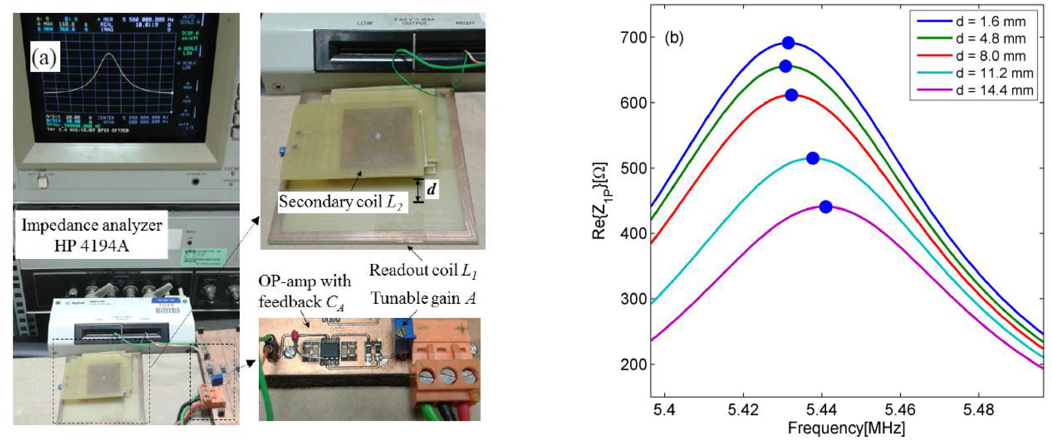
3. Circuit Prototype and Experimental Results
The compensation circuit of
Figure 1b has been built by using a high-bandwidth operational amplifier (AD8045).
Figure 3a shows the prototype and the experimental setup adopted to validate the proposed technique. The measured equivalent parameters for the readout and sensor coils are
L1 = 8.17 µH and
R1 = 3.12 Ω, and
L2 = 8.50 µH and
R2 = 3.20 Ω respectively. For the capacitive sensor, a capacitance
CS = 99 pF has been adopted which from (1) gives for the LC resonant circuit
fS = 5.48 MHz and
QS = 91.5.
To validate the numerical analysis of
Section 2,
Figure 3b shows the measured Re{
Z1
P} around
fS at five different distances when a total parasitic capacitance of
CP = 47 pF is present. It can be observed that, in agreement with the predictions of
Figure 2a, the frequency of the maximum of Re{
Z1
P} shifts towards higher frequencies for increasing distances, i.e., for decreasing values of
k.
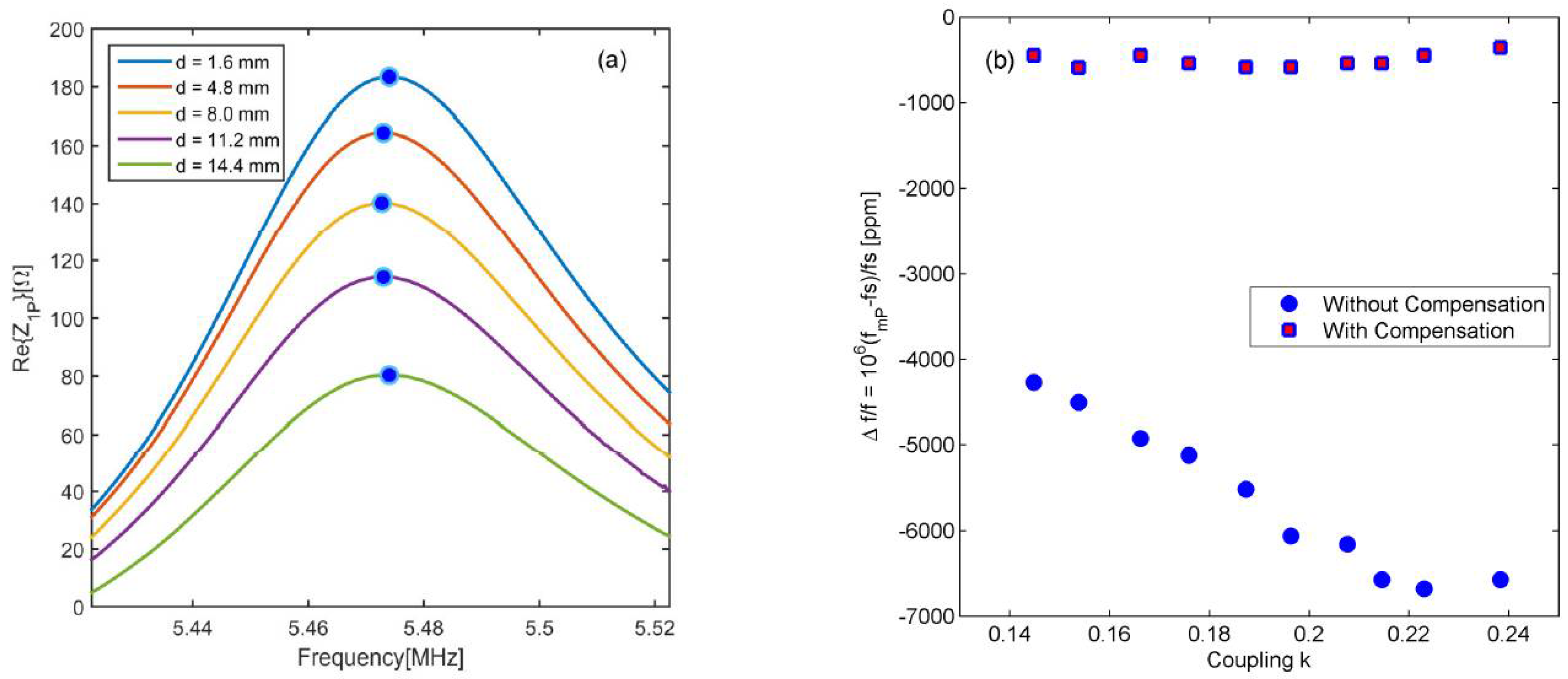
Figure 4a shows the results of the same test with the compensation circuit tuned for the cancellation of
CP activated.
Figure 4b compares the cases of
Figure 3b and
Figure 4a, showing the relative frequency deviation Δ
f/
f = 10
6(
fmP −
fS)/
fS as a function of the estimated coupling factor
k. With the compensation circuit connected, a maximum relative deviation Δ
f/
f less than 200 ppm is achieved.


