Abstract
In this study, a microplasma discharge device (MDD) was modelled and simulated for sterilization applications. The MDD was modelled with copper and dielectric based electrodes on flexible polyethylene terephthalate substrate. COMSOL Multiphysics® simulation performed on the MDD model demonstrated varying electron density and electric field distribution for AC terminal voltages ranging from 500 V to 8000 V. A variation of 14% and 54% was also observed for electron density and mobility, respectively when the temperature was increased from 240 K to 360 K, at constant pressure of 1 atm. In addition, a variation of 90% and 78% was observed for electron density and mobility, respectively when the pressure was increased from 0.3 atm to 1.3 atm, at constant room temperature of 295 K. The response of the MDD is analysed and presented in this paper.
1. Introduction
Sterilization is the process of neutralizing microorganisms on a surface. Traditional sterilization methods typically employ special chambers and materials. These methods are often bulky, nonportable and leaves hazardous waste [1,2]. Microplasma discharge devices (MDD), which are based on non-thermal or cold plasmas, have been receiving growing interest for various applications in the food, biomedical, environmental and health care industries [1,2,3]. MDDs have been primarily used for surface modifications, ozone synthesis and bacterial inactivation [1,2]. The performance of MDDs are dependent on a stable and uniform microplasma discharge. To maintain the uniform distribution of microplasma discharge, MDDs are often operated in specialized chambers which employ gases such as argon, neon, helium, xenon and nitrogen [1]. Further, MDDs are operated in controlled environments under stable operating conditions (temperature, pressure and humidity), thus making the systems complex, bulky, non-portable and expensive [1,2]. To alleviate these problems, research has shown the development of miniaturized, portable and cost-effective MDDs that operate in atmospheric air [1,2]. However, by operating MDDs in atmospheric air, the devices are exposed to varying ambient conditions including dynamic temperature and pressure changes. These changes influence the electron density (ED) and electron mobility (EM) across the MDDs, which could result in unstable and non-uniform distribution of microplasma discharge [4]. In this study, the effects of varying voltage, and ambient conditions such as temperature and pressure across the MDD electrode gap is investigated using finite element analysis (FEA).
2. Design and Theory
The electrode configuration for the MDD, with an overall dimension of 16 mm × 5 mm, was designed in AutoCAD® (Figure 1). The operating principle of the microplasma discharge for this study is based on dielectric barrier discharge (DBD) [1]. The MDD consists of two copper electrodes, with dielectric tips (relative permittivity of 10) and an electrode gap distance of 0.5 mm. The microplasma is formed in between the dielectric tips of the electrodes where one of the electrodes is grounded (ground electrode) and a sinusoidal voltage is applied to the other electrode (terminal electrode). The applied voltage should be high enough to cause ionization of the discharge media. The free electrons in the discharge gap accelerates and acquires higher potential which leads to a cascading effect increasing the number of free electrons. The free electrons and the ionized charge species move across the discharge gap to the opposite electrode potential [1]. This process of charge accumulation is temporary and when the electric field potential is reversed, the process reverses in the opposite direction and repeats as long as the sinusoidal voltage is applied.
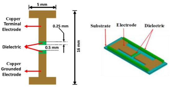
Figure 1.
Microplasma discharge device electrode configuration.
3. Numerical Simulation
The operating principle of microplasma is based on Paschen’s Law which states that the breakdown voltage (VB) of an MDD is a function of the ambient pressure (p) (Pa) and electrode gap distance (d) [5]. The relation between VB and p is given by Equation (1) [5].
where, A is the ionization saturation constant, B is the excitation & ionization energy constant, and γse is the secondary electron coefficient. Using Paschen’s Law, a breakdown voltage of 1500 V was calculated for an optimum electrode gap distance of 0.5 mm (Figure 2).
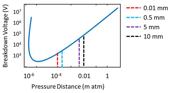
Figure 2.
Paschen’s curve at varying electrode gap distances of 0.01 mm, 0.5 mm, 5 mm, 10 mm.
In the FEA simulation, performed in COMSOL Multiphysics® the constituent equations from the Drift Diffusion Model (DDM) was used for determining the ED across the ground and terminal electrodes of the designed MDDs, during microplasma discharge [6]. The ED is mathematically calculated using Equation (2) [6].
where,
and, ne denotes the ED (1/m3), Re is the electron rate expression (1/(m3·s)), µe is the EM which is either a scalar or tensor (m2/(V·s)), E is the electric field (V/m), De is the electron diffusivity (m2/s), and −(µe·E)ne and −De·∇ne represents the effect of electric field on electron migration and electron diffusion between high to low ED, respectively. The effect of ED and the electric field, of varying input voltages across the discharge gap between the two electrodes was simulated and investigated.
Using the classical kinetic theory, EM is dependent on the change in ambient temperature (Ta), and is mathematically given by Equation (4) [7].
where, N is the gas density, σmt is the electron-atom momentum transfer scattering cross section, m and e are the electron mass and charge respectively, kB is the Boltzmann’s constant. Also, from the ideal gas law [8], since p is dependent on Ta and N, it can be inferred that a change in ambient conditions (pressure and/or temperature) will affect the EM and ED. Therefore, the effect of varying Ta (240 K to 360 K) at a constant p (1 atm) was investigated. Similarly, the effect of varying p (0.3 atm to 1.1 atm) at constant Ta (295 K) was also studied.
4. Results
The MDD model was simulated in COMSOL Multiphysics® using the plasma module in argon environment. Figure 3 shows the behavior of the microplasma before breakdown voltage, at breakdown voltage and at stable high voltages. At 500 V, the Ar molecules were not ionized. Even though the molecules attained higher electron energy, the electric potential was not sufficient for breakdown to occur. At 1500 V terminal potential difference, Ar molecules were ionized, becoming Ar+ and e−. The electrons migrated towards the ground electrode and Ar ions migrated towards the terminal electrode, thereby creating a microplasma discharge. As the voltage was further increased beyond the breakdown voltage to 4000 V, more Ar molecules were ionized into Ar+. The ED thus increased and migrated towards the ground electrode, creating a more stable microplasma discharge. Further, as the voltage was increased to 8000 V, there was no significant increase in the ED.
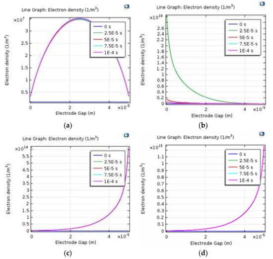
Figure 3.
Electron density across the surface of the terminal and ground electrodes for increasing terminal voltage: (a) 500 V (b) 1500 V (c) 4000 V (d) 8000 V.
Figure 4 shows the effect of varying voltages on the electric field distribution across the electrode gap of the MDD. It was observed that the electric field was concentrated on the terminal electrode when the voltage was low (500 V) and since there was no plasma discharge at this point the total charge distribution across the electrode was neutral. As the voltage was increased to the breakdown voltage (1500 V), the rate of ionization increased, allowing more electrons to migrate towards the grounded electrode. As the applied voltage was further increased to 4000 V and 8000 V, the electric field was much higher at the ground electrode when compared to the terminal electrode.
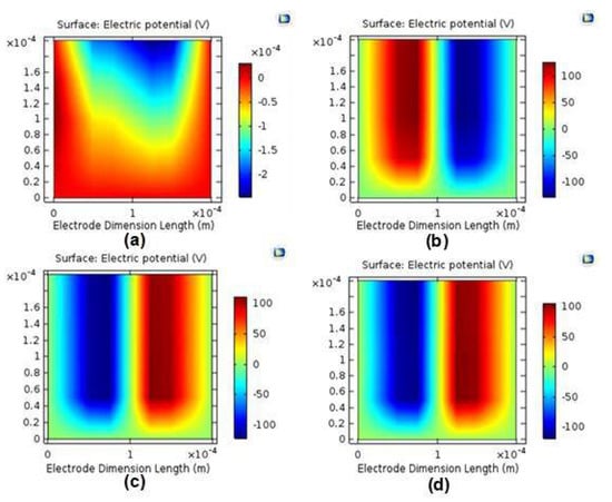
Figure 4.
Electron field across the surface of the terminal and ground electrodes for increasing terminal voltage: (a) 500 V (b) 1500 V (c) 4000 V (d) 8000 V.
In Figure 5, the effect of Ta on ED and EM is shown. It was observed that the ED and EM varied from 1.57 × 10¹³ m−3 to 1.35 × 10¹³ m−3 and 0.13 [m2/(V·s)] to 0.20 [m2/(V·s)], respectively, as Ta increased from 240 K to 360 K, in steps of 20 K and at constant p (1 atm). This corresponds to a 14% and 54% change in ED and EM, respectively, for the Ta ranging from 240 K to 360 K. In Figure 6, the effect of p on ED and EM is shown. As the p increased from 0.3 atm to 1.3 atm, at constant Ta (295 K), it was observed that the ED increased from 0.82 × 10¹³ m−3 to 1.56 × 10¹³ m−3 resulting in a 90% variation. The EM decreased from 0.54 [m2/(V·s)] to 0.12 [m2/(V·s)] resulting in a 78% variation for the p ranging from 0.3 atm to 1.3 atm. From the results, it was demonstrated that the ED and EM were inversely proportional to each other for varying Ta and p.
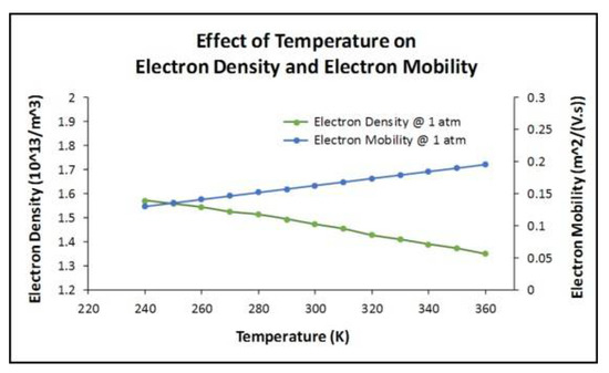
Figure 5.
The effect of temperature on electron density and electron mobility at constant pressure of 1 atm.
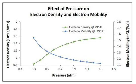
Figure 6.
The effect of pressure on electron density and electron mobility at constant temperature of 295 K.
5. Conclusions
In this work, an MDD was successfully modelled and simulated using FEA in COMSOL Multiphysics®. The MDD was modelled with copper and dielectric based electrodes on flexible polyethylene terephthalate substrate. Initially, simulations were performed on the MDD model to investigate the ED and electric field distribution for AC terminal voltages ranging from 500 V to 8000 V. Then, the effect of varying Ta and p on ED and EM of the MDD was studied. A variation of 14% and 54% was observed for ED and EM, respectively when Ta was increased from 240 K to 360 K at constant p of 1 atm. A 90% and 78% change was observed for the ED and EM, respectively when the p was increased from 0.3 atm to 1.3 atm at constant Ta of 295 K. For bacterial sterilization, the charged species from the MDD is an important component for effective sterilization [9]. Therefore, a change in ED and EM will affect the sterilizing efficacy of the MDD. Further research includes the fabrication of MDDs for to investigate the effect of varying voltages, Ta and p for the sterilization of gram-negative bacteria such as Escherichia coli and Pseudomonas aeruginosa.
References
- Becker, K.H.; Schoenbach, K.H.; Eden, J.G. Microplasmas and applications. J. Phys. D Appl. Phys. 2006, 39, 55–70. [Google Scholar] [CrossRef]
- Becker, K. Microplasmas, a platform technology for a plethora of plasma applications. Eur. Phys. J. Spec. Top. 2017, 226, 2853–2858. [Google Scholar] [CrossRef][Green Version]
- Bose, A.K.; Maddipatla, D.; Narakathu, B.B.; Turkani, V.S.; Bazuin, B.J.; Atashbar, M.Z. Flexible microplasma discharge device for the detection of biochemical. In Proceedings of the 17th International Meeting on Chemical Sensors—IMCS 2018, Vienna, Austria, 15–19 July 2018; pp. 419–420. [Google Scholar] [CrossRef]
- Stauss, S.; Muneoka, H.; Terashima, K. Review on plasmas in extraordinary media: Plasmas in cryogenic conditions and plasmas in supercritical fluids. Plasma Sources Sci. Technol. 2018, 27. [Google Scholar] [CrossRef]
- Berzak, L.F.; Dorfman, S.E.; Smith, S.P. Paschen’s Law in Air and Noble Gases; Lawrence Berkeley National Laboratory: Berkeley, CA, USA, 2006. [Google Scholar]
- COMSOL: Application Gallery. Available online: https://www.comsol.com/model/dielectric-barrier-discharge (accessed on 7 April 2018).
- Borghesani, A.F.; Lamp, P. Electron mobility in dense argon gas at several temperatures. Trans. Dielectr. Electr. Insul. 2003, 10, 977–984. [Google Scholar] [CrossRef]
- Kautz, C.H.; Heron, P.R.; Loverude, M.E.; McDermott, L.C. Student understanding of the ideal gas law, Part I: A macroscopic perspective. Am. J. Phys. 2005, 73, 1055–1063. [Google Scholar] [CrossRef]
- Rossi, F.; Kylian, O.; Rauscher, H.; Hasiwa, M.; Gilliland, D. Low pressure plasma discharges for the sterilization and decontamination of surfaces. New J. Phys. 2009, 11, 115017. [Google Scholar] [CrossRef]
Publisher’s Note: MDPI stays neutral with regard to jurisdictional claims in published maps and institutional affiliations. |
© 2018 by the authors. Licensee MDPI, Basel, Switzerland. This article is an open access article distributed under the terms and conditions of the Creative Commons Attribution (CC BY) license (https://creativecommons.org/licenses/by/4.0/).