Abstract
This work reports for the first-time integration of continuous microfluidic channels to the paper-based electro-osmotic pumps (EOPs) with liquid bridges. In addition, 0.2 μm pore sized cellulose acetate (CA) membrane filter is used to eliminate pressure-driven flow instead of filter paper which is common in paper microfluidics and has an average pore size of 10 μm. A factor of 57 increase in hydraulic resistance is achieved with the new paper. Fabrication of the pumps and microfluidic channels using paper, wax, adhesive film and PMMA plates is explained. Volumetric flow rate of 19 nL/min is achieved in the microfluidic system with 61 V/cm electrical field magnitude applied to DI water. The capability of the integrated system is shown with precise liquid motion in a Y-shaped microfluidic channel integrated with two EOPs.
1. Introduction
Most of the microfluidic applications use regular continuous microfluidic channels to mix, amplify, separate and analyze DNA, protein and cells. Electro-osmotic pumping can offer promising liquid handling solutions to these applications [1]. However, pressure driven back flow and bubble formation at the electrodes limit their usage. To eliminate these limitations, porous plug EOP’s [2,3] and liquid bridge connections [4] were suggested before. Similar to these works, we introduced paper based EOPs recently, which use paper as porous medium [5]. Paper-based EOPs can offer simple, compact and lightweight pumping solutions to the microfluidic systems mentioned above if their porous channels can be integrated to continuous microfluidic channels. In this work, we report this integration effort for the first time. A simple example of the envisioned integrated system is shown in Figure 1.
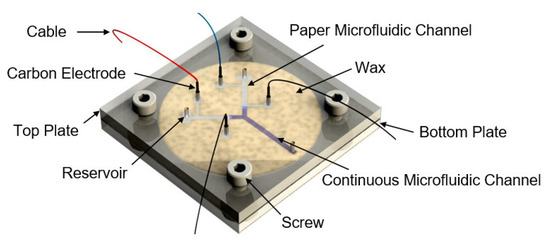
Figure 1.
Demonstration of the microfluidic system with paper based electro-osmotic pumps.
In addition, 0.2 μm pore sized cellulose acetate (CA) membrane filter is used to further eliminate pressure-driven flow instead of filter paper that is commonly used in paper microfluidics which has an average pore size of 10 μm.
2. Design and Optimization
We optimized design parameters of paper based EOPs with liquid bridges in our previous work [5]. We still had significant pressure-driven flows with the typical Whatman filter paper (average 10 μm pore size) used in that work [6,7]. To solve this problem, we used cellulose acetate membrane filter with average pore size of 0.2 μm in this work. We characterized hydraulic resistances of both papers. Red-dyed water at different heights were applied to wetted papers and their motions were recorded. Experimental results are shown in Figure 2. Hydraulic resistance improved 57 times with membrane filter.
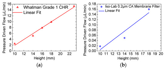
Figure 2.
Pressure driven flow results of the Whatman Grade 1 CHR filter paper (a) and 0.2 μm cellulose acetate (CA) membrane filter (b) as the applied water height changes.
3. Fabrication
EOPs are fabricated by patterning wax on membrane filter using a thermal nozzle attached to a three-axis CNC router as in our previous work [5]. Then, this paper is attached to the bottom PMMA plate using double-sided tape. Continuous microfluidic channels are formed on top PMMA plate by the engraving feature of the laser cutter. Similarly, reservoir and electrode holes are cut through on this plate by the same laser cutter. After surfaces are wetted with DI water, top plate is placed upside down on the bottom plate and they are pressed together. Procedure is demonstrated in Figure 3.
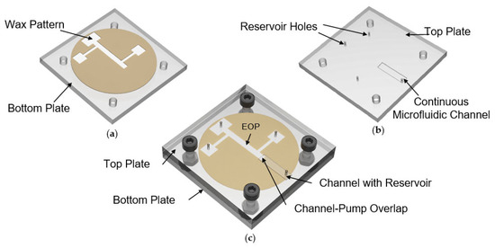
Figure 3.
Fabrication of the system: (a) Wax pattern is extruded on paper. Paper is held on the bottom plate; (b) A continuous microfluidic channel and reservoir holes are made on top plate using a laser cutter; (c) Top plate is placed upside down on bottom plate and mechanically secured after wetting plate surfaces.
Fabricated device using Iso-Lab 0.2 μm cellulose acetate membrane filter along with a continuous microfluidic channel is shown in Figure 4.
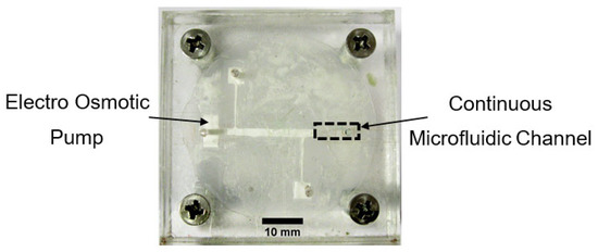
Figure 4.
Photograph of the fabricated device.
4. Results
Water pumping in the continuous microfluidic channel generated by the electro osmotic pump on the membrane filter is shown in Figure 5. DI water is pumped into the continuous microfluidic channel of 120 μm height and 2 mm width against an 8 mm water level height. At time zero, an electric field magnitude of 61 V/cm is applied to the electrodes of the pump. Liquid motion in the continuous channel is demonstrated in this figure with the photos taken at equal time intervals of 300 s. This indicates an average velocity of 1.4 μm/s.
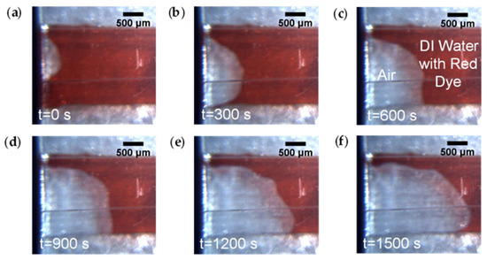
Figure 5.
Electroosmotic pumping on the continuous microfluidic channel using membrane filter. Photos are taken (a) at the beginning; (b) at 300 s; (c) at 600 s; (d) at 900 s; (e) at 1200 s; (f) at 1500 s.
Generated volumetric flow rates of EOPs with both types of papers under different electrical field magnitudes using DI water are shown in Figure 6. Results indicate 2.4 times higher volumetric flow rate using Iso-Lab 0.2 μm cellulose acetate membrane filter (17 nL/min) compared to Whatman Grade 1 CHR paper (7 nL/min) under 61 V/cm electric field magnitude.
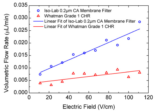
Figure 6.
Volumetric flow rates of the pumps made with Whatman paper and CA membrane filter with different electrical field magnitudes, measured inside their microfluidic channels.
A simple integrated system is realized by integrated two EOPs to a continuous Y-shaped microfluidic channel as shown in Figure 7. One EOP pumps yellow dyed DI water to the Y channel, while the other is off holding blue-dyed DI water. Passage of yellow-dyed water from the porous medium to the continuous microfluidic channel is visible in Figure 7 while blue-dyed water stayed stationary.
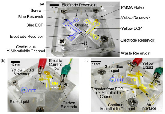
Figure 7.
(a) Demonstration of motion control of two different liquids with two integrated EOPs and a continuous Y-shaped microfluidic channel; (b) Yellow EOP is turned on while blue EOP is turned off; (c) Yellow liquid passes from porous EOP to continuous microfluidic channel while blue liquid is restrained.
Acknowledgments
This work is supported by Bogazici University Research Fund Grant Number 11664.
Conflicts of Interest
The authors declare no conflict of interest.
References
- Wang, X.; Cheng, C.; Wang, S.; Liu, S. Electroosmotic pumps and their applications in microfluidic systems. Microfluid Nanofluidics 2009, 6, 145–162. [Google Scholar] [CrossRef] [PubMed]
- Mutlu, S.; Yu, C.; Selvaganapathy, P.; Svec, F.; Mastrangelo, C.H.; Frechet, J.M.J. Micromachined porous polymer for bubble free electro-osmotic pump. In Proceedings of the Fifteenth IEEE International Conference on Micro Electro Mechanical Systems (Cat. No.02CH37266), Las Vegas, NV, USA, 24 January 2002; pp. 19–22. [Google Scholar] [CrossRef]
- Seibel, K.; Scholer, L.; Schafer, H.; Bohm, M. A programmable planar electroosmotic micropump for lab- on-a-chip applications. J. Micromech. Microeng. 2007, 18, 25008. [Google Scholar] [CrossRef]
- Mutlu, S.; Svec, F.; Mastrangelo, C.H.; Frechet, J.M.J.; Gianchandani, Y.B. Enhanced electro-osmotic pumping with liquid bridge and field effect flow rectification. In Proceedings of the 17th IEEE International Conference on Micro Electro Mechanical Systems. Maastricht MEMS 2004 Technical Digest, Maastricht, The Netherlands, 25–29 January 2004; pp. 850–853. [Google Scholar] [CrossRef]
- Celik, A.Y.; Kaya, K.; Mutlu, S. Paper based integrated microfluidic system using electro-osmotic pumps with liquid bridges. In Proceedings of the 2018 IEEE Micro Electro Mechanical Systems (MEMS), Belfast, UK, 21–25 January 2018; pp. 1225–1229. [Google Scholar] [CrossRef]
- Evans, E.; Gabriel, E.F.M.; Coltro, E.F.M.; Garcia, C.D. Rational selection of substrates to improve color intensity and uniformity on microfluidic paper-based analytical devices. Analyst 2014, 139, 2127–2132. [Google Scholar] [CrossRef]
- Carrilho, E.; Martinez, A.W.; Whitesides, G. M Understanding wax printing: A simple micropatterning process for paper-based microfluidics. Anal. Chem. 2009, 81, 7091–7095. [Google Scholar] [CrossRef] [PubMed]
Publisher’s Note: MDPI stays neutral with regard to jurisdictional claims in published maps and institutional affiliations. |
© 2018 by the authors. Licensee MDPI, Basel, Switzerland. This article is an open access article distributed under the terms and conditions of the Creative Commons Attribution (CC BY) license (https://creativecommons.org/licenses/by/4.0/).