Abstract
This paper presents a long-term stable thermoelectric micro gas sensor with ligand linked Pt nanoparticles as catalyst. The sensor design gives an excellent homogeneous temperature distribution over the catalytic layer, an important factor for long-term stability. The sensor consumes very low power, 18 mW at 100 °C heater temperature. Another thermoresistive sensor is also fabricated with same material for comparative analysis. The thermoelectric sensor gives better temperature homogeneity and consumes 23% less power than thermoresistive sensor for same average temperature on the membrane. The sensor shows linear characteristics with temperature change and has significantly high Seebeck coefficient of 6.5 mV/K. The output of the sensor remains completely constant under 15,000 ppm continuous H2 gas flow for 24 h. No degradation of sensor signal for 24 h indicates no deactivation of catalytic layer over the time. The sensor is tested with 3 different amount of catalyst at 2 different operating temperatures under 6000 ppm and 15,000 ppm continuous H2 gas flow for 4 h. Sensor output is completely stable for 3 different amount of catalyst.
1. Introduction
Power consumption of a micro gas sensor is an important issue for battery-powered operation [1,2]. Conversely, a homogeneous temperature distribution over the sensing element is needed for long-term stable operation [3]. This is because higher temperature leads to sintering of nanoparticles and lower temperature causes water accumulation on catalytic layer [1]. As a result, the catalyst deactivates and sensitivity decreases. This factor limits long-term stable operation of the sensor [1]. Therefore not only low power consumption but also homogeneous temperature distribution over catalytic layer is an important factor for high sensitivity and stable operation of the sensor. Thermoresistive H2 gas sensor presented by E. Lee et al. consumes 55.68 mW power at 115 °C operating temperature [4]. Although some conventional thermoresistive gas sensors explained in current research consume comparatively low power, it does not provide homogeneous temperature profile [5]. The newly designed thermoelectric micro gas sensor with circular membrane and thermopile gives very homogeneous temperature distribution over the catalytic layer and consumes quite low power, 18 mW at 100 °C heater temperature. This homogeneous temperature field increases stability and sensor shows constant output for long-term continuous operation.
2. Material and Methods
2.1. Sensor Fabrication and Catalyst
The sensor has two SiN membranes and high Seebeck coefficient thermopile, 6.5 mV/K. Figure 1a shows a schematic cross-section of the thermoelectric sensor. Thermopiles of polysilicon-WTi and a WTi micro heater are sandwiched in 600 nm high-temperature stable LPCVD SiN membrane. TiN and TEOS are diffusion barrier between polysilicon and WTi and etch stop for TiN respectively. 40 µm high SU8 cylinder is a catalyst reservoir and Au is used for bond pads. Membranes are released by deep reactive ion etching (DRIE). Pt nanoparticles are stabilized by ligands, p-Phenylenediamine (PDA). The nanoparticles are linked with ligands directly on the membrane with two distinct micro dispensers. Figure 1b shows an SEM image of p-Phenylenediamine (PDA) linked Pt nanoparticles.

Figure 1.
(a) Schematic cross-section of fabrication layers of thermoelectric sensor; (b) SEM image of catalyst; p-Phenylenediamine (PDA) linked Pt nanoparticles.
2.2. Design and Characteristics of the Sensor for Stability Improvement
The sensor is designed to have a homogeneous temperature distribution over the membrane for improving catalyst stability. Round membrane and circular heater of the sensor gives more homogeneous temperature distribution than conventional square or rectangular membrane that was found through COMSOL Multiphysics simulation before designing the sensor. Thermopile of high heat conductive material encircling the heater also helps for temperature homogeneity. A thermoresistive sensor of same material is also fabricated in same batch for comparative analysis. Figure 2a,b show the top view of the thermoelectric and thermoresistive sensor. Reference membrane gives information about any change in the environment. The sensor output is completely linear with temperature difference and applied voltage to the heater, Figure 2c.

Figure 2.
SEM picture (top view) of fabricated sensor with two membranes, dimension of the sensor is 2.286 (3 × 2 × 0.381) mm3 (a) thermoelectric sensor; (b) thermoresistive sensor (c) Linear characteristics of thermopile voltage with temperature change and applied voltage to the heater.
3. Results
3.1. Homogeneous Temperature Distribution
Temperature distribution on the membranes is examined with an infrared (IR) camera. The analysis was done for different temperature with constant DC supply for characterizing the sensor. The measurement was done in a dark room to avoid reflection from the surface and IRBIS plus software was used for temperature profile analysis. Power consumption was calculated for different heater temperature and average temperature over the membrane.
Figure 3a,b shows temperature distribution over the membrane of thermoelectric sensor is more homogeneous than thermoresistive sensor. Figure 3c shows power consumption of thermoresistive sensor is 1.6 mW lower than thermoelectric sensor for 90 °C heater temperature. However, thermoelectric sensor consumes 23% (13.3 mW) less power than thermoresistive sensor for maintaining an average 90 °C temperature over the membrane. Thermoelectric sensor performs better than thermoresistive sensor for an average temperature over the membrane.

Figure 3.
Temperature profile on the membrane with IR camera (a) thermoelectric sensor; (b) thermoresistive sensor, (a) is more homogeneous than (b); (c) Comparative power consumption of thermoelectric and thermoresistive sensor.
A conventional thermoresistive sensor gives a temperature profile with a high peak in the middle. The temperature profile of this thermoelectric sensor is more comparable to an ideal homogeneous profile than conventional thermoresistive sensor (Figure 4). Difference between highest and lowest temperature is also smaller than conventional profile, the catalytic layer is heated more evenly that improves the stability of the sensor.

Figure 4.
Comparison of temperature profile; presented thermoelectric sensor, conventional thermoresistive sensor and ideal homogeneous profile (along x-axis though middle of the membrane).
3.2. Long-Term Stability Measurement with Hydrogen Gas
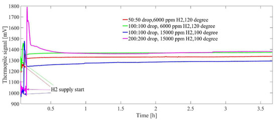
Stability test of the sensor is done with 3 different amount of catalyst at 2 operating temperature for 4 h at 6000 ppm and 15,000 ppm continuous H2 gas flow. The used droplet of Pt nanoparticles and ligand solution in sample I, II and III are 50:50, 100:100, 200:200 consecutively. The droplet has a diameter of around 70 µm, volume of 180 pL and concentration of the solution is 0.123 mol/L. Figure 5 shows sensor response for 4 h continuous operation for different samples. Sensor signals are constant regardless of catalyst amount, H2 concentration and operating temperature that indicate no deactivation of catalyst occurs during experiments.

Figure 5.
Sensor response for different amount of catalyst, different operating temperature and different H2 concentration, Sensor signal remains stable in all cases.
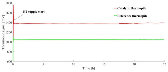
Figure 6 shows that sensor signal is stable and no decrement of output occurs for 24 h continuous operation at 15,000-ppm H2 gas. Therefore, the Catalytic layer is not degraded or deactivated over the time period.

Figure 6.
Sensor response at continuous operation of 24 h, at 15,000-ppm H2 concentration, no degradation of sensor signal is observed, output is completely stable.
4. Discussion
The main disadvantage of thermoresistive gas sensor is that the catalyst exactly over the heater is overheated and on the other places is not sufficiently heated for catalysis. It causes deactivation of catalytic layer and long-term stability of the sensor is hampered. This newly designed thermoelectric sensor provides very good temperature distribution and consumes comparatively low power, the important factor for long-term stable operation of the sensor. The sensor shows excellent stability for 24 h under quite high, 15,000 ppm, H2 gas concentration.
Author Contributions
A.S.P.: sensor design, fabrication and characterization, D.L.: catalytic layer preparation, S.K, M.B., and W.L.: idea and proposal preparation, planning and management of the project.
Acknowledgements
This work is funded by DFG—Deutsche Forschungsgemeinschaft, Project number 299483494.
Conflicts of Interest
The authors declare no conflict of interest.
References
- Brauns, E.; Morsbach, E.; Kunz, S.; Bäumer, M.; Lang, W. A fast and sensitive catalytic gas sensors for hydrogen detection based on stabilized nanoparticles as catalytic layer. Sens. Actuators B Chem. 2014, 193, 895–903. [Google Scholar] [CrossRef]
- Zhou, Q.; Sussman, A.; Chang, J.; Dong, J.; Zettl, A.; Mickelson, W. Fast response integrated MEMS microheaters for ultra-low power gas detection. Sens. Actuators A 2015, 223, 67–75. [Google Scholar] [CrossRef]
- Hwang, W.J.; Shin, K.S.; Roh, J.H.; Lee, D.S.; Choa, S.H. Development of Micro-heaters with optimized temperature compensation design for gas sensors. Sensors 2011, 11, 2580–2591. [Google Scholar] [CrossRef]
- Lee, E.B.; Hwang, I.S.; Cha, J.H.; Lee, H.J.; Lee, W.B.; Pak, J.J.; Lee, J.H.; Ju, B.K. Micromachined catalytic combustible hydrogen gas sensor. Sens. Actuators B 2011, 153, 392–397. [Google Scholar] [CrossRef]
- Harley-Trochimczyk, A.; Chang, J.; Zhou, Q.; Dong, J.; Pham, T.; Worsley, M.A.; Maboudian, R.; Zettl, A.; Mickelson, W. Catalytic hydrogen sensing using micro heated platinum nanoparticle-loaded graphene aerogel. Sens. Actuators B 2015, 206, 399–406. [Google Scholar] [CrossRef]
Publisher’s Note: MDPI stays neutral with regard to jurisdictional claims in published maps and institutional affiliations. |
© 2018 by the authors. Licensee MDPI, Basel, Switzerland. This article is an open access article distributed under the terms and conditions of the Creative Commons Attribution (CC BY) license (https://creativecommons.org/licenses/by/4.0/).