Abstract
Magnetic multimedia control elements have many advantages in comparison with other systems based on mechanical, electrical, or optical readout. For system layouting, the practicality of analytical models over extensive numerical simulation was demonstrated in the past. In this work, we apply the analytical approach to design magnetic multimedia control elements. Particularly, we focus on a joystick that includes only a single 3D magnetic sensor and can be used in continuous operating mode. Presented results relate to a system based on a single permanent magnet and a single 3D sensor. The scheme was used to build a prototype to perform prove of principle experiments. A semi-analytic method to determine positions of the joystick from the observed magnetic field is discussed.
1. Introduction
Multimedia control elements (CE) are widely used in different devices, especially those which are operated without long visual contact (e.g., a navigation system in a car). They can be built on different physical principles: mechanical [1], electrical [2], or optical [3]. Here, magnetic position detection systems have a lot of advantages in comparison with others [4,5]. This is due to wear-free operation, high resolution and low costs of modern magnetic sensors. Today, in the automotive industry there are more than one hundred different applications for magnetic position systems [6]. Their widespread use became possible with new technologies in magnetic detection, particularly, by industrial fabrication of 3D Hall sensors [7].
Development of CE includes solving high dimensional variation problems which require a lot of computation time. For that purpose, fast analytical models are a powerful method. In the case of permanent magnets it is possible to model arbitrary geometry and magnetization [8]. Arbitrary motion given by rotation and translation is easily described mathematically, thus, giving broad possibilities for analytical modeling of magnetic position detection systems. In previous works we presented a magnetic analog of an automotive joystick system such as the iDrive used in BMW cars [9]. It is a discrete system with rotation states and four tilt directions (along ±x- and ±y-axes). To obtain the joystick position, the detected magnetic field is compared with values in a look-up table. This results in a stable operation mode, however, it limits the number of possible positions, as states should be well separated. In addition, searching in a look-up table requires a lot of processing power.
In this work we develop a novel magnetic joystick which features one continuous rotation and one continuous tilt degree of freedom based on a single magnet and a single 3D Hall sensor. The continuous degree of freedom is obtained by a semi-analytical model of the magnetic field. For system design by magnetic shape variation we apply previously developed analytical models.
2. Materials and Methods
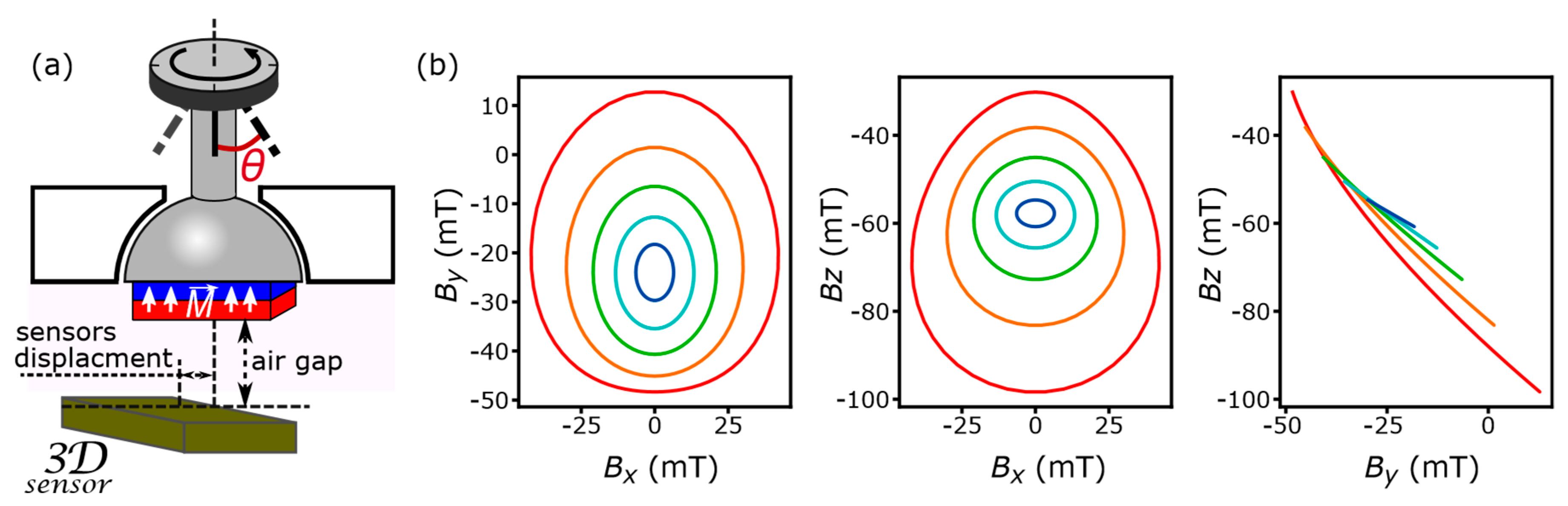
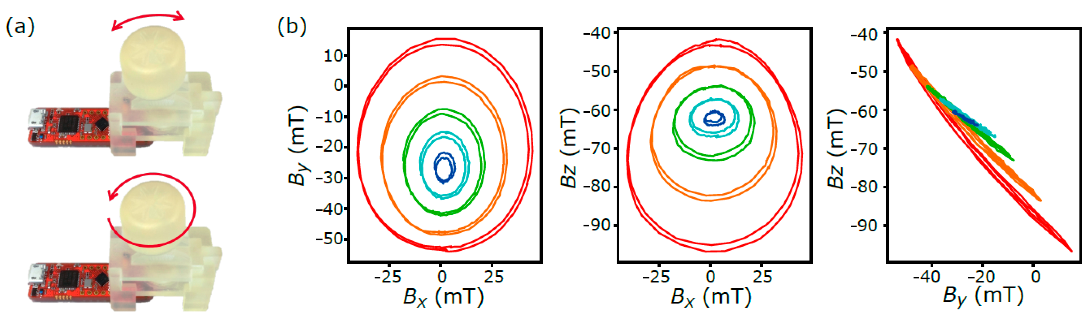
The presented magnetic CE has a rotation movement range of 360-degree. The joystick includes only a single magnet and can be continuously be tilted (angle θ) along the x-axis by ±15 degrees (Figure 1a). A 3D Hall sensor is placed below the permanent magnet and shifted from the rotation axis (z) in x-direction by 1.2 mm (Figure 1a). The magnet has a rectangular shape (8.5 × 2.0 × 1.5 mm) and is magnetized along the z-direction. For the simulations a magnetic remanence field of 990 mT was chosen as a reasonable value for rare earth materials as the analytical model typically overestimates the field. The center of the magnet coincides with the center of tilt and rotation. The small air gap (distance between the bottom surface of the magnet and the sensor sensitive area) results in beneficial large magnetic field amplitudes. However, it also limits the maximal tilt angle. As a compromise, an air gap of 1.2 mm was chosen. Such a geometry provides a unique magnetic map. For the analytical analysis of the magnetic field the method presented in [10] was used together with standard descriptions for motion degrees of freedom.
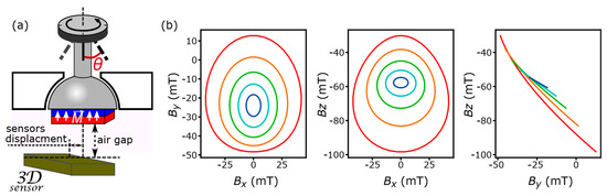
Figure 1.
(a) Schematic illustration of a joystick, which can rotate and tilt along one axis (±x). (b) Different projections of the simulated magnetic field. Green corresponds to the untitled state; red and orange represent tilts with θ equals to 15° and 7.5° respectively; dark and light blue show similar angles of the tilt in the opposite direction.
3. Results
3.1. Simulations of Magnetic Map
To understand the connection between the magnetic sensor output and the joystick position we show the magnetic map for a complete 360° continuous rotation for five tilt positions (tilt angles θ = −15°, −7.5°, 0°, 7.5°, 15°) in Figure 1b. Unfortunately, as a result of the symmetry, already a 180° rotation results in one complete revolution along the ellipsoids in the magnetic output. For rotation movement range of 360° we thus see two curves one on top of another. This is a flaw of the system when a full 360° coverage is required, but for actual CE it is not very critical when one is, for example, navigating through an interface.
3.2. Experimental Results and Data Analysis
In Figure 1b it is possible to notice that each tilt state results in a closed loop of the magnetic field values: Bx-By and Bx-Bz. It looks very much like an oval for one tilt direction (blue lines) and has a deformed egg-like shape for the opposite one (red lines). However, they can be approximated by ellipses with a little error. Their effective radii range from largest, when the joystick is tilted in the direction of sensor shift, to smallest, when it is moved oppositely. One must take care, however, that the centers of the ellipses are located in different positions. This brings some difficulties in sensor output data analysis. Nevertheless, it is possible to apply the analytical method to convert the observed magnetic field into rotation (φ) and tilt (θ) angles with a high degree of accuracy.
An ellipse in x-y space, similar to the one in Figure 1b, can be described by four parameters, x0, y0, Rx and Ry as is shown in the ellipse equation,
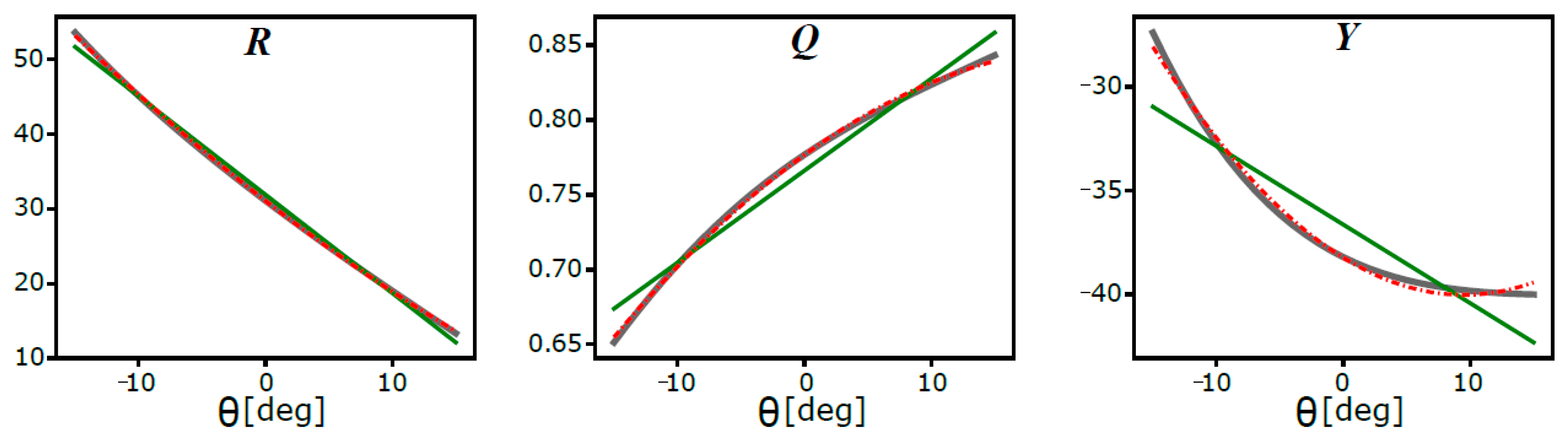
From the magnetic map we immediately realize that x0 = 0 (or constant when an offset is involved) and y0 depends only on the tilt angle, y0 = Y(θ). Also the radii Rx and Ry are only functions of the tilt angle, Rx = R(θ), Ry = Q(θ). The functions R, Q and Y can be determined from the simulation using a least squares approximation and are shown in Figure 2.
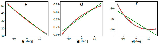
Figure 2.
Parameters R, Q, and Y as functions of tilt angle θ for the case y = By. Grey solid lines—original data; green solid lines—approximation by first order polynomial; red dashed lines—approximation by second order polynomial.
The key to the semi-analytical approach is the approximation of the functions R, Q and Y by second order polynomials from which only the coefficients can be stored in the readout system. The coefficients are found from a calibration of the system and with their help the tilt angle θ can be recovered from the magnetic sensor output. To reduce the error resulting from imperfect ellipses, the analysis can be done simultaneously for different outputs, y:y = By, y = Bz, and/or any convex combination of the two (y = a·By + b·Bz). Finally, the rotation angle can easily be determined for an ellipse with known radius and center position using classical trigonometry.
A prototype based on the proposed design was built at CTR AG. A mechanical structure was developed and 3D printed (Figure 3a). To perform precise measurements, a robot manipulator [11] was used. The robot rotates the joystick for five different tilt angles of −15°, −7.5°, 0°, 7.5° and 15°. The measurement result is presented in Figure 3b. As expected, small splittings between two loops for a tilt state can be observed.

Figure 3.
(a) Photo of a prototype of magnetic joystick. (b) Different projections of observed magnetic field. Green corresponds to the untitled state; red: θ = 15°; orange: 7.5°; light blue: −7.5°; dark: −15°. Black dot lines are oval approximations.
4. Conclusions
We presented a new design of a magnetic multimedia control element, which consists of a single permanent magnet and a single 3D Hall sensor. The proposed system demonstrates a possibility for cost efficient mass production of CE. One big advantage of the presented system is that it has continuous operation and features analytical analysis of readout data, thus requires no powerful micro controller for state detection. The produced prototype demonstrates the feasibility of the proposed model. Our next step would be the development of a magnetic joystick with more degrees of freedom to achieve more flexible system with fast analytical state detection.
Author Contributions
M.O. and D.S. drove the initial idea of development of “one magnet–one sensor” joystick system. A.E. proposed this specific design. A.E. and M.O. provide simulation and analysis method. L.M. performed the experiments and produced final prototype. A.E. wrote that paper.
Funding
This project has been supported by the COMET K1 centre ASSIC Austrian Smart Systems Integration Research Center. The COMET—Competence Centers for Excellent Technologies—Program is supported by BMVIT, BMWFW and the federal provinces of Carinthia and Styria.
Conflicts of Interest
The authors declare no conflict of interest.
References
- Mackway, H.J. Joystick Control Mechanism. U.S. Patent 2929258 A, 22 March 1960. [Google Scholar]
- Bristow, S.D. Joystick with Attached Circuit Elements. U.S. Patent 4091234 A, 23 May 1978. [Google Scholar]
- Goodson, L.E.; Dellinger, C.E. Optical Joystick Controller with Intersecting Spring Means. U.S. Patent 4607159 A, 19 August 1986. [Google Scholar]
- Marshall, S.; Alexander, A.; Ashraf, M.M. Joystick Controller Using Magnetic Position Sensors and a Resilien Control Arm with Sensor Used to Measure Its Flex. U.S. Patent 5831596 A, 3 November 1998. [Google Scholar]
- Schottler, J.J. Magnetic Ball Joystick. U.S. Patent 5969520 A, 19 October 1999. [Google Scholar]
- Infineon Technologies AG, Sensing the World. 2017. Available online: www.infineon.at (accessed on 1 May 2017).
- Kejik, P.; Schurig, E.; Bergsma, F.; Popovic, R.S. First fully CMOS-integrated 3D Hall probe. In Proceedings of the The 13th International Conference on Solid-state Sensors, Actuators and Microsystems, Seoul, Korea, 5–9 June 2005; pp. 317–320. [Google Scholar] [CrossRef]
- Rubeck, C.; Yonnet, J.P.; Allag, H.; Delinchant, B.; Chadebec, O. Analytical Calculation of Magnet Systems: 109 Magnetic Field Created by Charged Triangles and Polyhedra. IEEE Trans. Magn. 2013, 49, 144–147. [Google Scholar] [CrossRef]
- Ermakova, A.; Ribeiro, M.; Spitzer, D.; Ortner, M. Analytical Development of a 4-Axis Magnetic Multimedia Control Element. IEEE Sens. J. 2018. [Google Scholar] [CrossRef]
- Yang, Z.J.; Johansen, T.H.; Bratsberg, H.; Helgesen, G.; Skjeltorp, A.T. Potential and force between a magnet and a bulk Y1Ba2Cu3O7−δ superconductor studied by a mechanical pendulum. Supercond. Sci. Technol. 1990, 3. [Google Scholar] [CrossRef]
- Ribeiro, M. Robot-Aided Magnetic Sensors Readout Suit. In Proceedings of the 9th International Conference on Sensing Technology (ICST), Auckland, New Zealand, 8–10 December 2015; pp. 706–710. [Google Scholar] [CrossRef]
Publisher’s Note: MDPI stays neutral with regard to jurisdictional claims in published maps and institutional affiliations. |
© 2018 by the authors. Licensee MDPI, Basel, Switzerland. This article is an open access article distributed under the terms and conditions of the Creative Commons Attribution (CC BY) license (https://creativecommons.org/licenses/by/4.0/).